LEXUS SC400 1991 Service Repair Manual
Manufacturer: LEXUS, Model Year: 1991,
Model line: SC400,
Model: LEXUS SC400 1991
Pages: 4087, PDF Size: 75.75 MB
LEXUS SC400 1991 Service Repair Manual
SC400 1991
LEXUS
LEXUS
https://www.carmanualsonline.info/img/36/57051/w960_57051-0.png
LEXUS SC400 1991 Service Repair Manual
Trending: coolant capacity, fuel tank removal, oxygen sensor, evap, CD player, open hood, exhaust
Page 2321 of 4087
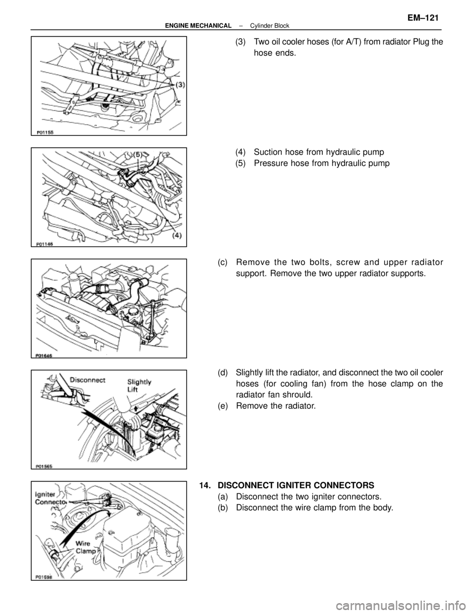
(3) Two oil cooler hoses (for A/T) from radiator Plug thehose ends.
(4) Suction hose from hydraulic pump
(5) Pressure hose from hydraulic pump
(c) Re mo ve th e two bo lts, scre w an d u pper radiator
support. Remove the two upper radiator supports.
(d) Slightly lift the radiator, and d isconnect the two oil cooler
hoses (for cooling fan) from the hose clamp on the
radiator fan shrould.
(e) Remove the radiator.
14. DISCONNECT IGNITER CONNECTORS (a) Disconnect the two igniter connectors.
(b) Disconnect the wire clamp from the body.
±
ENGINE MECHANICAL Cylinder BlockEM±121
WhereEverybodyKnowsYourName
Page 2322 of 4087
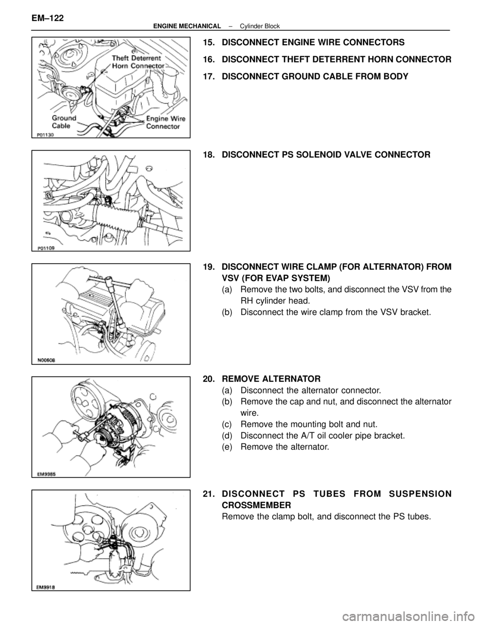
15. DISCONNECT ENGINE WIRE CONNECTORS
16. DISCONNECT THEFT DETERRENT HORN CONNECTOR
17. DISCONNECT GROUND CABLE FROM BODY
18. DISCONNECT PS SOLENOID VALVE CONNECTOR
19. DISCONNECT WIRE CLAMP (FOR ALTERNATOR) FROMVSV (FOR EVAP SYSTEM)
(a) Remove the two bolts, and disconnect the VSV from the
RH cylinder head.
(b) Disconnect the wire clamp from the VSV bracket.
20. REMOVE ALTERNATOR (a) Disconnect the alternator connector.
(b) Remove the cap and nut, and disconnect the alternatorwire.
(c) Remove the mounting bolt and nut.
(d) Disconnect the A/T oil cooler pipe bracket.
(e) Remove the alternator.
21. D I S C O N N E C T P S T U B E S F R O M S U SPENSION
CROSSMEMBER
Remove the clamp bolt, and disconnect the PS tubes.
EM±122
±
ENGINE MECHANICAL Cylinder Block
WhereEverybodyKnowsYourName
Page 2323 of 4087
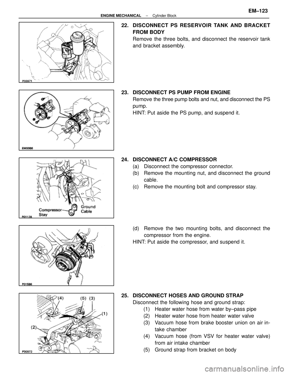
22. DISCONNECT PS RESERVOIR TANK AND BRACKET
FROM BODY
Remove the three bolts, and disconnect the reservoir tank
and bracket assembly.
23. DISCONNECT PS PUMP FROM ENGINE Remove the three pump bolts and nut, and disconnect the PS
pump.
HINT: Put aside the PS pump, and suspend it.
24. DISCONNECT A/C COMPRESSOR (a) Disconnect the compressor connector.
(b) Remove the mounting nut, and disconnect the groundcable.
(c) Remove the mounting bolt and compressor stay.
(d) Remove the two mounting bolts, and disconnect the compressor from the engine.
HINT: Put aside the compressor, and suspend it.
25. DISCONNECT HOSES AND GROUND STRAP Disconnect the following hose and ground strap:(1) Heater water hose from water by±pass pipe
(2) Heater water hose from heater water valve
(3) Vacuum hose from brake booster union on air in-
take chamber
(4) Vacuum hose (from VSV for heater water valve)
from air intake chamber
(5) Ground strap from bracket on body
±
ENGINE MECHANICAL Cylinder BlockEM±123
WhereEverybodyKnowsYourName
Page 2324 of 4087
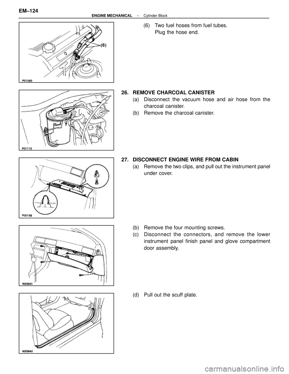
(6) Two fuel hoses from fuel tubes. Plug the hose end.
26. REMOVE CHARCOAL CANISTER (a) Disconnect the vacuum hose and air hose from thecharcoal canister.
(b) Remove the charcoal canister.
27. DISCONNECT ENGINE WIRE FROM CABIN (a) Remove the two clips, and pull out the instrument panelunder cover.
(b) Remove the four mounting screws.
(c) Disc onnect the connectors, and remove the lower
instrument panel finish panel and glove compartment
door assembly.
(d) Pull out the scuff plate.
EM±124
±
ENGINE MECHANICAL Cylinder Block
WhereEverybodyKnowsYourName
Page 2325 of 4087
(e) Take out the front side of the floor carpet.
(f) Remove the two nuts and ECU protector.
(g) Remove the nut, and disconnect the engine & ECT ECU
from the floor panel.
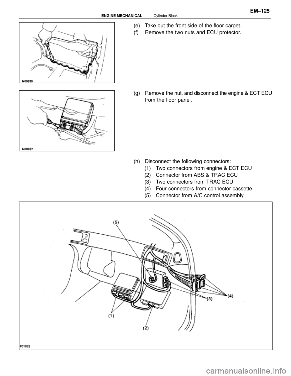
(h) Disconnect the following connectors: (1) Two connectors from engine & ECT ECU
(2) Connector from ABS & TRAC ECU
(3) Two connectors from TRAC ECU
(4) Four connectors from connector cassette
(5) Connector from A/C control assembly
±
ENGINE MECHANICAL Cylinder BlockEM±125
WhereEverybodyKnowsYourName
Page 2326 of 4087
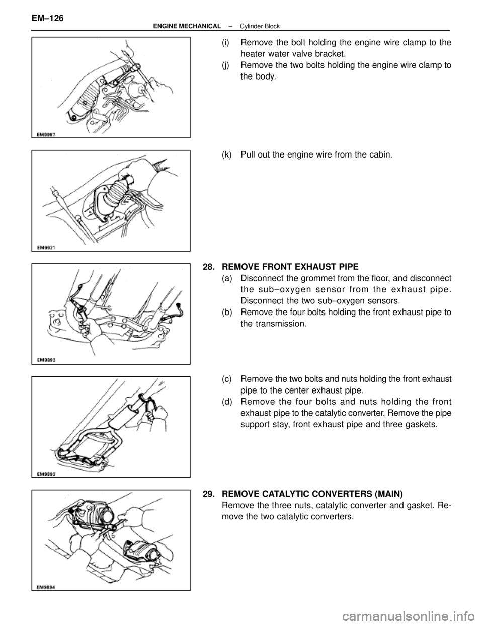
(i) Remove the bolt holding the engine wire clamp to theheater water valve bracket.
(j) Remove the two bolts holding the engine wire clamp to the body.
(k) Pull out the engine wire from the cabin.
28. REMOVE FRONT EXHAUST PIPE (a) Disconnect the grommet from the floor, and disconnectthe sub±oxygen sensor from the exhaust pipe.
Disconnect the two sub±oxygen sensors.
(b) Remove the four bolts holding the front exhaust pipe to the transmission.
(c) Remove the two bolts and nuts holding the front exhaust
pipe to the center exhaust pipe.
(d) Re mo ve th e fo u r bo lts an d nu ts ho ld in g th e fro n t
exhaust pipe to the catalytic converter. Remove the pipe
support stay, front exhaust pipe and three gaskets.
29. REMOVE CATALYTIC CONVERTERS (MAIN) Remove the three nuts, catalytic converter and gasket. Re-
move the two catalytic converters.
EM±126
±
ENGINE MECHANICAL Cylinder Block
WhereEverybodyKnowsYourName
Page 2327 of 4087
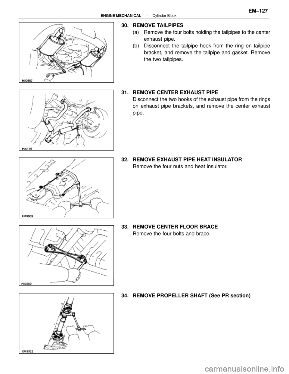
30. REMOVE TAILPIPES(a) Remove the four bolts holding the tailpipes to the centerexhaust pipe.
(b) Disconnect the tailpipe hook from the ring on tailpipe
bracket, and remove the tailpipe and gasket. Remove
the two tailpipes.
31. REMOVE CENTER EXHAUST PIPE Disconnect the two hooks of the exhaust pipe from the rings
on exhaust pipe brackets, and remove the center exhaust
pipe.
32. REMOVE EXHAUST PIPE HEAT INSULATOR Remove the four nuts and heat insulator.
33. REMOVE CENTER FLOOR BRACE Remove the four bolts and brace.
34. REMOVE PROPELLER SHAFT (See PR section)
±
ENGINE MECHANICAL Cylinder BlockEM±127
WhereEverybodyKnowsYourName
Page 2328 of 4087
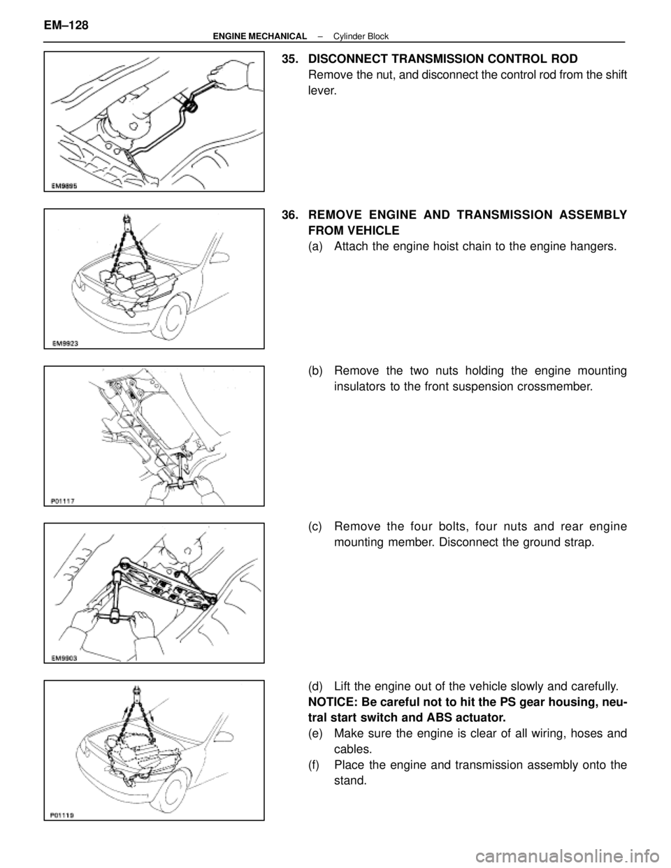
35. DISCONNECT TRANSMISSION CONTROL RODRemove the nut, and disconnect the control rod from the shift
lever.
36. REMOVE ENGINE AND TRANSMISSION A SSEMBLY
FROM VEHICLE
(a) Attach the engine hoist chain to the engine hangers.
(b) Remove the two nuts holding the engine mounting insulators to the front suspension crossmember.
(c) Remove the four bolts, four nuts and rear engine mounting member. Disconnect the ground strap.
(d) Lift the engine out of the vehicle slowly and carefully.
NOTICE: Be careful not to hit the PS gear housing, neu-
tral start switch and ABS actuator.
(e) Make sure the engine is clear of all wiring, hoses and cables.
(f) Place the engine and transmission assembly onto the stand.
EM±128
±
ENGINE MECHANICAL Cylinder Block
WhereEverybodyKnowsYourName
Page 2329 of 4087
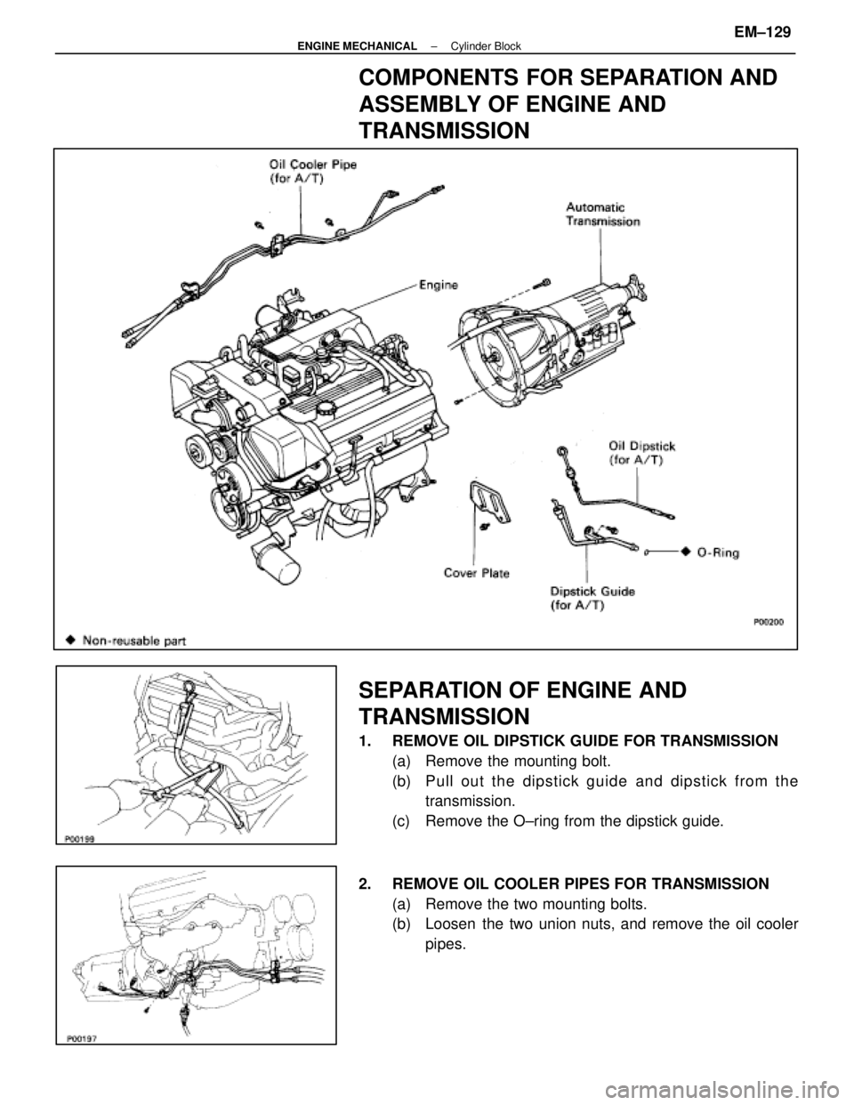
COMPONENTS FOR SEPARATION AND
ASSEMBLY OF ENGINE AND
TRANSMISSION
SEPARATION OF ENGINE AND
TRANSMISSION
1. REMOVE OIL DIPSTICK GUIDE FOR TRANSMISSION(a) Remove the mounting bolt.
(b) P u ll ou t th e dip stick gu id e an d dip stick fro m th etransmission.
(c) Remove the O±ring from the dipstick guide.
2. REMOVE OIL COOLER PIPES FOR TRANSMISSION (a) Remove the two mounting bolts.
(b) Loosen the two union nuts, and remove the oil coolerpipes.
±
ENGINE MECHANICAL Cylinder BlockEM±129
WhereEverybodyKnowsYourName
Page 2330 of 4087
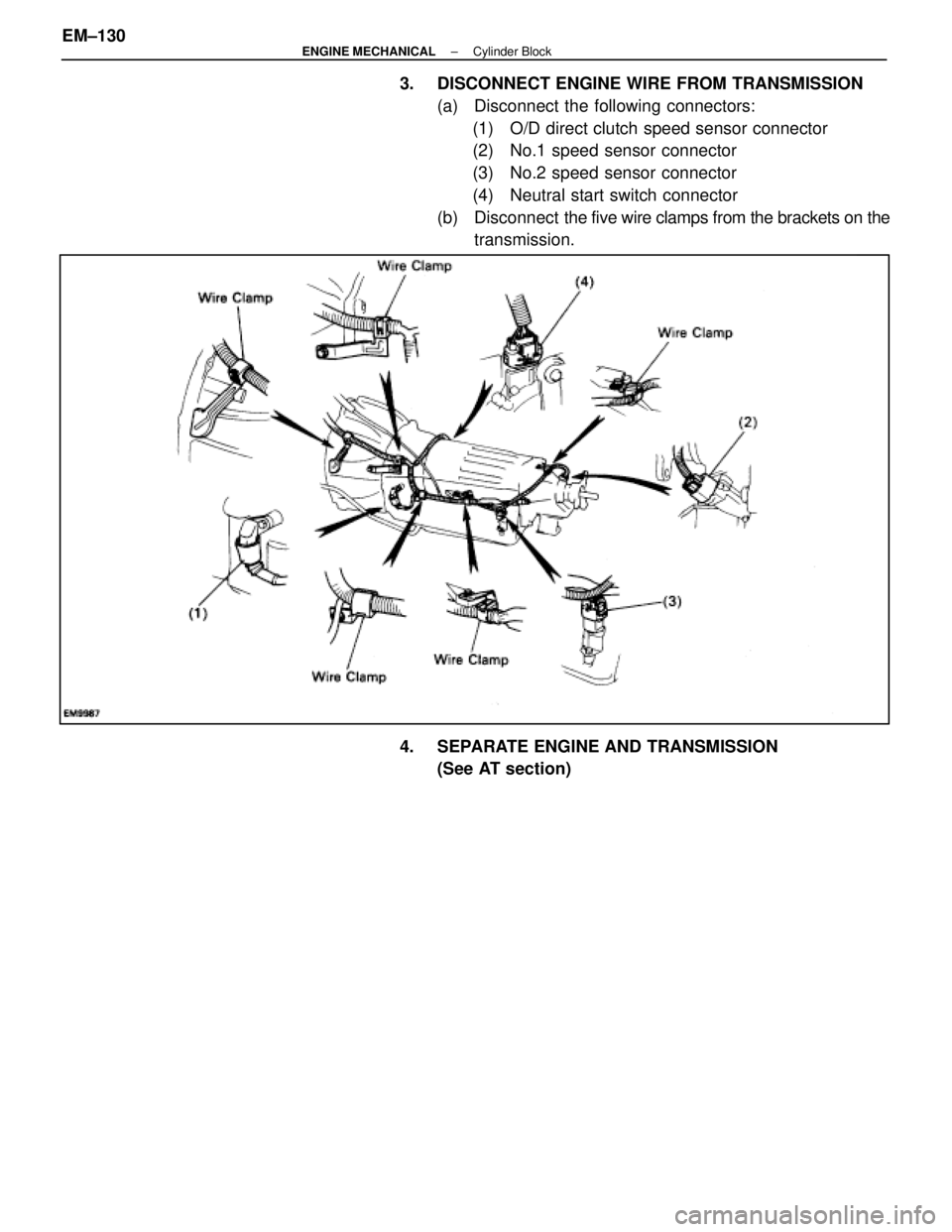
3. DISCONNECT ENGINE WIRE FROM TRANSMISSION(a) Disconnect the following connectors:(1) O/D direct clutch speed sensor connector
(2) No.1 speed sensor connector
(3) No.2 speed sensor connector
(4) Neutral start switch connector
(b) Disconnect the five wire clamps from the brackets on the
transmission.
4. SEPARATE ENGINE AND TRANSMISSION (See AT section)
EM±130
±
ENGINE MECHANICAL Cylinder Block
WhereEverybodyKnowsYourName
Trending: oil type, brake pads, fuel cap, coolant capacity, suspension, air filter, oil dipstick
