Strut LEXUS SC400 1991 Service Repair Manual
[x] Cancel search | Manufacturer: LEXUS, Model Year: 1991, Model line: SC400, Model: LEXUS SC400 1991Pages: 4087, PDF Size: 75.75 MB
Page 492 of 4087

Suspension Crossmember Drawings (Cont'd)
(Three±Dimensional Distance)
(Two±Dimensional Distance)
SymbleNameHole dia.SymbleNameHole dia.
A,aStrut bar installation hole inner14 (0.55)F, fLower arm installation hole front26 x 14
(1.02 x 0.55)
B,bDifferential carrier installation hole12 (0.47) screwG,gRear suspension member standard hole20 (0.78)
C,cRear suspension member standard hole20 (0.78)H,hLower arm installation hole rear26 x 14
(1.02 x 0.55)
D,dLower arm installation hole front26 x 14
(1.02 x 0.55)I,iUpper arm installation hole rear14 (0.55)
E,eUpper arm installation hole front14 (0.55)'''
±
BODY Body Dimensions (Suspension Crossmember Drawings)BO±137
WhereEverybodyKnowsYourName
Page 980 of 4087

PARKING BRAKE
BR03H±04
When the parking brake lever is pulled up, the parking brake shoe lever is p\
ulled via the parking brake wire.
This causes the shoe strut to push the front shoe, which expands and is pres\
sed against the disc. If the
parking brake lever continues to be pulled up, the contact point of the parking\
brake shoe lever and shoe
strut then becomes the fulcrum so that the parking brake shoe lever causes th\
e rear shoe to expand. This
results in the disc being locked by the front shoe and rear shoe.
±
BRAKE SYSTEM OPERATIONBR±3
WhereEverybodyKnowsYourName
Page 1014 of 4087

4. REMOVE SHOE RETURN SPRINGSUsing needle±nose pliers, remove the 2 shoe return springs.
5. REMOVE SHOE STRUT WITH SPRING
6. REMOVE FRONT SHOE ADJUSTER AND TENSION SPRING
(a) Slide out the front shoe and remove the shoe adjuster.
(b) Disconnect the tension spring and remove the front shoe.
7. REMOVE REAR SHOE
(a) Slide out the rear shoe.
(b) Remove the tension spring from the rear shoe.
(c) Disconnect the parking brake cable from the parking brake
shoe lever.
(d) Remove the shoe hold±down spring cups, springs and pins.
±
BRAKE SYSTEM REAR BRAKE (Parking Brake)BR±45
WhereEverybodyKnowsYourName
Page 1018 of 4087
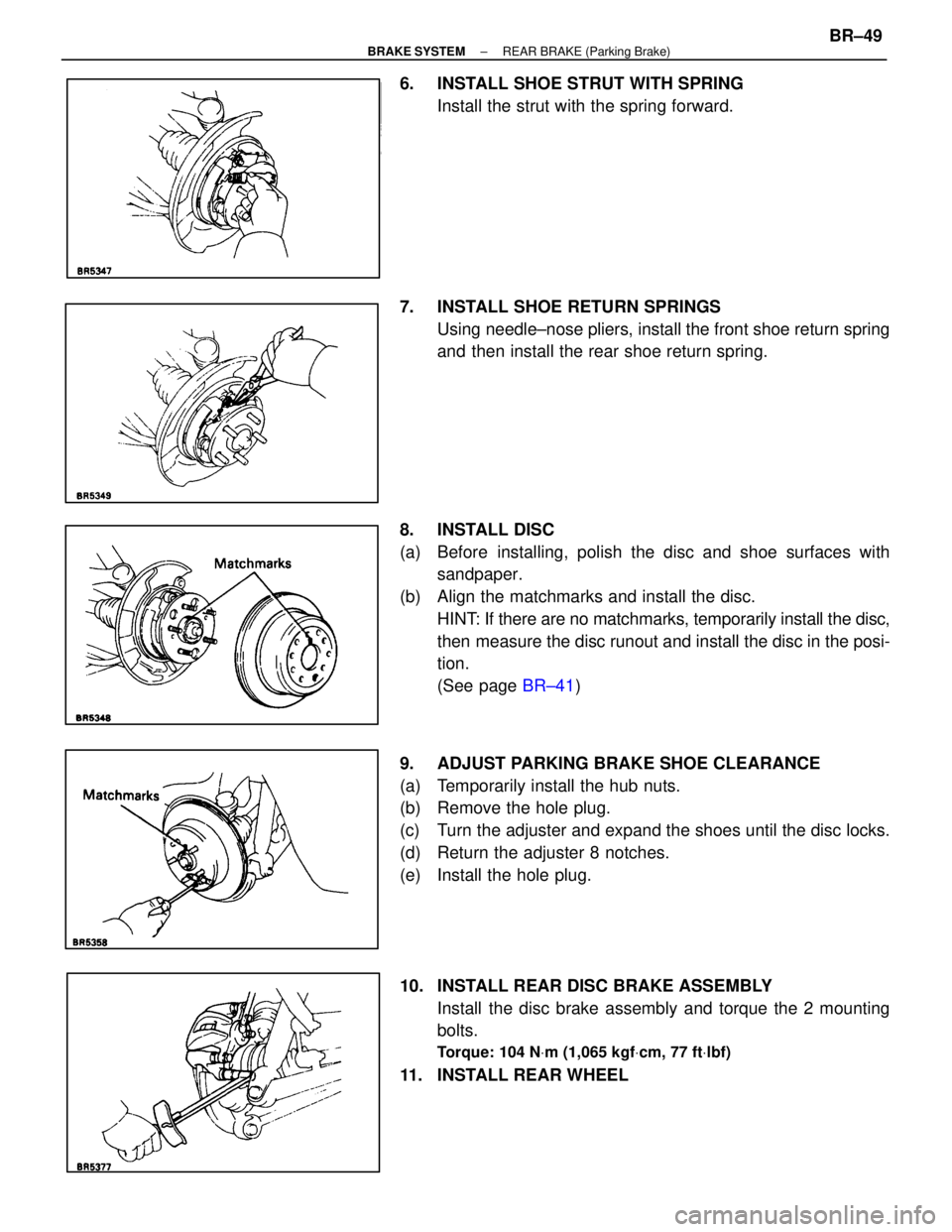
6. INSTALL SHOE STRUT WITH SPRINGInstall the strut with the spring forward.
7. INSTALL SHOE RETURN SPRINGS Using needle±nose pliers, install the front shoe return spring
and then install the rear shoe return spring.
8. INSTALL DISC
(a) Before installing, polish the disc and shoe surfaces with sandpaper.
(b) Align the matchmarks and install the disc. HINT: If there are no matchmarks, temporarily install the disc,
then measure the disc runout and install the disc in the posi-
tion.
(See page BR±41)
9. ADJUST PARKING BRAKE SHOE CLEARANCE
(a) Temporarily install the hub nuts.
(b) Remove the hole plug.
(c) Turn the adjuster and expand the shoes until the disc locks.
(d) Return the adjuster 8 notches.
(e) Install the hole plug.
10. INSTALL REAR DISC BRAKE ASSEMBLY Install the disc brake assembly and torque the 2 mounting
bolts.
Torque: 104 N Vm (1,065 kgf Vcm, 77 ft Vlbf)
11. INSTALL REAR WHEEL
±
BRAKE SYSTEM REAR BRAKE (Parking Brake)BR±49
WhereEverybodyKnowsYourName
Page 1241 of 4087

mm (in.)
BO6852
BO6852
(Two-Dimensional Distance) (Three-Dimensional Distance)
SymbolName Hole dia.
Symbol Name Hole dia.
A, a Strut bar installation hole inner
14 (0.55)F, fLower arm installation hole front 26
y14
(1.02 y0.55)
B, b Differential carrier installation nut 12 (0.47) nut G, gRear suspension member standard
hole
20 (0.78)
C, c Rear suspension member standard
hole 20 (0.78)
H, hLower arm installation hole rear 26
y14
(1.02 y0.55)
D, d Lower arm installation hole front 26
yl4
1.02 y0.55 I, i
Upper arm installation hole rear 14 (0.55)
E, e Upper arm installation hole front 14 (0.55)
Suspension Crossmember (Cont'd)
BODY DIMENSIONSDI-12
WhereEverybodyKnowsYourName
Page 3250 of 4087

LOWER SUSPENSION ARM AND
STRUT ROD
COMPONENTS
SA0SL±03
±
SUSPENSION AND AXLE REAR SUSPENSIONSA±117
WhereEverybodyKnowsYourName
Page 3251 of 4087

LOWER SUSPENSION ARMS AND
STRUT ROD REMOVAL
SA1A8±01
1. JACK UP VEHICLE AND REMOVE REAR WHEEL
2. REMOVE BRAKE CALIPER AND DISC
(a) Remove the 2 bolts and brake caliper from the axle hub.
(b) Hang up the brake caliper using wire, etc.
3. REMOVE STRUT ROD
(a) Remove the bolt and nut, disconnect the strut rod from therear axle carrier.
(b) Remove the bolt and nut and the strut rod.
4. REMOVE NO.1 LOWER SUSPENSION ARM
(a) Remove the nut.
(b) Using SST, disconnect the lower suspension arm from the axle carrier.
SST 09628±10011
NOTICE: Be careful not to damage the dust boot.
SA±118±
SUSPENSION AND AXLE REAR SUSPENSION
WhereEverybodyKnowsYourName
Page 3253 of 4087

STRUT ROD BUSHING REPLACEMENT
SA0WC±01
REPLACE STRUT ROD BUSHING
Using SST, replace the strut rod bushing.
SST 09710±30020 (09710±03110, 09710±03120)
LOWER SUSPENSION ARM NO.1 AND
NO. 2 BALL JOINT INSPECTION
SA0UP±02
INSPECT BALL JOINT FOR ROTATION CONDITION
(a) Flip the ball joint stud back and forth 5 times, before installing the nut.
(b) Using a torque wrench, turn the nut continuously one turn every 2±4 seconds and take the torque reading on the 5th
turn.
Torque:
Lower suspension arm No.1
1.0 ± 3.4 N Vm (10 ± 35 kgf Vcm, 9 ± 30 in. Vlbf)
Lower suspension arm No.2 1.0 ± 3.4 N Vm (10 ± 35 kgf Vcm, 9 ± 30 in. Vlbf)
If not within specification, replace the lower suspension arm
No.1 or/and No.2.
LOWER SUSPENSION ARMS AND
STRUT ROD INSTALLATION
SA1A9±01
1. INSTALL NO.2 LOWER SUSPENSION ARM
(a) Install the l ower suspension arm to the carrier with a new nut.
Torque: 150 NVm (1,525 kgf Vcm, 110 ft Vlbf)
(b) Connect the lower suspension arm to the body.
(c) Temporarily install the adjusting cam and nut.
(d) Align matchmarks on the adjusting cam and body.
SA±120
±
SUSPENSION AND AXLE REAR SUSPENSION
WhereEverybodyKnowsYourName
Page 3254 of 4087

(e) Temporarily connect the shock absorber to the lower arm with
the bolt and nut.
(f) Connect the stabilizer bar link to the lower suspension arm with the nut.
Torque: 74 N Vm (750 kgf Vcm, 54 ft Vlbf)
2. INSTALL NO.1 LOWER SUSPENSION ARM
(a) Install the lower suspension arm to the axle carrier with a new
nut.
Torque: 59 N Vm (600 kgf Vcm, 43 ft Vlbf)
(b) Connect the lower suspension arm to the body.
(c) Temporarily install the adjusting cam and nut.
(d) Align the matchmarks on the adjusting cam and body.
3. INSTALL STRUT ROD
(a) Temporarily install the strut rod to the body with the bolt and
nut.
±
SUSPENSION AND AXLE REAR SUSPENSIONSA±121
WhereEverybodyKnowsYourName
Page 3255 of 4087

(b) Temporarily connect the strut rod to the axle carrier with thebolt and nut.
4. INSTALL BRAKE CALIPER Install the brake caliper with the 2 bolts.
Torque: 104 N Vm (1,065 kgf Vcm, 77 ft Vlbf)
5. STABILIZE SUSPENSION
(a) Install the rear wheel and lower vehicle.
(b) Bounce the vehicle up and down several times to stabilize the
suspension.
(c) Jack up the vehicle and remove rear wheel.
6. TORQUE BOLTS AND NUTS
(a) Support the rear axle carrier with a jack.
(b) Torque the bolts and nuts of the strut rod.
Torque: 184 N Vm (1,880 kgf Vcm, 136 ft Vlbf)
(c) Torque the nut.
Torque: 143 N Vm (1,460 kgf Vcm, 106 ft Vlbf)
SA±122±
SUSPENSION AND AXLE REAR SUSPENSION
WhereEverybodyKnowsYourName