headlamp LINCOLN AVIATOR 2003 User Guide
[x] Cancel search | Manufacturer: LINCOLN, Model Year: 2003, Model line: AVIATOR, Model: LINCOLN AVIATOR 2003Pages: 288, PDF Size: 3.32 MB
Page 59 of 288
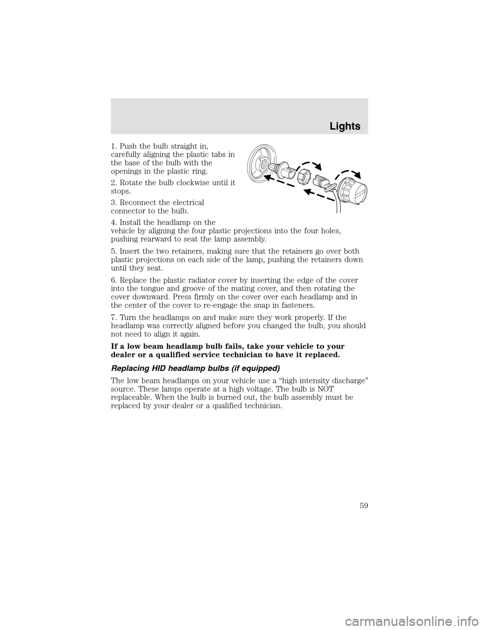
1. Push the bulb straight in,
carefully aligning the plastic tabs in
the base of the bulb with the
openings in the plastic ring.
2. Rotate the bulb clockwise until it
stops.
3. Reconnect the electrical
connector to the bulb.
4. Install the headlampon the
vehicle by aligning the four plastic projections into the four holes,
pushing rearward to seat the lamp assembly.
5. Insert the two retainers, making sure that the retainers go over both
plastic projections on each side of the lamp, pushing the retainers down
until they seat.
6. Replace the plastic radiator cover by inserting the edge of the cover
into the tongue and groove of the mating cover, and then rotating the
cover downward. Press firmly on the cover over each headlampand in
the center of the cover to re-engage the snapin fasteners.
7. Turn the headlamps on and make sure they work properly. If the
headlampwas correctly aligned before you changed the bulb, you should
not need to align it again.
If a low beam headlamp bulb fails, take your vehicle to your
dealer or a qualified service technician to have it replaced.
Replacing HID headlamp bulbs (if equipped)
The low beam headlamps on your vehicle use a “high intensity discharge”
source. These lamps operate at a high voltage. The bulb is NOT
replaceable. When the bulb is burned out, the bulb assembly must be
replaced by your dealer or a qualified technician.
Lights
59
Page 60 of 288
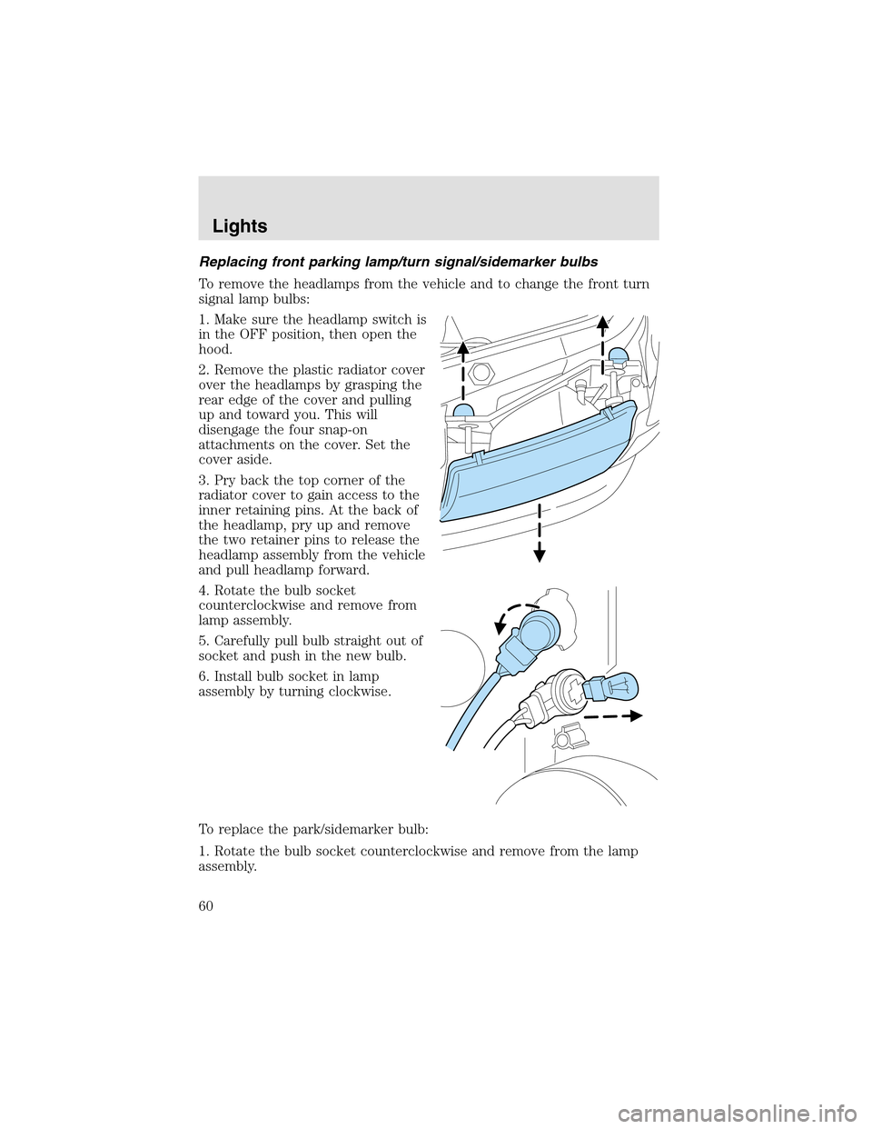
Replacing front parking lamp/turn signal/sidemarker bulbs
To remove the headlamps from the vehicle and to change the front turn
signal lampbulbs:
1. Make sure the headlampswitch is
in the OFF position, then open the
hood.
2. Remove the plastic radiator cover
over the headlamps by grasping the
rear edge of the cover and pulling
upand toward you. This will
disengage the four snap-on
attachments on the cover. Set the
cover aside.
3. Pry back the topcorner of the
radiator cover to gain access to the
inner retaining pins. At the back of
the headlamp, pry up and remove
the two retainer pins to release the
headlampassembly from the vehicle
and pull headlamp forward.
4. Rotate the bulb socket
counterclockwise and remove from
lampassembly.
5. Carefully pull bulb straight out of
socket and push in the new bulb.
6. Install bulb socket in lamp
assembly by turning clockwise.
To replace the park/sidemarker bulb:
1. Rotate the bulb socket counterclockwise and remove from the lamp
assembly.
Lights
60
Page 61 of 288
2. Carefully pull the bulb straight out of the socket and push in the new
bulb.
3. Install the bulb socket in the lampassembly by turning it
counterclockwise.
To re-install the headlampon the vehicle:
1. Install the headlampon the vehicle by aligning the four plastic
projections into the four holes, pushing rearward to seat the lamp
assembly.
2. Insert the two retainers, making sure that the retainers go over both
plastic projections on each side of the lamp, pushing the retainers down
until they seat.
3. Replace the plastic radiator cover by inserting the edge of the cover
into the tongue and groove of the mating cover, and then rotating the
cover downward. Press firmly on the cover over each headlampand in
the center of the cover to re-engage the snap-in fasteners.
4. Turn the headlamps on and make sure they work properly.
Replacing tail/brake/turn/sidemarker/backup lamp bulbs
The tail/brake/turn/sidemarker/backupbulbs are located in the tail lamp
assembly, one just below the other. Follow the same steps to replace
each bulb:
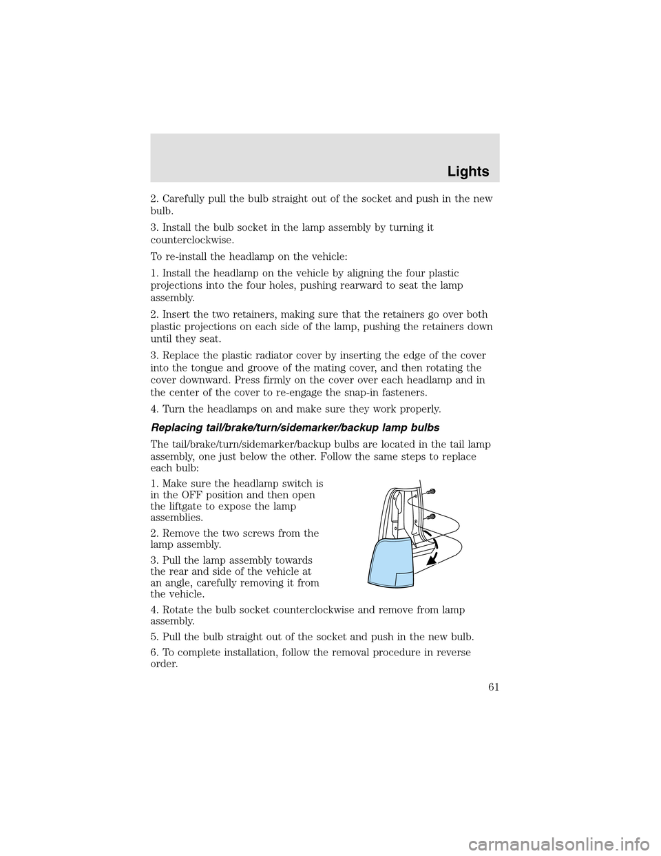
1. Make sure the headlampswitch is
in the OFF position and then open
the liftgate to expose the lamp
assemblies.
2. Remove the two screws from the
lampassembly.
3. Pull the lampassembly towards
the rear and side of the vehicle at
an angle, carefully removing it from
the vehicle.
4. Rotate the bulb socket counterclockwise and remove from lamp
assembly.
5. Pull the bulb straight out of the socket and push in the new bulb.
6. To complete installation, follow the removal procedure in reverse
order.
Lights
61
Page 62 of 288
Replacing liftgate tail lamp bulb
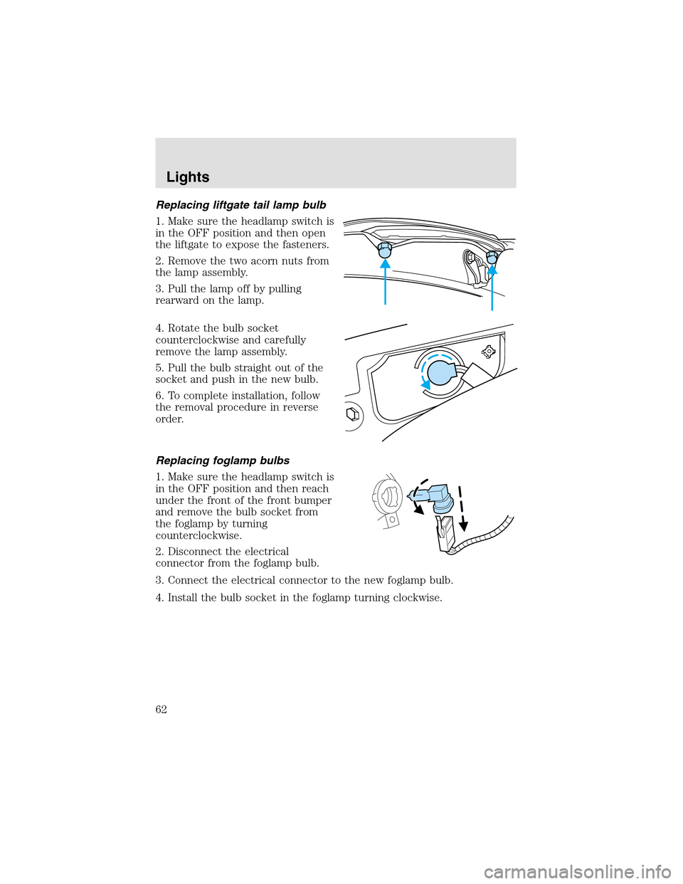
1. Make sure the headlampswitch is
in the OFF position and then open
the liftgate to expose the fasteners.
2. Remove the two acorn nuts from
the lampassembly.
3. Pull the lampoff by pulling
rearward on the lamp.
4. Rotate the bulb socket
counterclockwise and carefully
remove the lampassembly.
5. Pull the bulb straight out of the
socket and push in the new bulb.
6. To complete installation, follow
the removal procedure in reverse
order.
Replacing foglamp bulbs
1. Make sure the headlampswitch is
in the OFF position and then reach
under the front of the front bumper
and remove the bulb socket from
the foglampby turning
counterclockwise.
2. Disconnect the electrical
connector from the foglampbulb.
3. Connect the electrical connector to the new foglampbulb.
4. Install the bulb socket in the foglampturning clockwise.
Lights
62
Page 63 of 288
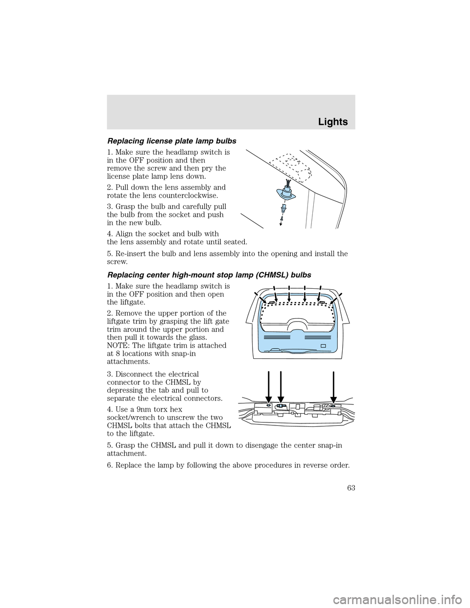
Replacing license plate lamp bulbs
1. Make sure the headlampswitch is
in the OFF position and then
remove the screw and then pry the
license plate lamp lens down.
2. Pull down the lens assembly and
rotate the lens counterclockwise.
3. Graspthe bulb and carefully pull
the bulb from the socket and push
in the new bulb.
4. Align the socket and bulb with
the lens assembly and rotate until seated.
5. Re-insert the bulb and lens assembly into the opening and install the
screw.
Replacing center high-mount stop lamp (CHMSL) bulbs
1. Make sure the headlampswitch is
in the OFF position and then open
the liftgate.
2. Remove the upper portion of the
liftgate trim by grasping the lift gate
trim around the upper portion and
then pull it towards the glass.
NOTE: The liftgate trim is attached
at 8 locations with snap-in
attachments.
3. Disconnect the electrical
connector to the CHMSL by
depressing the tab and pull to
separate the electrical connectors.
4. Use a 9nm torx hex
socket/wrench to unscrew the two
CHMSL bolts that attach the CHMSL
to the liftgate.
5. Grasp the CHMSL and pull it down to disengage the center snap-in
attachment.
6. Replace the lamp by following the above procedures in reverse order.
Lights
63
Page 64 of 288
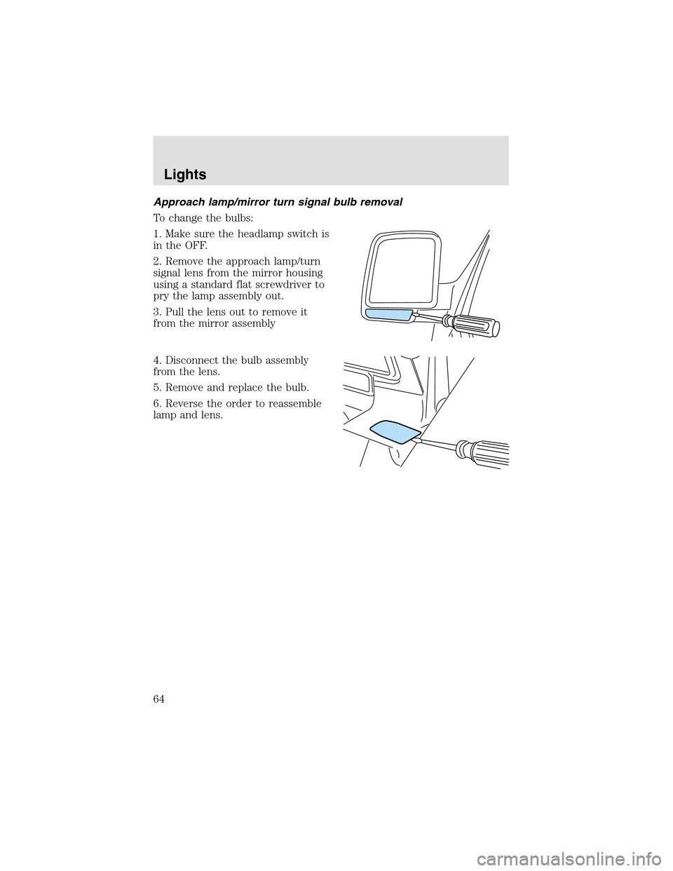
Approach lamp/mirror turn signal bulb removal
To change the bulbs:
1. Make sure the headlampswitch is
in the OFF.
2. Remove the approach lamp/turn
signal lens from the mirror housing
using a standard flat screwdriver to
pry the lamp assembly out.
3. Pull the lens out to remove it
from the mirror assembly
4. Disconnect the bulb assembly
from the lens.
5. Remove and replace the bulb.
6. Reverse the order to reassemble
lampand lens.
Lights
64
Page 117 of 288
6. To program additional new unprogrammed key(s), repeat this
procedure from step 1.
If successful, the new coded key(s) will start the vehicle’s engine and the
theft indicator will illuminate for three seconds and then go out.
If not successful, the new coded key(s) will not start the vehicle’s engine
and the theft indicator will flash on and off and you may repeat steps 1
through 5. If failure repeats, bring your vehicle to your dealership to
have the new spare key(s) programmed.
PERIMETER ALARM SYSTEM
The perimeter anti-theft system will help prevent your vehicle from
unauthorized entry.
If there is any potential perimeter anti-theft problem with your vehicle,
ensureALL remote entry transmittersare brought to the dealership,
to aid in troubleshooting.
Arming the system
When armed, this system will helpprotect your vehicle from
unauthorized entry. When unauthorized entry occurs, the system will
flash the headlamps and/or parking lamps, and will chirp the horn.
The system is ready to arm whenever the key is removed from the
ignition. Any of the following actions will prearm the alarm system:
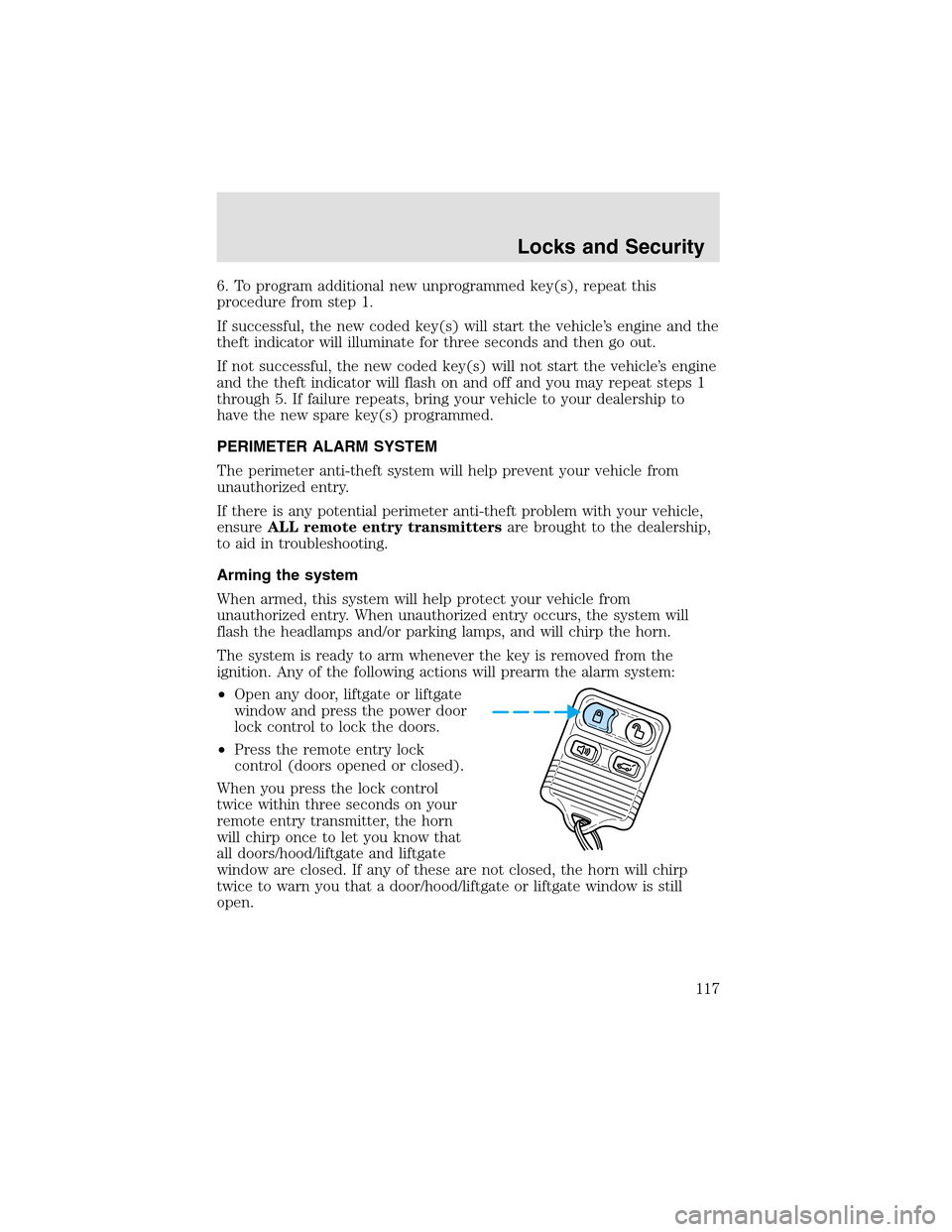
•Open any door, liftgate or liftgate
window and press the power door
lock control to lock the doors.
•Press the remote entry lock
control (doors opened or closed).
When you press the lock control
twice within three seconds on your
remote entry transmitter, the horn
will chirponce to let you know that
all doors/hood/liftgate and liftgate
window are closed. If any of these are not closed, the horn will chirp
twice to warn you that a door/hood/liftgate or liftgate window is still
open.
Locks and Security
117
Page 141 of 288
Reasons given... Consider...
“I have an air bag” Air bags offer greater protection when
used with safety belts. Frontal airbags
are not designed to inflate in rear and
side crashes or rollovers.
“I’d rather be thrown clear” Not a good idea.Peoplewho are
ejected are 40 times more likely
to DIE.Safety belts helpprevent
ejection, WE CAN’T “PICK OUR
CRASH”.
Do not sit on topof a buckled safety belt to avoid the Belt
Minder chime. Sitting on the safety belt will increase the risk of
injury in an accident. To disable (one-time) or deactivate the Belt
Minder feature please follow the directions stated below.
One time disable
Any time the safety belt is buckled and then unbuckled during an
ignition ON cycle, BeltMinder will be disabled for that ignition cycle only.
Deactivating/activating the BeltMinder feature
Read steps1-9thoroughly before proceeding with the
deactivation/activation programming procedure.
The BeltMinder feature can be deactivated/activated by performing the
following procedure:
Before following the procedure, make sure that:
•The parking brake is set
•The gearshift is in P (Park) (automatic transmission)
•The ignition switch is in the OFF position
•All vehicle doors are closed
•The driver’s safety belt is unbuckled
•The parklamps/headlamps are in OFF position (If vehicle is equipped
with Autolamps, this will not affect the procedure.)
To reduce the risk of injury, do not deactivate/activate the Belt
Minder feature while driving the vehicle.
Seating and Safety Restraints
141
Page 142 of 288
1. Turn the ignition switch to the RUN (or ON) position. (DO NOT
START THE ENGINE)
2. Wait until the safety belt warning light turns off. (Approximately 1–2
minutes)
•Steps 3–5 must be completed within 60 seconds or the procedure will
have to be repeated.
3. Buckle then unbuckle the safety belt three times, ending with the
safety belt unbuckled. This can be done before or during BeltMinder
warning activation.
4. Turn on the parklamps/headlamps, turn off the parklamps/headlamps.
5. Buckle then unbuckle the safety belt three times, ending with the
safety belt unbuckled.
•After step5 the safety belt warning light will be turned on for three
seconds.
6. Within seven seconds of the safety belt warning light turning off,
buckle then unbuckle the safety belt.
•This will disable BeltMinder if it is currently enabled, or enable
BeltMinder if it is currently disabled.
7. Confirmation of disabling BeltMinder is provided by flashing the safety
belt warning light four times per second for three seconds.
8. Confirmation of enabling BeltMinder is provided by flashing the safety
belt warning light four times per second for three seconds, followed by
three seconds with the safety belt warning light off, then followed by
flashing the safety belt warning light four times per second for three
seconds again.
9. After receiving confirmation, the deactivation/activation procedure is
complete.
Safety belt extension assembly
If the safety belt is too short when fully extended, there is a 20 cm (8
inch) safety belt extension assembly that can be added (part number
611C22). This assembly can be obtained from your dealer at no cost.
Use only extensions manufactured by the same supplier as the safety
belt. Manufacturer identification is located at the end of the webbing on
the label. Also, use the safety belt extension only if the safety belt is too
short for you when fully extended.
Seating and Safety Restraints
142
Page 207 of 288
Always disconnect the battery before servicing high current
fuses.
Always replace the cover to the power distribution box before
reconnecting the battery or refilling fluid reservoirs
If the battery has been disconnected and reconnected, refer to the
Batterysection of theMaintenance and specificationschapter.
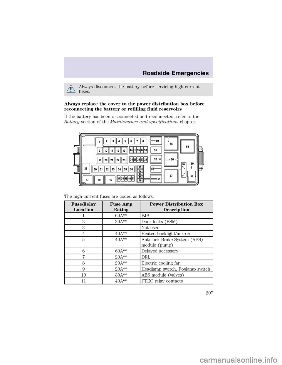
The high-current fuses are coded as follows:
Fuse/Relay
LocationFuse Amp
RatingPower Distribution Box
Description
1 60A** PJB
2 30A** Door locks (BSM)
3 — Not used
4 40A** Heated backlight/mirrors
5 40A** Anti-lock Brake System (ABS)
module (pump)
6 60A** Delayed accessory
7 20A** DRL
8 20A** Electric cooling fan
9 20A** Headlampswitch, Foglampswitch
10 30A** ABS module (valves)
11 40A** PTEC relay contacts
Roadside Emergencies
207