LINCOLN CONTINENTAL 2001 Owners Manual
Manufacturer: LINCOLN, Model Year: 2001, Model line: CONTINENTAL, Model: LINCOLN CONTINENTAL 2001Pages: 224, PDF Size: 1.82 MB
Page 131 of 224

These guidelines are designed to ensure that your transmission is not
damaged due to insufficient lubrication.
All Front Wheel Drive (FWD) vehicles
An example of recreational towing is towing your vehicle behind a
Motorhome. The following recreational towing guidelines are designed to
ensure that your transmission is not damaged. It is not recommended to
tow front wheel drive vehicles with the front drive wheels on the ground.
It is recommended to tow your vehicle with the drive wheels on a dolly
or two wheel car hauling trailer.
In case of a roadside emergency with a disabled vehicle (without access
to wheel dollies, car hauling trailer or flatbed transport vehicle) your
vehicle can be flat towed (all wheels on the ground) under the following
conditions:
²Place the transmission in N (Neutral).
²Maximum speed is 56 km/h (35 mph).
²Maximum distance is 80 km (50 miles).
Driving
131
Page 132 of 224
GETTING ROADSIDE ASSISTANCE
To fully assist you should you have a vehicle concern, Ford offers a
complimentary roadside assistance program. This program is separate
from the New Vehicle Limited Warranty. The service is available:
²24±hours, seven days a week
²for the Basic warranty period (Canada) or New Vehicle Limited
Warranty period (U.S.) of three years or 60 000 km (36 000 miles),
whichever comes first on Ford and Mercury vehicles, and four years or
80 000 km (50 000 miles) on Lincoln vehicles
Roadside assistance will cover:
²changing a flat tire
²jump-starts
²lock-out assistance
²fuel delivery
²towing of your disabled vehicle up to 56.3 kms (35 miles) from the
point of pickup (this can include to the nearest Ford dealership, or
your selling dealer if within the specified distance.) One tow per
disablement. Even non-warranty related tows, like accidents or getting
stuck in the mud or snow, are covered (some exclusions apply, such
as impound towing or repossession).
Using roadside assistance
Complete the roadside assistance identification card and place it in your
wallet for quick reference. In the United States, this card is found in the
Owner Guide portfolio in the glove compartment in Ford vehicles and is
mailed to you if you own a Mercury or Lincoln. In Canada, the card is
found in the Roadside Assistance book in the glove compartment.
To receive roadside assistance in the United States for Ford or Mercury
vehicles, call 1±800±241±3673 or if you own a Lincoln vehicle, call
1±800±521±4140. In Canada call 1±800±665±2006.
Should you need to arrange roadside assistance for yourself, Ford will
reimburse a reasonable amount. To obtain information about
reimbursement, call 1±800±241±3673 in the United States for Ford or
Mercury vehicles; or if you own a Lincoln vehicle, call 1±800±521±4140.
Call 1±800±665±2006 in Canada.
Roadside emergencies
132
Page 133 of 224
Roadside coverage beyond basic warranty
In the United States, you may purchase additional roadside assistance
coverage beyond this period through the Ford Auto Club by contacting
your Ford or Lincoln Mercury dealer.
Similarly in Canada, you may purchase additional coverage beyond the
basic coverage period by consulting the Ford Roadside Assistance Club
brochure or by calling 1±877±294±CLUB (1±877±294±2582).
HAZARD FLASHER
Use only in an emergency to warn traffic of vehicle breakdown,
approaching danger, etc. The hazard flashers can be operated when the
ignition is off.
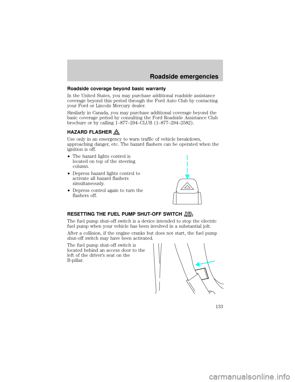
²The hazard lights control is
located on top of the steering
column.
²Depress hazard lights control to
activate all hazard flashers
simultaneously.
²Depress control again to turn the
flashers off.
RESETTING THE FUEL PUMP SHUT-OFF SWITCH
FUEL
RESET
The fuel pump shut-off switch is a device intended to stop the electric
fuel pump when your vehicle has been involved in a substantial jolt.
After a collision, if the engine cranks but does not start, the fuel pump
shut-off switch may have been activated.
The fuel pump shut-off switch is
located behind an access door to the
left of the driver's seat on the
B-pillar.
Roadside emergencies
133
Page 134 of 224
Use the following procedure to reset the fuel pump shut-off switch.
1. Turn the ignition to the OFF position.
2. Check the fuel system for leaks.
3. If no fuel leak is apparent, reset the fuel pump shut-off switch by
pushing in on the reset button.
4. Turn the ignition to the ON position. Pause for a few seconds and
return the key to the OFF position.
5. Make a further check for leaks in the fuel system.
FUSES AND RELAYS
Fuses
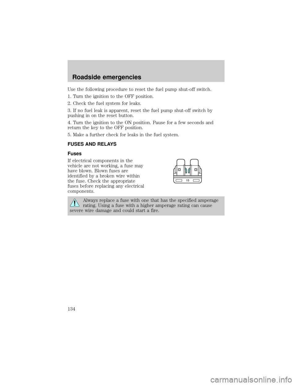
If electrical components in the
vehicle are not working, a fuse may
have blown. Blown fuses are
identified by a broken wire within
the fuse. Check the appropriate
fuses before replacing any electrical
components.
Always replace a fuse with one that has the specified amperage
rating. Using a fuse with a higher amperage rating can cause
severe wire damage and could start a fire.
15
Roadside emergencies
134
Page 135 of 224
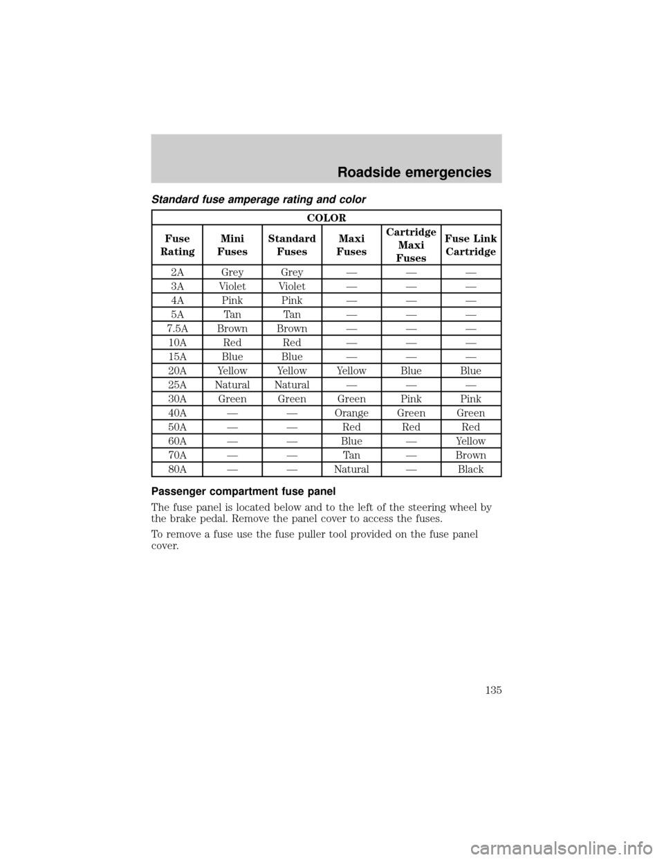
Standard fuse amperage rating and color
COLOR
Fuse
RatingMini
FusesStandard
FusesMaxi
FusesCartridge
Maxi
FusesFuse Link
Cartridge
2A Grey Grey Ð Ð Ð
3A Violet Violet Ð Ð Ð
4A Pink Pink Ð Ð Ð
5A Tan Tan Ð Ð Ð
7.5A Brown Brown Ð Ð Ð
10A Red Red Ð Ð Ð
15A Blue Blue Ð Ð Ð
20A Yellow Yellow Yellow Blue Blue
25A Natural Natural Ð Ð Ð
30A Green Green Green Pink Pink
40A Ð Ð Orange Green Green
50A Ð Ð Red Red Red
60A Ð Ð Blue Ð Yellow
70A Ð Ð Tan Ð Brown
80A Ð Ð Natural Ð Black
Passenger compartment fuse panel
The fuse panel is located below and to the left of the steering wheel by
the brake pedal. Remove the panel cover to access the fuses.
To remove a fuse use the fuse puller tool provided on the fuse panel
cover.
Roadside emergencies
135
Page 136 of 224
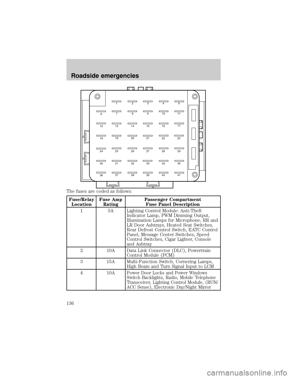
The fuses are coded as follows:
Fuse/Relay
LocationFuse Amp
RatingPassenger Compartment
Fuse Panel Description
1 5A Lighting Control Module: Anti-Theft
Indicator Lamp, PWM Dimming Output,
Illumination Lamps for Microphone, RR and
LR Door Ashtrays, Heated Seat Switches,
Rear Defrost Control Switch, EATC Control
Panel, Message Center Switches, Speed
Control Switches, Cigar Lighter, Console
and Ashtray
2 10A Data Link Connector (DLC), Powertrain
Control Module (PCM)
3 15A Multi-Function Switch, Cornering Lamps,
High Beam and Turn Signal Input to LCM
4 10A
Power Door Locks and Power Windows
Switch Backlights, Radio, Mobile Telephone
Transceiver, Lighting Control Module, (RUN/
ACC Sense), Electronic Day/Night Mirror
12345
7891011
17
13 14 15 16
19 20 21
25 26 27 28 29
31 30
36
6
12
18
24
32
33 34 35
37 38 39 40 41
2223
Roadside emergencies
136
Page 137 of 224
Fuse/Relay
LocationFuse Amp
RatingPassenger Compartment
Fuse Panel Description
5 10A Virtual Image Instrument Cluster, Lighting
Control Module (LCM RUN/START Sense),
Autolamp Light Sensor
6 10A Virtual Image Instrument Cluster, RF
Park/Turn Lamp
7 20A Power Point
8 20A Fuel Filler Door Release Switch, Trunk Lid
Relay
9 10A Air Bag Diagnostic Monitor, EATC Module,
Blower Motor Relay
10 30A Windshield Wiper Motor, Windshield Wiper
Module
11 10A Ignition Coils, Radio Interference Capacitor,
PCM Power Relay, Passive Anti-Theft
System (PATS) Transceiver
12 10A Lighting Control Module
13 15A Lighting Control Module (LCM): RF Turn
Lamp, Right Turn Indicator (VIC), RR Side
Marker Lamps, Tail Lamps, License Lamps,
LR Stop/Turn Lamps, Clock Illumination
14 20A Cigar Lighter
15 10A ABS Evac and Fill Connector
16 30A Moonroof Switch
17 Ð Not Used
18 10A Lighting Control Module
19 10A Lighting Control Module (LCM): Left
Headlamp, DRL
20 15A Multi-Function Switch: Flash to Pass, and
Hazard Warning Input to LCM
21 Ð Not Used
22 Ð Not Used
23 10A Digital Transmission Range Sensor
24 10A Virtual Image Cluster-LF Turn Indicator, LF
Turn Signal
Roadside emergencies
137
Page 138 of 224
Fuse/Relay
LocationFuse Amp
RatingPassenger Compartment
Fuse Panel Description
25 10A Lighting Control Module (LCM): Right
Headlamp
26 10A Virtual Image Instrument Cluster, EATC
Module
27 Ð Not Used
28 10A Shift Lock Actuator, Vehicle Dynamic
Module, Virtual Image Instrument Cluster,
Rear Window Defrost, Heated Seat Switch
Assembly, Low Tire Pressure Module
29 10A Radio
30 10A Heated Mirrors
31 15A Lighting Control Module (LCM): FCU,
Electronic Day/Night Mirror, RH and LH
Courtesy Lamp, Door Courtesy Lamps, RH
and LH Map Lamps, RR and LR Reading
Lamps, RH and LH Visor Lamps, Storage
Bin Lamps, Trunk Lid Lamp, Glove Box
Lamp, Light Sensor Amplifier
32 15A Speed Control DEAC. Switch, Brake On/Off
(BOO) Switch
33 Ð Not Used
34 15A Console Shift Illumination, A/C Clutch
Cycling Pressure Switch, A/C Clutch Relay
(DTR) Sensor, Intake Manifold Runner
Control, Backup Lamps
35 Ð Not Used
36 Ð Not Used
37 30A Subwoofer Amplifier, Radio
38 10A Analog Clock, CD Player, Mobile Telephone
Transceiver, RESCU
39 10A Power Door Locks, Power Seats, Power
Mirrors, Keyless Entry, LF Seat Module, LF
Door Module
40 10A Cornering Lamps
41 20A Door Locks
Roadside emergencies
138
Page 139 of 224
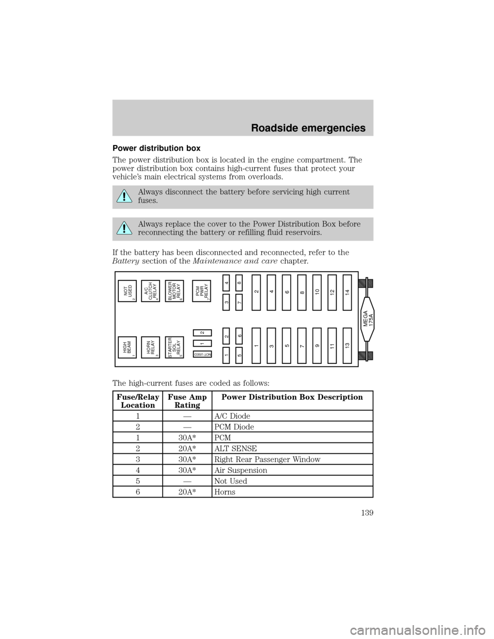
Power distribution box
The power distribution box is located in the engine compartment. The
power distribution box contains high-current fuses that protect your
vehicle's main electrical systems from overloads.
Always disconnect the battery before servicing high current
fuses.
Always replace the cover to the Power Distribution Box before
reconnecting the battery or refilling fluid reservoirs.
If the battery has been disconnected and reconnected, refer to the
Batterysection of theMaintenance and carechapter.
The high-current fuses are coded as follows:
Fuse/Relay
LocationFuse Amp
RatingPower Distribution Box Description
1 Ð A/C Diode
2 Ð PCM Diode
1 30A* PCM
2 20A* ALT SENSE
3 30A* Right Rear Passenger Window
4 30A* Air Suspension
5 Ð Not Used
6 20A* Horns
MEGA
175A
PCM
PWR
RELAY
12 3 4
8
7
6 5
12
4 3
5
7
9
1110
12
14 136
8NOT USED
7BLOWER
MOTOR
RELAY6A/C
CLUTCH
RELAY4NOT
USED2
HORN
RELAY3HIGH
BEAM1STARTER
SOL
RELAY5
12
Roadside emergencies
139
Page 140 of 224
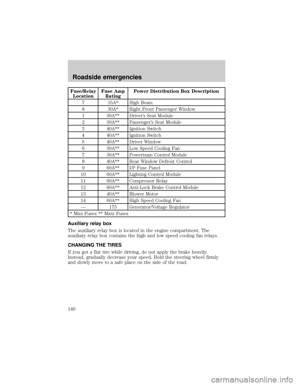
Fuse/Relay
LocationFuse Amp
RatingPower Distribution Box Description
7 15A* High Beam
8 30A* Right Front Passenger Window
1 30A** Driver's Seat Module
2 30A** Passenger's Seat Module
3 40A** Ignition Switch
4 40A** Ignition Switch
5 40A** Driver Window
6 30A** Low Speed Cooling Fan
7 30A** Powertrain Control Module
8 40A** Rear Window Defrost Control
9 60A** I/P Fuse Panel
10 60A** Lighting Control Module
11 60A** Compressor Relay
12 60A** Anti-Lock Brake Control Module
13 40A** Blower Motor
14 60A** High Speed Cooling Fan
Ð 175 Generator/Voltage Regulator
* Mini Fuses ** Maxi Fuses
Auxiliary relay box
The auxiliary relay box is located in the engine compartment. The
auxiliary relay box contains the high and low speed cooling fan relays.
CHANGING THE TIRES
If you get a flat tire while driving, do not apply the brake heavily.
Instead, gradually decrease your speed. Hold the steering wheel firmly
and slowly move to a safe place on the side of the road.
Roadside emergencies
140