Instrument cluster LINCOLN CONTINENTAL 2002 User Guide
[x] Cancel search | Manufacturer: LINCOLN, Model Year: 2002, Model line: CONTINENTAL, Model: LINCOLN CONTINENTAL 2002Pages: 240, PDF Size: 1.79 MB
Page 112 of 240
Conditions of operation
If... Then...
The driver's safety belt is not
buckled before the ignition
switch is turned to the ON
position...The safety belt warning light
illuminates 1-2 minutes and the
warning chime sounds 4-8 seconds.
The driver's safety belt is
buckled while the indicator
light is illuminated and the
warning chime is sounding...The safety belt warning light and
warning chime turn off.
The driver's safety belt is
buckled before the ignition
switch is turned to the ON
position...The safety belt warning light and
indicator chime remain off.
BeltMinder
The BeltMinder feature is a supplemental warning to the safety belt
warning function. This feature provides additional reminders to the
driver that the driver's safety belt is unbuckled by intermittently
sounding a chime and illuminating the safety belt warning lamp in the
instrument cluster.
If... Then...
The driver's safety belt is not
buckled before the vehicle has
reached at least 5 km/h (3
mph) and 1-2 minutes have
elapsed since the ignition
switch has been turned to
ON...The BeltMinder feature is activated -
the safety belt warning light
illuminates and the warning chime
sounds for 6 seconds every 30
seconds, repeating for approximately
5 minutes or until safety belt is
buckled.
The driver's safety belt is
buckled while the safety belt
indicator light is illuminated
and the safety belt warning
chime is sounding...The BeltMinder feature will not
activate.
Seating and Safety Restraints
112
Page 121 of 240
The SRS consists of:
²driver and passenger air bag modules (which include the inflators and
air bags)
²one or more impact and safing sensors
²a readiness light and tone
²a diagnostic module
²and the electrical wiring which connects the components
The diagnostic module monitors its own internal circuits and the
supplemental air bag electrical system warning (including the impact
sensors), the system wiring, the air bag system readiness light, the air
bag back up power and the air bag ignitors.
Several air bag system components get hot after inflation. Do not
touch them after inflation.
If the air bag has deployed,the air bag will not function
again and must be replaced immediately.If the air bag is not
replaced, the unrepaired area will increase the risk of injury in a
collision.
Determining if the system is operational
The SRS uses a readiness light in the instrument cluster or a tone to
indicate the condition of the system. Refer toAir bag readinesssection
in theInstrument clusterchapter. Routine maintenance of the air bag is
not required.
A difficulty with the system is indicated by one or more of the following:
²The readiness light will either
flash or stay lit.
²The readiness light will not
illuminate immediately after
ignition is turned on.
²A series of five beeps will be heard. The tone pattern will repeat
periodically until the problem and/or light are repaired.
AIR
BAG
Seating and Safety Restraints
121
Page 124 of 240
Several air bag system
components get hot after
inflation. Do not touch them after
inflation.
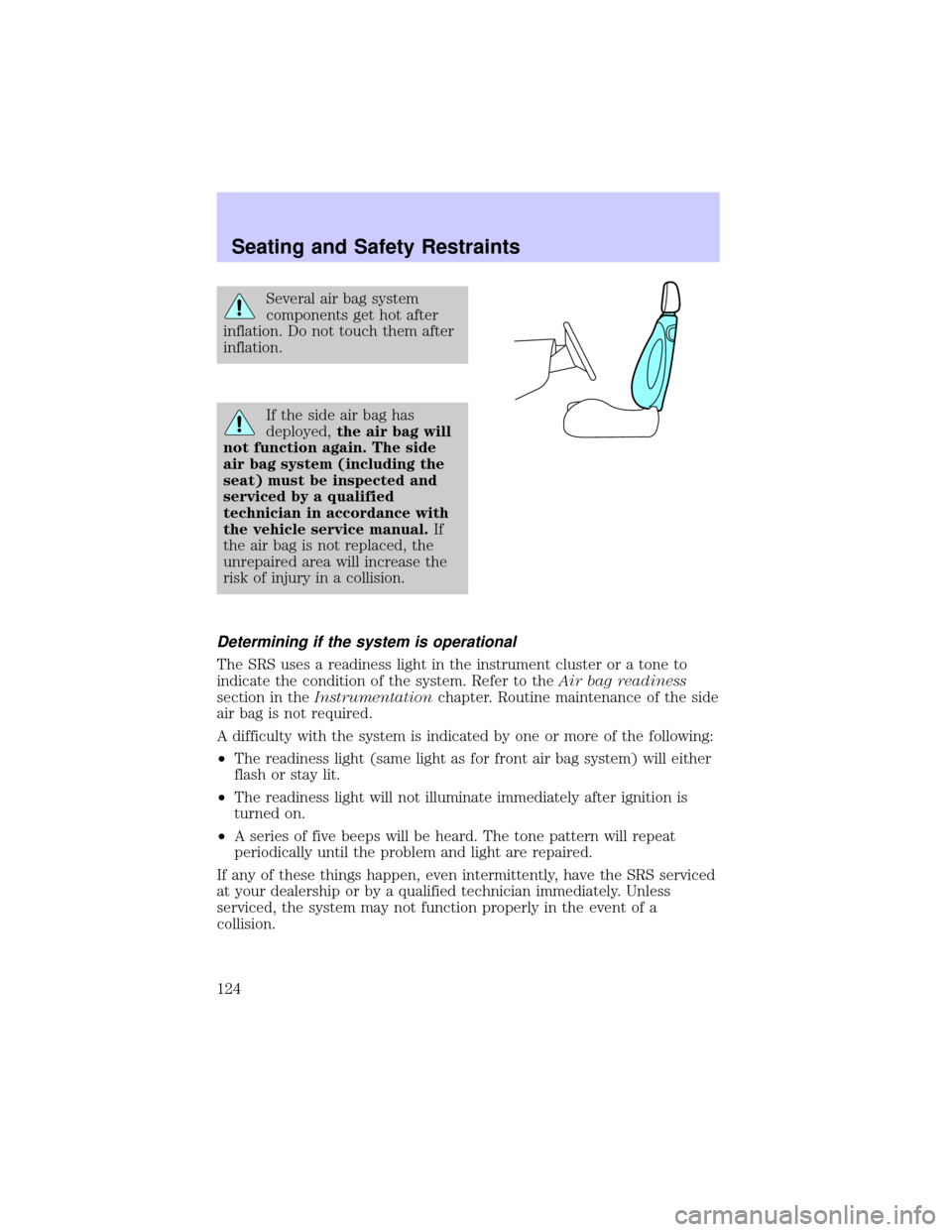
If the side air bag has
deployed,the air bag will
not function again. The side
air bag system (including the
seat) must be inspected and
serviced by a qualified
technician in accordance with
the vehicle service manual.If
the air bag is not replaced, the
unrepaired area will increase the
risk of injury in a collision.
Determining if the system is operational
The SRS uses a readiness light in the instrument cluster or a tone to
indicate the condition of the system. Refer to theAir bag readiness
section in theInstrumentationchapter. Routine maintenance of the side
air bag is not required.
A difficulty with the system is indicated by one or more of the following:
²The readiness light (same light as for front air bag system) will either
flash or stay lit.
²The readiness light will not illuminate immediately after ignition is
turned on.
²A series of five beeps will be heard. The tone pattern will repeat
periodically until the problem and light are repaired.
If any of these things happen, even intermittently, have the SRS serviced
at your dealership or by a qualified technician immediately. Unless
serviced, the system may not function properly in the event of a
collision.
Seating and Safety Restraints
124
Page 139 of 240
Using ABS
²In an emergency or when maximum efficiency from the four-wheel
ABS is required, apply continuous force on the brake. The four wheel
ABS will be activated immediately, thus allowing you to retain full
steering control of your vehicle and, providing there is sufficient
space, will enable you to avoid obstacles and bring the vehicle to a
controlled stop.
²The anti-lock system does not decrease the time necessary to apply
the brakes or always reduce stopping distance. Always leave enough
room between your vehicle and the vehicle in front of you to stop.
²We recommend that you familiarize yourself with this braking
technique. However, avoid taking any unnecessary risks.
ABS warning lampABS
TheABSwarning lamp in the instrument cluster momentarily illuminates
when the ignition is turned to the ON position. If the light does not
illuminate momentarily at start up, remains on or continues to flash, the
ABS needs to be serviced.
With the ABS light on, the anti-lock
brake system is disabled and normal
braking is still effective unless the
brake warning light also remains
illuminated with parking brake
released. (If your brake warning lamp illuminates, have your vehicle
serviced immediately.)
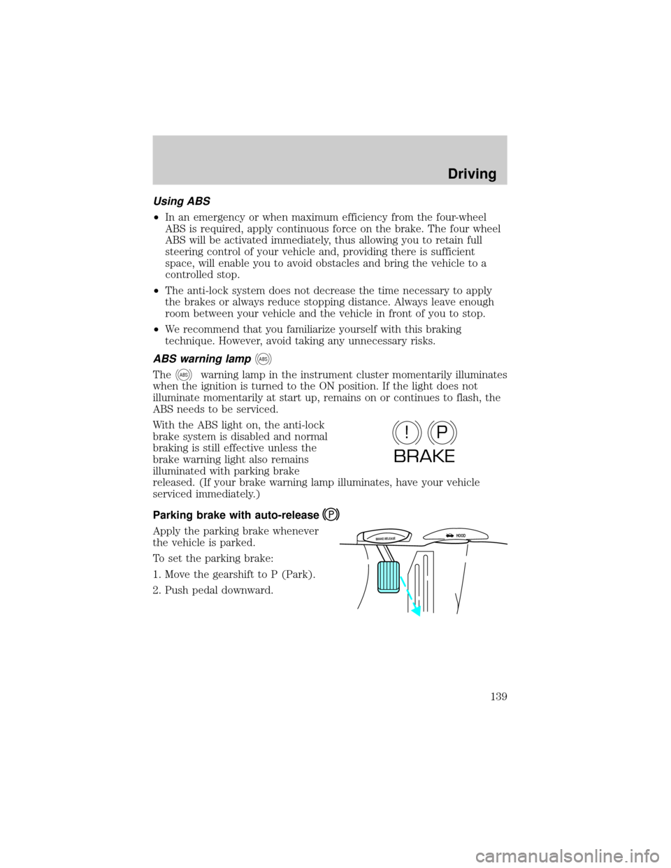
Parking brake with auto-release
Apply the parking brake whenever
the vehicle is parked.
To set the parking brake:
1. Move the gearshift to P (Park).
2. Push pedal downward.
P!
BRAKE
BRAKE RELEASEHOOD
Driving
139
Page 140 of 240
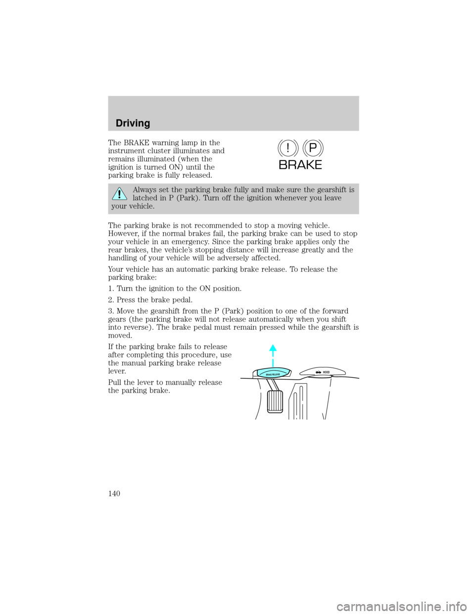
The BRAKE warning lamp in the
instrument cluster illuminates and
remains illuminated (when the
ignition is turned ON) until the
parking brake is fully released.
Always set the parking brake fully and make sure the gearshift is
latched in P (Park). Turn off the ignition whenever you leave
your vehicle.
The parking brake is not recommended to stop a moving vehicle.
However, if the normal brakes fail, the parking brake can be used to stop
your vehicle in an emergency. Since the parking brake applies only the
rear brakes, the vehicle's stopping distance will increase greatly and the
handling of your vehicle will be adversely affected.
Your vehicle has an automatic parking brake release. To release the
parking brake:
1. Turn the ignition to the ON position.
2. Press the brake pedal.
3. Move the gearshift from the P (Park) position to one of the forward
gears (the parking brake will not release automatically when you shift
into reverse). The brake pedal must remain pressed while the gearshift is
moved.
If the parking brake fails to release
after completing this procedure, use
the manual parking brake release
lever.
Pull the lever to manually release
the parking brake.
P!
BRAKE
BRAKE RELEASEHOOD
Driving
140
Page 159 of 240
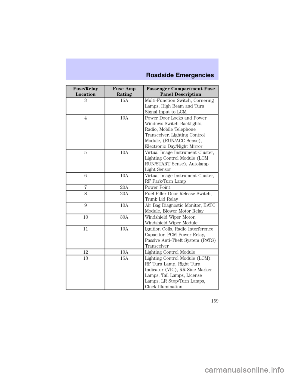
Fuse/Relay
LocationFuse Amp
RatingPassenger Compartment Fuse
Panel Description
3 15A Multi-Function Switch, Cornering
Lamps, High Beam and Turn
Signal Input to LCM
4 10A Power Door Locks and Power
Windows Switch Backlights,
Radio, Mobile Telephone
Transceiver, Lighting Control
Module, (RUN/ACC Sense),
Electronic Day/Night Mirror
5 10A Virtual Image Instrument Cluster,
Lighting Control Module (LCM
RUN/START Sense), Autolamp
Light Sensor
6 10A Virtual Image Instrument Cluster,
RF Park/Turn Lamp
7 20A Power Point
8 20A Fuel Filler Door Release Switch,
Trunk Lid Relay
9 10A Air Bag Diagnostic Monitor, EATC
Module, Blower Motor Relay
10 30A Windshield Wiper Motor,
Windshield Wiper Module
11 10A Ignition Coils, Radio Interference
Capacitor, PCM Power Relay,
Passive Anti-Theft System (PATS)
Transceiver
12 10A Lighting Control Module
13 15A Lighting Control Module (LCM):
RF Turn Lamp, Right Turn
Indicator (VIC), RR Side Marker
Lamps, Tail Lamps, License
Lamps, LR Stop/Turn Lamps,
Clock Illumination
Roadside Emergencies
159
Page 160 of 240
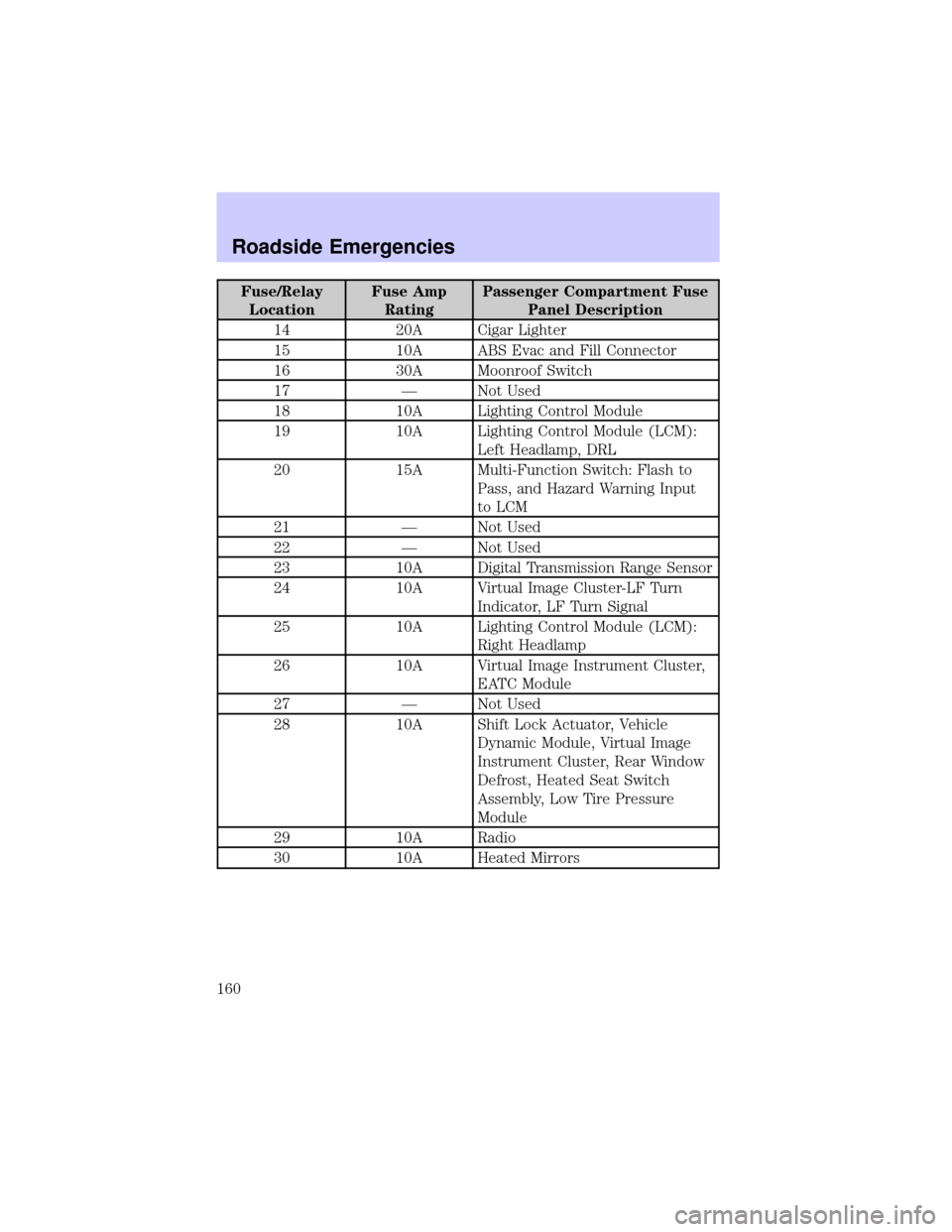
Fuse/Relay
LocationFuse Amp
RatingPassenger Compartment Fuse
Panel Description
14 20A Cigar Lighter
15 10A ABS Evac and Fill Connector
16 30A Moonroof Switch
17 Ð Not Used
18 10A Lighting Control Module
19 10A Lighting Control Module (LCM):
Left Headlamp, DRL
20 15A Multi-Function Switch: Flash to
Pass, and Hazard Warning Input
to LCM
21 Ð Not Used
22 Ð Not Used
23 10A Digital Transmission Range Sensor
24 10A Virtual Image Cluster-LF Turn
Indicator, LF Turn Signal
25 10A Lighting Control Module (LCM):
Right Headlamp
26 10A Virtual Image Instrument Cluster,
EATC Module
27 Ð Not Used
28 10A Shift Lock Actuator, Vehicle
Dynamic Module, Virtual Image
Instrument Cluster, Rear Window
Defrost, Heated Seat Switch
Assembly, Low Tire Pressure
Module
29 10A Radio
30 10A Heated Mirrors
Roadside Emergencies
160
Page 188 of 240
Do not use chemical solvents or strong detergents when cleaning
the steering wheel or instrument panel to avoid contamination of
the air bag system.
Cleaning the instrument cluster lens
Wipe the cluster area with a soft, damp cotton towel. Dry the area with a
clean, dry towel.
CLEANING SEATS EQUIPPED WITH SIDE AIR BAGS
Remove dust and loose dirt with a vacuum cleaner. In order to remove
stains and soil, clean with Extra Strength Upholstery Cleaner
(E8AZ-19523±AA).
Never saturate the seat covers with any cleaning solution.
Do not use chemical solvents or strong detergents when cleaning
the seat where the side air bag is mounted. Such products could
contaminate the side air bag system and affect performance of the side
air bag in a collision. The air bag may not function correctly and not
provide injury reduction benefits.
CLEANING THE INTERIOR FABRIC, CARPETS AND CLOTH SEATS
Remove dust and loose dirt with a vacuum cleaner. Remove light stains
and soil with Extra Strength Upholstery Cleaner (E8AZ-19523±AA).
Never saturate the seat covers with cleaning solution.
Do not use household cleaning products or glass cleaners, which
can stain and discolor the fabric and affect the flame retardent
abilities of the seat materials.
If grease or tar is present on the material, spot-clean the area first with
Spot and Stain Remover (F3AZ-19521±WA). Follow up by recleaning the
area with Extra Strength Upholstery Cleaner (E8AZ-19523±AA).
CLEANING LEATHER SEATS (IF EQUIPPED)
All Ford, Lincoln and Mercury vehicles with leather seating surfaces have
a clear, protective coating over the leather.
To clean the leather seats, simply use a soft cloth with Deluxe Leather
and Vinyl Cleaner (F2AZ-19521±WA). Dry the area with a soft cloth.
Cleaning
188
Page 208 of 240
Fuel quality
If you are experiencing starting, rough idle or hesitation driveability
problems during a cold start, try a different brand of ªPremiumº
unleaded gasoline. If the problems persist, see your dealer or a qualified
service technician.
It should not be necessary to add any aftermarket products to your fuel
tank if you continue to use high quality fuel of the recommended octane
rating. Aftermarket products could cause damage to the fuel system.
Repairs to correct the effects of using an aftermarket product in your
fuel may not be covered by your warranty.
Many of the world's automakers
issued the World-wide Fuel Charter
that recommends gasoline
specifications to provide improved
performance and emission control
system protection for your vehicle.
Gasolines that meet the World-wide
Fuel Charter should be used when
available. Ask your fuel supplier
about gasolines that meet the
World-wide Fuel Charter. In Canada,
look for fuels that display theAuto Makers' Choiceylogo.
Cleaner air
Ford endorses the use of reformulated ªcleaner-burningº gasolines to
improve air quality.
Running out of fuel
Avoid running out of fuel because this situation may have an adverse
affect on powertrain components.
If you have run out of fuel:
²You may need to cycle the ignition from OFF to ON several times after
refueling, to allow the fuel system to pump the fuel from the tank to
the engine.
²The
indicator may come on. For more information on the
ªService Engine Soonº indicator, refer to theInstrument Cluster
chapter.
Maintenance and Specifications
208
Page 213 of 240
If other than Ford, Motorcraft or Ford-authorized parts are used for
maintenance replacements or for service of components affecting
emission control, such non-Ford parts should be equivalent to genuine
Ford Motor Company parts in performance and durability.
Do not park, idle, or drive your vehicle in dry grass or other dry
ground cover. The emission system heats up the engine
compartment and exhaust system, which can start a fire.
Illumination of the ªService Engine Soonº light, charging system warning
light or the temperature warning light, fluid leaks, strange odors, smoke
or loss of engine power, could indicate that the emission control system
is not working properly.
Exhaust leaks may result in entry of harmful and potentially
lethal fumes into the passenger compartment.
Do not make any unauthorized changes to your vehicle or engine. By
law, vehicle owners and anyone who manufactures, repairs, services,
sells, leases, trades vehicles, or supervises a fleet of vehicles are not
permitted to intentionally remove an emission control device or prevent
it from working. Information about your vehicle's emission system is on
the Vehicle Emission Control Information Decal located on or near the
engine. This decal identifies engine displacement and gives some tune up
specifications.
Please consult yourWarranty Guidefor complete emission warranty
information.
Readiness for Inspection/Maintenance (I/M) testing
In some localities, it may be a legal requirement to pass an I/M test of
the on-board diagnostics system. If your ªCheck Engine/Service Engine
Soonº light is on, refer to the description in theWarning lights and
chimessection of theInstrument Clusterchapter. Your vehicle may not
pass the I/M test with the ªCheck Engine/Service Engine Soonº light on.
If the vehicle's powertrain system or its battery has just been serviced,
the on-board diagnostics system is reset to a ªnot ready for I/M testº
condition. To ready the on-board diagnostics system for I/M testing, a
minimum of 30 minutes of city and highway driving is necessary as
described below:
²First, at least 10 minutes of driving on an expressway or highway.
Maintenance and Specifications
213