light LINCOLN CONTINENTAL 2002 User Guide
[x] Cancel search | Manufacturer: LINCOLN, Model Year: 2002, Model line: CONTINENTAL, Model: LINCOLN CONTINENTAL 2002Pages: 240, PDF Size: 1.79 MB
Page 31 of 240

CD AND CD CHANGER CARE
²Handle discs by their edges only. Never touch the playing surface.
²Do not expose discs to direct sunlight or heat sources for extended
periods of time.
²Do not insert more than one disc into each slot of the CD changer
magazine.
Do not insert any promotional (odd shaped or sized) discs, or
discs with removable labels into the CD player as jamming may
occur.
CLEANING CASSETTE PLAYER
Clean the tape player head with a cassette cleaning cartridge after 10 to
12 hours of play in order to maintain the best sound and operation.
CASSETTE AND CASSETTE PLAYER CARE
²Use only cassettes that are 90 minutes long or less.
²Do not expose tapes to direct sunlight, high humidity, extreme heat or
extreme cold. Allow tapes that may have been exposed to extreme
temperatures to reach a moderate temperature before playing.
²Tighten very loose tapes by inserting a finger or pencil into the hole
and turning the hub.
²Remove loose labels before inserting tapes.
²Do not leave tapes in the cassette player for a long time when not
being played.
RADIO FREQUENCY INFORMATION
The Federal Communications Commission (FCC) and the Canadian Radio
and Telecommunications Commission(CRTC) establish the frequencies
AM and FM stations may use for their broadcasts. Allowable frequencies
are:
AM 530, 540±1600, 1610 kHz
FM 87.7, 87.9±107.7, 107.9 MHz
Not all frequencies are used in a given area.
Entertainment Systems
31
Page 32 of 240

RADIO RECEPTION FACTORS
Three factors can affect radio reception:
²Distance/strength.The further an FM signal travels, the weaker it is.
The listenable range of the average FM station is approximately 40 km
(24 miles). This range can be affected by ªsignal modulation.º Signal
modulation is a process radio stations use to increase their
strength/volume relative to other stations.
²Terrain.Hills, mountains and tall buildings between your vehicle's
antenna and the radio station signal can cause FM reception problems.
Static can be caused on AM stations by power lines, electric fences,
traffic lights and thunderstorms. Moving away from an interfering
structure (out of its ªshadowº) returns your reception to normal.
²Station overload.Weak signals are sometimes captured by stronger
signals when you pass a broadcast tower. A stronger signal may
temporarily overtake a weaker signal and play while the weak station
frequency is displayed.
The audio system automatically switches to single channel reception if it
will improve the reception of a station normally received in stereo.
AUDIO SYSTEM WARRANTIES AND SERVICE
Refer to theWarranty Guidefor audio system warranty information.
If service is necessary, see your dealer or a qualified technician.
Entertainment Systems
32
Page 36 of 240
²MAX A/C-Uses recirculated air to cool the vehicle. The temperature
display will remain unchanged and air will be cooled based on the
selected temerature. To exit, press AUTOMATIC or any other override
controls. MAX A/C is noisier than normal A/C but more economical
and will cool the inside of the vehicle faster. Airflow is from the
instrument panel registers. This mode can also be used to prevent
undesirable odors from entering the vehicle.
²
(Panel) -Distributes outside air through the instrument panel
registers. However, the air cannot be cooled below the outside
temperature because the air conditioning does not operate in this
mode.
²
(Panel and floor) -Distributes outside air through the instrument
panel registers and the floor ducts. Heating and air conditioning
capabilities are provided in this mode. The air will be heated or cooled
based on the temperature selection. For added customer comfort, the
air distributed through the floor ducts will be slightly warmer than the
air sent to the instrument panel registers.
²
(Floor)-Distributes outside air through the floor ducts. Heating
and air conditioning capabilities are provided in this mode.
²
(Floor and defrost)-Distributes outside air through the windshield
defroster ducts and the floor ducts. Heating and air conditioning
capabilities are provided in this mode. The air will be heated or cooled
based on the temperature selection. For added customer comfort, the
air distributed through the floor ducts will be slightly warmer than the
air sent to the windshield defroster ducts. If the temperature is about
6ÉC (43ÉF) or higher, the air conditioner will automatically dehumidify
the air to reduce fogging.
²FRONT
-Distributes outside air through the windshield defroster
ducts. It can be used to clear ice or fog from the windshield. If the
outside air temperature is about 6ÉC (43ÉF) or higher, the air
conditioner will automatically dehumidify the air to reduce fogging.
²OFF-Outside air is shut out and the fan will not operate. For short
periods of time only, use this mode to reduce undesirable odors from
entering the vehicle.
Climate Controls
36
Page 40 of 240
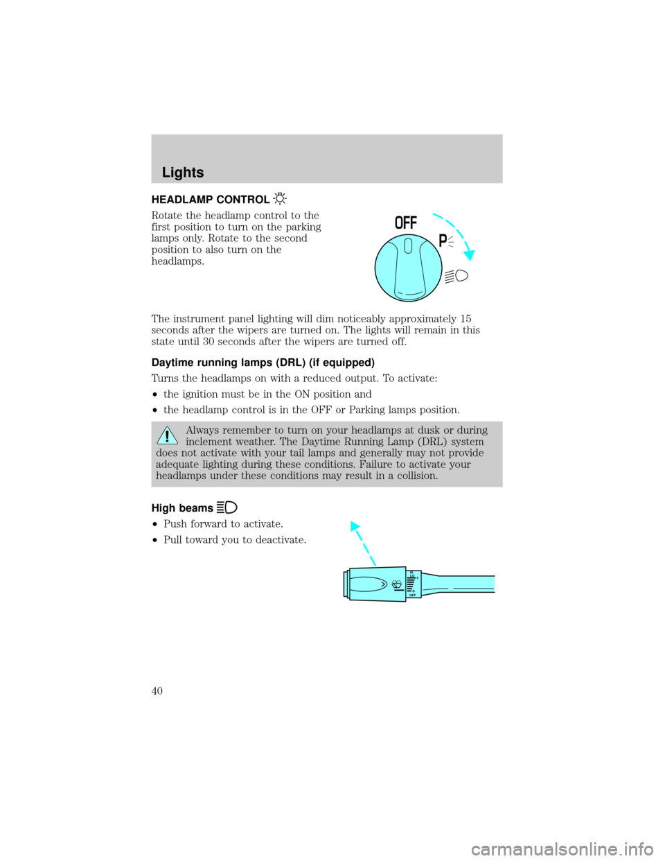
HEADLAMP CONTROL
Rotate the headlamp control to the
first position to turn on the parking
lamps only. Rotate to the second
position to also turn on the
headlamps.
The instrument panel lighting will dim noticeably approximately 15
seconds after the wipers are turned on. The lights will remain in this
state until 30 seconds after the wipers are turned off.
Daytime running lamps (DRL) (if equipped)
Turns the headlamps on with a reduced output. To activate:
²the ignition must be in the ON position and
²the headlamp control is in the OFF or Parking lamps position.
Always remember to turn on your headlamps at dusk or during
inclement weather. The Daytime Running Lamp (DRL) system
does not activate with your tail lamps and generally may not provide
adequate lighting during these conditions. Failure to activate your
headlamps under these conditions may result in a collision.
High beams
²Push forward to activate.
²Pull toward you to deactivate.
P
0FF
HI
LO
F
S
OFF
Lights
40
Page 41 of 240
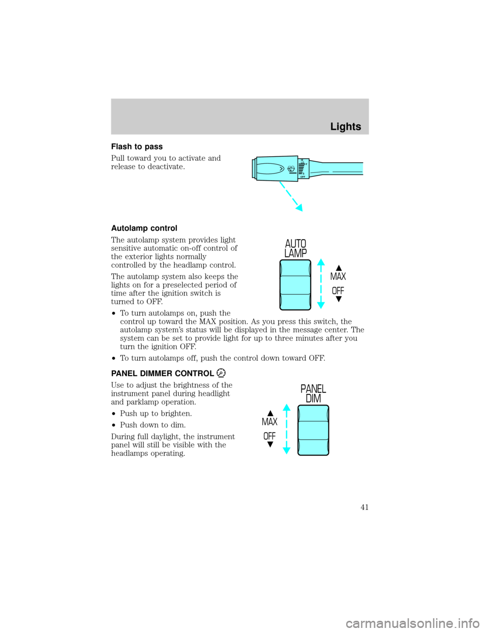
Flash to pass
Pull toward you to activate and
release to deactivate.
Autolamp control
The autolamp system provides light
sensitive automatic on-off control of
the exterior lights normally
controlled by the headlamp control.
The autolamp system also keeps the
lights on for a preselected period of
time after the ignition switch is
turned to OFF.
²To turn autolamps on, push the
control up toward the MAX position. As you press this switch, the
autolamp system's status will be displayed in the message center. The
system can be set to provide light for up to three minutes after you
turn the ignition OFF.
²To turn autolamps off, push the control down toward OFF.
PANEL DIMMER CONTROL
Use to adjust the brightness of the
instrument panel during headlight
and parklamp operation.
²Push up to brighten.
²Push down to dim.
During full daylight, the instrument
panel will still be visible with the
headlamps operating.
HI
LO
F
S
OFF
MAX
OFF
AUTO
LAMP
MAX
OFF
PANEL
DIM
Lights
41
Page 42 of 240
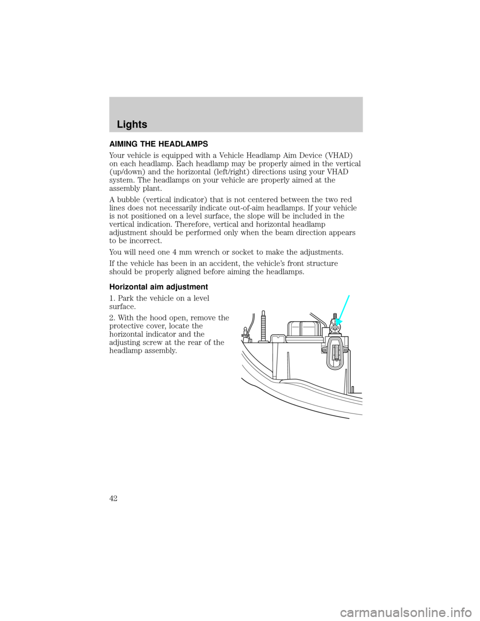
AIMING THE HEADLAMPS
Your vehicle is equipped with a Vehicle Headlamp Aim Device (VHAD)
on each headlamp. Each headlamp may be properly aimed in the vertical
(up/down) and the horizontal (left/right) directions using your VHAD
system. The headlamps on your vehicle are properly aimed at the
assembly plant.
A bubble (vertical indicator) that is not centered between the two red
lines does not necessarily indicate out-of-aim headlamps. If your vehicle
is not positioned on a level surface, the slope will be included in the
vertical indication. Therefore, vertical and horizontal headlamp
adjustment should be performed only when the beam direction appears
to be incorrect.
You will need one 4 mm wrench or socket to make the adjustments.
If the vehicle has been in an accident, the vehicle's front structure
should be properly aligned before aiming the headlamps.
Horizontal aim adjustment
1. Park the vehicle on a level
surface.
2. With the hood open, remove the
protective cover, locate the
horizontal indicator and the
adjusting screw at the rear of the
headlamp assembly.
U
D
Lights
42
Page 43 of 240
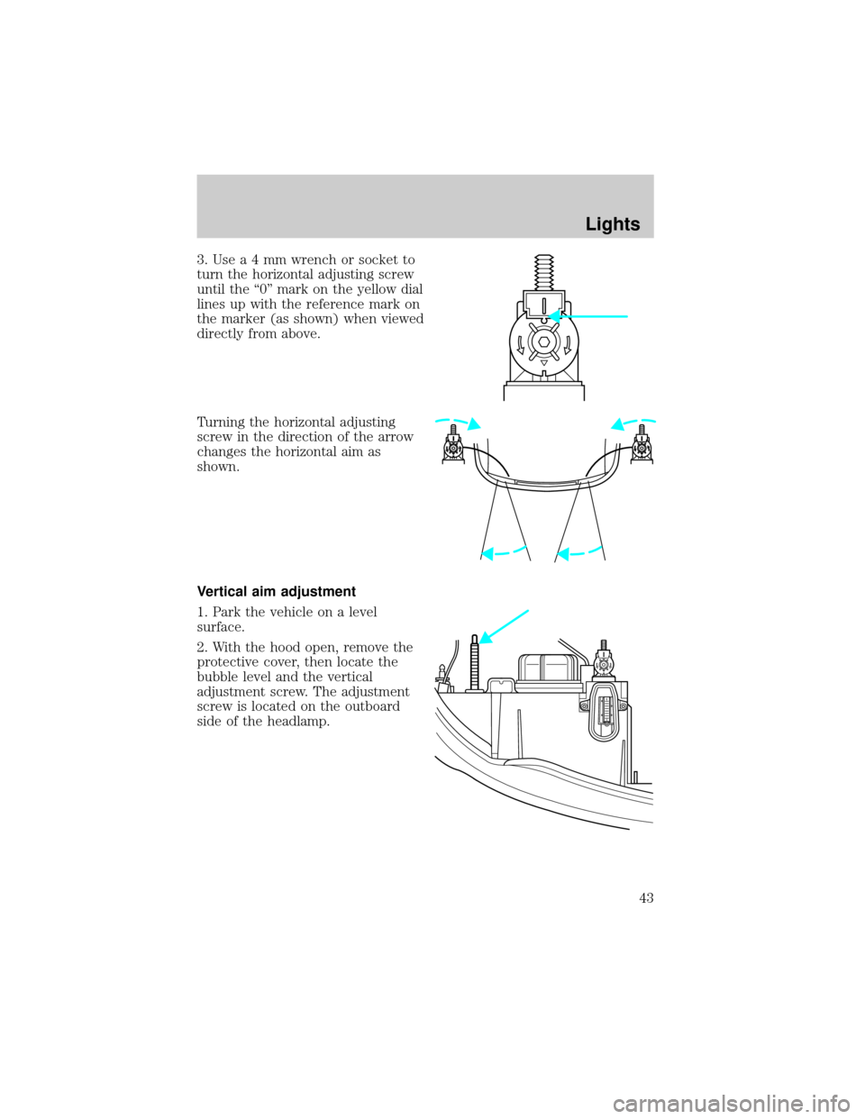
3.Usea4mmwrench or socket to
turn the horizontal adjusting screw
until the ª0º mark on the yellow dial
lines up with the reference mark on
the marker (as shown) when viewed
directly from above.
Turning the horizontal adjusting
screw in the direction of the arrow
changes the horizontal aim as
shown.
Vertical aim adjustment
1. Park the vehicle on a level
surface.
2. With the hood open, remove the
protective cover, then locate the
bubble level and the vertical
adjustment screw. The adjustment
screw is located on the outboard
side of the headlamp.
U
D
Lights
43
Page 44 of 240
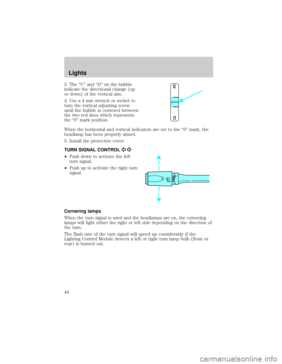
3. The ªUº and ªDº on the bubble
indicate the directional change (up
or down) of the vertical aim.
4.Usea4mmwrench or socket to
turn the vertical adjusting screw
until the bubble is centered between
the two red lines which represents
the ª0º mark position.
When the horizontal and vertical indicators are set to the ª0º mark, the
headlamp has been properly aimed.
5. Install the protective cover.
TURN SIGNAL CONTROL
²Push down to activate the left
turn signal.
²Push up to activate the right turn
signal.
Cornering lamps
When the turn signal is used and the headlamps are on, the cornering
lamps will light either the right or left side depending on the direction of
the turn.
The flash rate of the turn signal will speed up considerably if the
Lighting Control Module detects a left or right turn lamp bulb (front or
rear) is burned out.
D U
HI
LO
F
S
OFF
Lights
44
Page 45 of 240
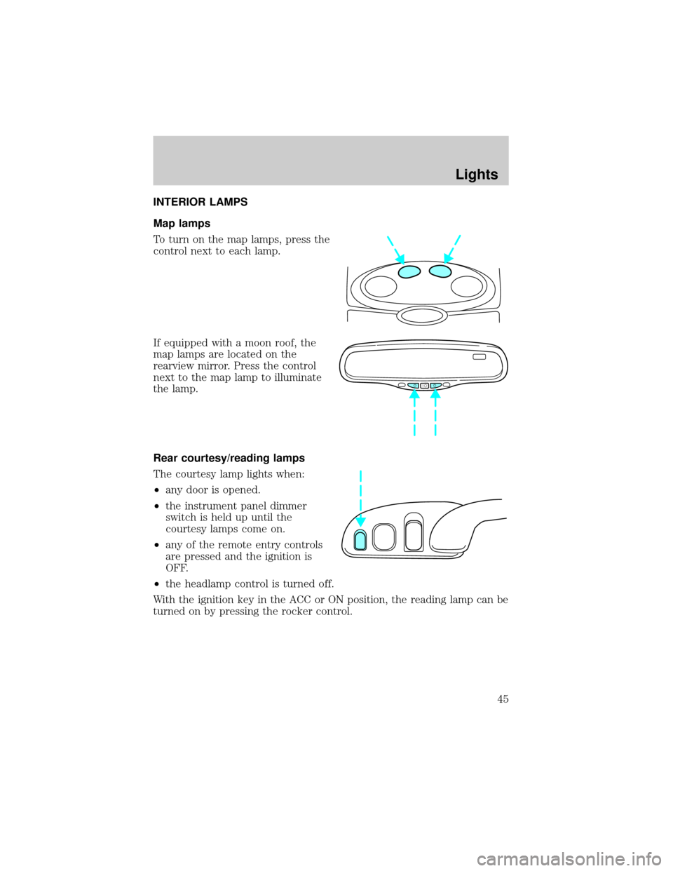
INTERIOR LAMPS
Map lamps
To turn on the map lamps, press the
control next to each lamp.
If equipped with a moon roof, the
map lamps are located on the
rearview mirror. Press the control
next to the map lamp to illuminate
the lamp.
Rear courtesy/reading lamps
The courtesy lamp lights when:
²any door is opened.
²the instrument panel dimmer
switch is held up until the
courtesy lamps come on.
²any of the remote entry controls
are pressed and the ignition is
OFF.
²the headlamp control is turned off.
With the ignition key in the ACC or ON position, the reading lamp can be
turned on by pressing the rocker control.
Lights
45
Page 46 of 240
BULBS
Replacing exterior bulbs
Check the operation of the following lamps frequently:
²Headlamps
²Tail lamps
²Brakelamps
²High-mount brakelamp
²Turn signals
²Backup lamps
²License plate lamp
Do not remove lamp bulbs unless they will be replaced immediately. If a
bulb is removed for an extended period of time, contaminants may enter
the lamp housings and affect performance.
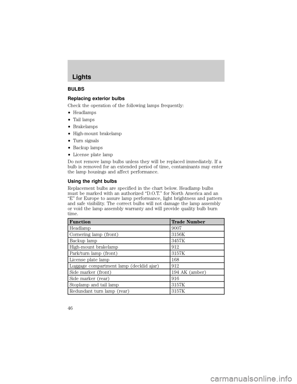
Using the right bulbs
Replacement bulbs are specified in the chart below. Headlamp bulbs
must be marked with an authorized ªD.O.T.º for North America and an
ªEº for Europe to assure lamp performance, light brightness and pattern
and safe visibility. The correct bulbs will not damage the lamp assembly
or void the lamp assembly warranty and will provide quality bulb burn
time.
Function Trade Number
Headlamp 9007
Cornering lamp (front) 3156K
Backup lamp 3457K
High-mount brakelamp 912
Park/turn lamp (front) 3157K
License plate lamp 168
Luggage compartment lamp (decklid ajar) 912
Side marker (front) 194 AK (amber)
Side marker (rear) 916
Stoplamp and tail lamp 3157K
Redundant turn lamp (rear) 3157K
Lights
46