Window lock LINCOLN CONTINENTAL 2002 Owners Manual
[x] Cancel search | Manufacturer: LINCOLN, Model Year: 2002, Model line: CONTINENTAL, Model: LINCOLN CONTINENTAL 2002Pages: 240, PDF Size: 1.79 MB
Page 1 of 240
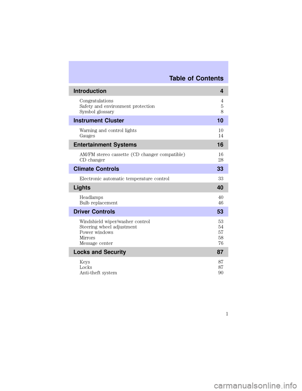
Introduction 4
Congratulations 4
Safety and environment protection 5
Symbol glossary 8
Instrument Cluster 10
Warning and control lights 10
Gauges 14
Entertainment Systems 16
AM/FM stereo cassette (CD changer compatible) 16
CD changer 28
Climate Controls 33
Electronic automatic temperature control 33
Lights 40
Headlamps 40
Bulb replacement 46
Driver Controls 53
Windshield wiper/washer control 53
Steering wheel adjustment 54
Power windows 57
Mirrors 58
Message center 76
Locks and Security 87
Keys 87
Locks 87
Anti-theft system 90
Table of Contents
1
Page 8 of 240
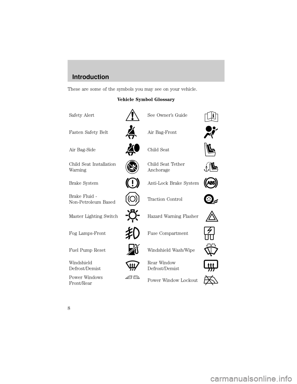
These are some of the symbols you may see on your vehicle.
Vehicle Symbol Glossary
Safety Alert
See Owner's Guide
Fasten Safety BeltAir Bag-Front
Air Bag-SideChild Seat
Child Seat Installation
WarningChild Seat Tether
Anchorage
Brake SystemAnti-Lock Brake System
Brake Fluid -
Non-Petroleum BasedTraction Control
Master Lighting SwitchHazard Warning Flasher
Fog Lamps-FrontFuse Compartment
Fuel Pump ResetWindshield Wash/Wipe
Windshield
Defrost/DemistRear Window
Defrost/Demist
Power Windows
Front/RearPower Window Lockout
Introduction
8
Page 38 of 240
²Under snowy or dirty weather conditions, your vehicle's climate
control system should be left in the OFF position when the vehicle is
parked. This allows the climate control system to be free from
contamination of outside pollutants.
²If your vehicle has been parked with the windows closed during warm
weather conditions, the air conditioner will perform more efficiently in
cooling the vehicle if driven for two or three minutes with the
windows open. This will force most of the hot, stale air out of the
vehicle. Once the vehicle has been ªaired outº, operate the climate
control system as desired.
²Don't put objects under the front seat that will interfere with the
airflow to the rear seats.
²Remove any snow, ice or leaves from the air intake area at the area at
the base of the windshield.
²Do not place objects over the defroster outlets. These objects can
block airflow and reduce your ability to see through your windshield.
Avoid placing small objects on top of the instrument panel. These
objects may fall down into the defroster outlets and block airflow, in
addition to damaging the climate control system.
To aid in side window defogging/demisting in cold weather conditions:
1. Select PANEL & FLOOR
2. Set the temperature control to full heat
3. Set the fan speed to HI
4. Direct the outer panel vents towards to side windows
To increase airflow to the outer panel vents, close the central panel
vents.
Do not place objects on top of the instrument panel, as these
objects may become projectiles in a collision or sudden stop.
Climate Controls
38
Page 57 of 240

Use only soft cups in the cupholder. Hard objects can injure you
in a collision.
POSITIVE RETENTION FLOOR MAT
Position the floor mat so that the
eyelet is over the pointed end of the
retention post and rotate forward to
lock in. Make sure that the mat does
not interfere with the operation of
the accelerator or the brake pedal.
To remove the floor mat, reverse the
installation procedure.
POWER WINDOWS
Press and pull the rocker switches to open and close windows.
²Press the top portion of the
rocker switch to open.
²Pull the top portion of the rocker
switch to close.
WINDOW
LOCK
WINDOW
LOCK
Driver Controls
57
Page 58 of 240
Express down
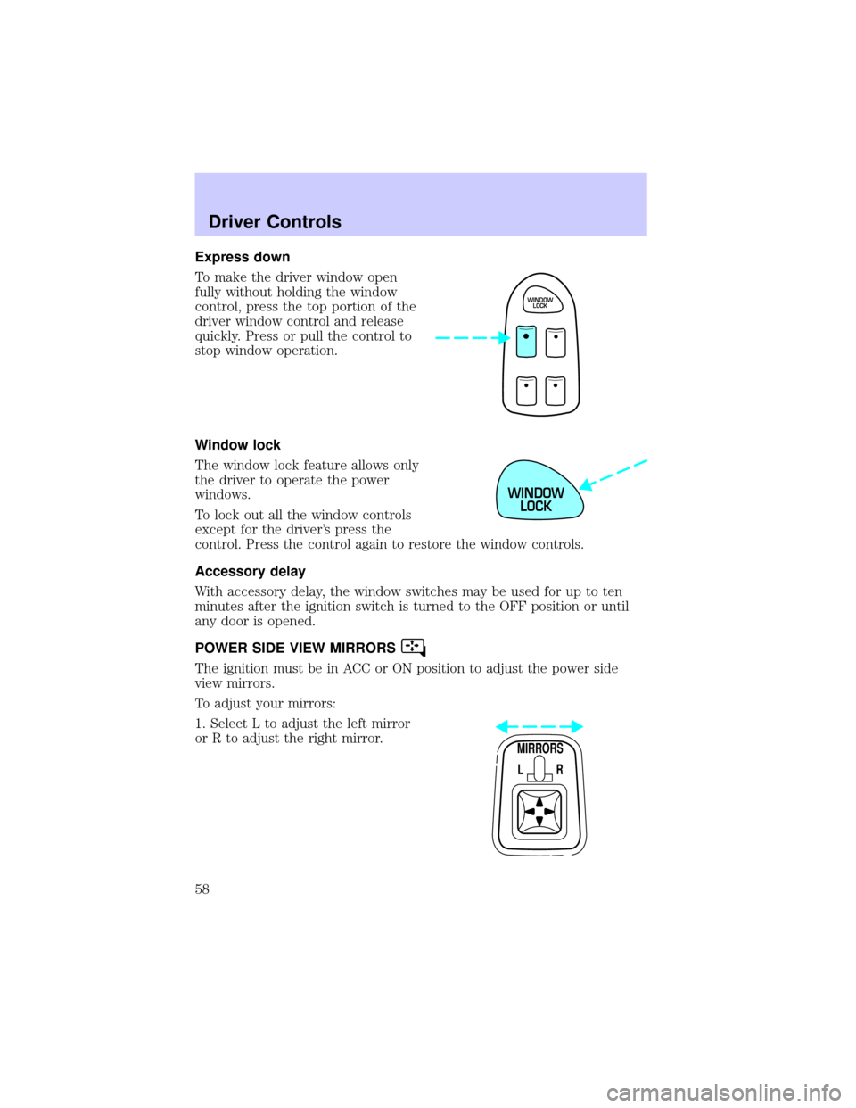
To make the driver window open
fully without holding the window
control, press the top portion of the
driver window control and release
quickly. Press or pull the control to
stop window operation.
Window lock
The window lock feature allows only
the driver to operate the power
windows.
To lock out all the window controls
except for the driver's press the
control. Press the control again to restore the window controls.
Accessory delay
With accessory delay, the window switches may be used for up to ten
minutes after the ignition switch is turned to the OFF position or until
any door is opened.
POWER SIDE VIEW MIRRORS
The ignition must be in ACC or ON position to adjust the power side
view mirrors.
To adjust your mirrors:
1. Select L to adjust the left mirror
or R to adjust the right mirror.
WINDOW
LOCK
WINDOW
LOCK
MIRRORS
L R
Driver Controls
58
Page 59 of 240

2. Move the control in the direction
you wish to tilt the mirror.
3. Return to the center position to lock mirrors in place.
Heated outside mirrors
Both mirrors are heated
automatically to remove ice, mist
and fog when the rear window
defrost is activated.
Do not remove ice from the mirrors
with a scraper or attempt to
readjust the mirror glass if it is
frozen in place. These actions could
cause damage to the glass and
mirrors.
Automatic dimming rear view mirror
Your vehicle is equipped with an inside rear view mirror and a driver's
outside mirror that has an auto-dimming function. The electronic
day/night mirrors will change from the normal state to the non-glare
state when bright lights (glare) reach the mirrors. When the inside rear
view mirror detects bright light from in front of or behind the vehicle,
the inside and driver side outside rear view mirrors will automatically
adjust (darken) to minimize glare.
MIRRORS
L R
Driver Controls
59
Page 83 of 240
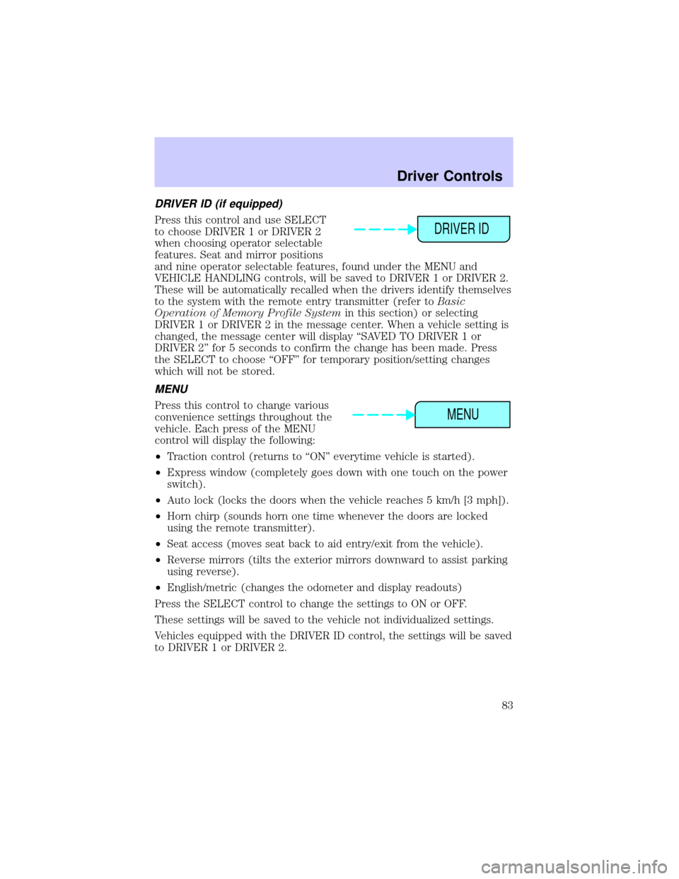
DRIVER ID (if equipped)
Press this control and use SELECT
to choose DRIVER 1 or DRIVER 2
when choosing operator selectable
features. Seat and mirror positions
and nine operator selectable features, found under the MENU and
VEHICLE HANDLING controls, will be saved to DRIVER 1 or DRIVER 2.
These will be automatically recalled when the drivers identify themselves
to the system with the remote entry transmitter (refer toBasic
Operation of Memory Profile Systemin this section) or selecting
DRIVER 1 or DRIVER 2 in the message center. When a vehicle setting is
changed, the message center will display ªSAVED TO DRIVER 1 or
DRIVER 2º for 5 seconds to confirm the change has been made. Press
the SELECT to choose ªOFFº for temporary position/setting changes
which will not be stored.
MENU
Press this control to change various
convenience settings throughout the
vehicle. Each press of the MENU
control will display the following:
²Traction control (returns to ªONº everytime vehicle is started).
²Express window (completely goes down with one touch on the power
switch).
²Auto lock (locks the doors when the vehicle reaches 5 km/h [3 mph]).
²Horn chirp (sounds horn one time whenever the doors are locked
using the remote transmitter).
²Seat access (moves seat back to aid entry/exit from the vehicle).
²Reverse mirrors (tilts the exterior mirrors downward to assist parking
using reverse).
²English/metric (changes the odometer and display readouts)
Press the SELECT control to change the settings to ON or OFF.
These settings will be saved to the vehicle not individualized settings.
Vehicles equipped with the DRIVER ID control, the settings will be saved
to DRIVER 1 or DRIVER 2.
DRIVER ID
MENU
Driver Controls
83
Page 159 of 240
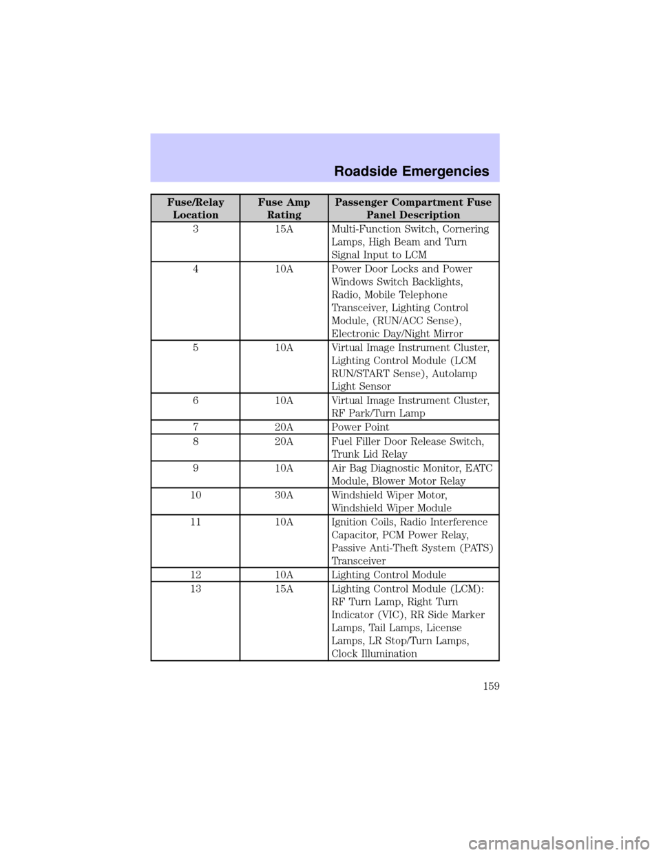
Fuse/Relay
LocationFuse Amp
RatingPassenger Compartment Fuse
Panel Description
3 15A Multi-Function Switch, Cornering
Lamps, High Beam and Turn
Signal Input to LCM
4 10A Power Door Locks and Power
Windows Switch Backlights,
Radio, Mobile Telephone
Transceiver, Lighting Control
Module, (RUN/ACC Sense),
Electronic Day/Night Mirror
5 10A Virtual Image Instrument Cluster,
Lighting Control Module (LCM
RUN/START Sense), Autolamp
Light Sensor
6 10A Virtual Image Instrument Cluster,
RF Park/Turn Lamp
7 20A Power Point
8 20A Fuel Filler Door Release Switch,
Trunk Lid Relay
9 10A Air Bag Diagnostic Monitor, EATC
Module, Blower Motor Relay
10 30A Windshield Wiper Motor,
Windshield Wiper Module
11 10A Ignition Coils, Radio Interference
Capacitor, PCM Power Relay,
Passive Anti-Theft System (PATS)
Transceiver
12 10A Lighting Control Module
13 15A Lighting Control Module (LCM):
RF Turn Lamp, Right Turn
Indicator (VIC), RR Side Marker
Lamps, Tail Lamps, License
Lamps, LR Stop/Turn Lamps,
Clock Illumination
Roadside Emergencies
159
Page 160 of 240
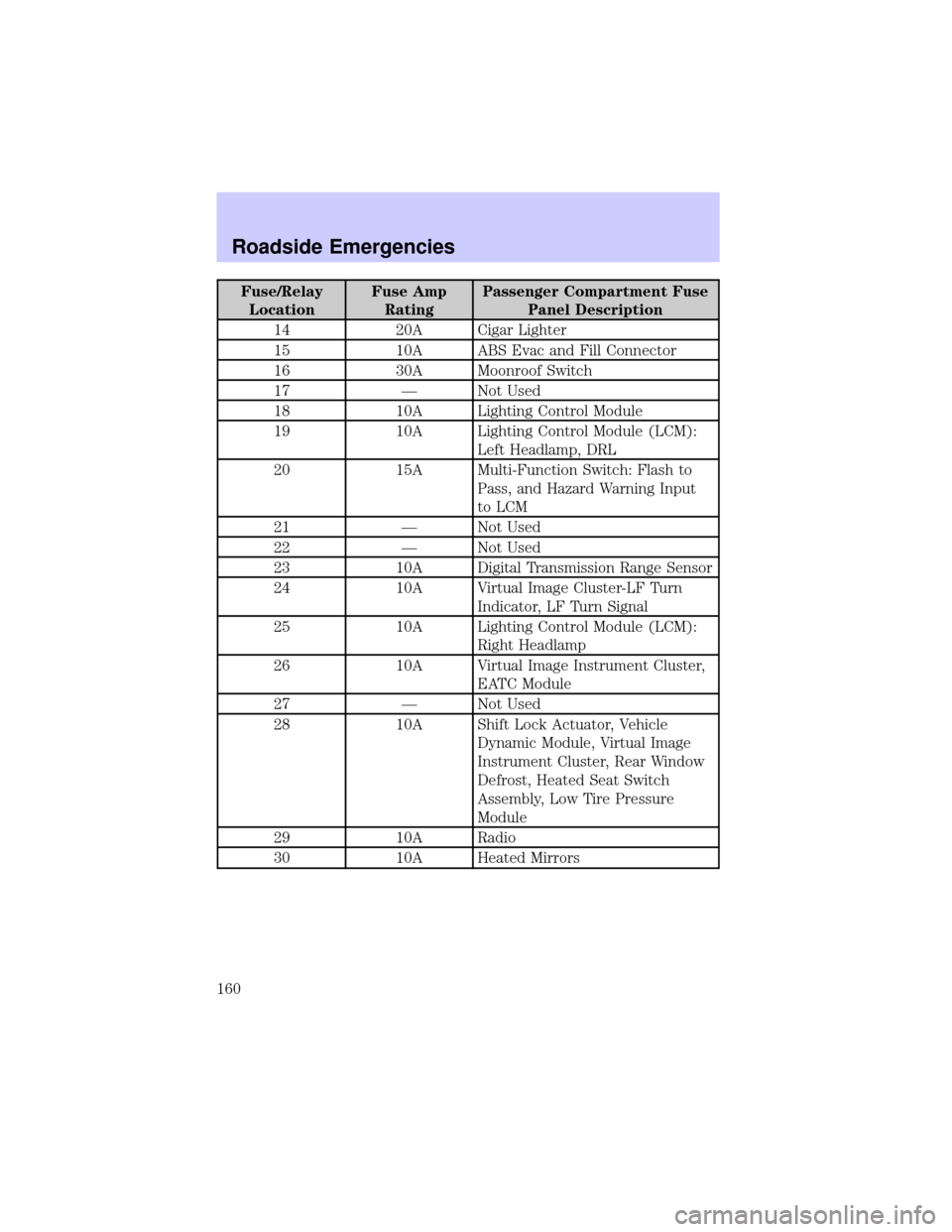
Fuse/Relay
LocationFuse Amp
RatingPassenger Compartment Fuse
Panel Description
14 20A Cigar Lighter
15 10A ABS Evac and Fill Connector
16 30A Moonroof Switch
17 Ð Not Used
18 10A Lighting Control Module
19 10A Lighting Control Module (LCM):
Left Headlamp, DRL
20 15A Multi-Function Switch: Flash to
Pass, and Hazard Warning Input
to LCM
21 Ð Not Used
22 Ð Not Used
23 10A Digital Transmission Range Sensor
24 10A Virtual Image Cluster-LF Turn
Indicator, LF Turn Signal
25 10A Lighting Control Module (LCM):
Right Headlamp
26 10A Virtual Image Instrument Cluster,
EATC Module
27 Ð Not Used
28 10A Shift Lock Actuator, Vehicle
Dynamic Module, Virtual Image
Instrument Cluster, Rear Window
Defrost, Heated Seat Switch
Assembly, Low Tire Pressure
Module
29 10A Radio
30 10A Heated Mirrors
Roadside Emergencies
160
Page 163 of 240
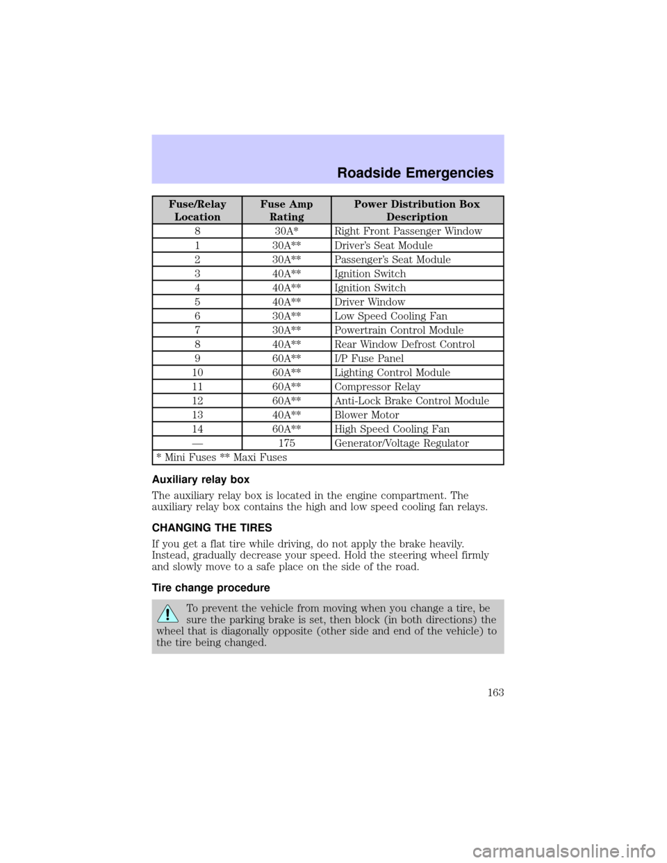
Fuse/Relay
LocationFuse Amp
RatingPower Distribution Box
Description
8 30A* Right Front Passenger Window
1 30A** Driver's Seat Module
2 30A** Passenger's Seat Module
3 40A** Ignition Switch
4 40A** Ignition Switch
5 40A** Driver Window
6 30A** Low Speed Cooling Fan
7 30A** Powertrain Control Module
8 40A** Rear Window Defrost Control
9 60A** I/P Fuse Panel
10 60A** Lighting Control Module
11 60A** Compressor Relay
12 60A** Anti-Lock Brake Control Module
13 40A** Blower Motor
14 60A** High Speed Cooling Fan
Ð 175 Generator/Voltage Regulator
* Mini Fuses ** Maxi Fuses
Auxiliary relay box
The auxiliary relay box is located in the engine compartment. The
auxiliary relay box contains the high and low speed cooling fan relays.
CHANGING THE TIRES
If you get a flat tire while driving, do not apply the brake heavily.
Instead, gradually decrease your speed. Hold the steering wheel firmly
and slowly move to a safe place on the side of the road.
Tire change procedure
To prevent the vehicle from moving when you change a tire, be
sure the parking brake is set, then block (in both directions) the
wheel that is diagonally opposite (other side and end of the vehicle) to
the tire being changed.
Roadside Emergencies
163