Cluster LINCOLN LS 2002 User Guide
[x] Cancel search | Manufacturer: LINCOLN, Model Year: 2002, Model line: LS, Model: LINCOLN LS 2002Pages: 288, PDF Size: 2.44 MB
Page 94 of 288
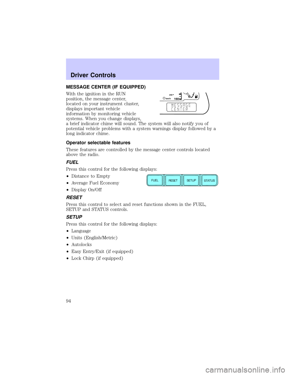
MESSAGE CENTER (IF EQUIPPED)
With the ignition in the RUN
position, the message center,
located on your instrument cluster,
displays important vehicle
information by monitoring vehicle
systems. When you change displays,
a brief indicator chime will sound. The system will also notify you of
potential vehicle problems with a system warnings display followed by a
long indicator chime.
Operator selectable features
These features are controlled by the message center controls located
above the radio.
FUEL
Press this control for the following displays:
²Distance to Empty
²Average Fuel Economy
²Display On/Off
RESET
Press this control to select and reset functions shown in the FUEL,
SETUP and STATUS controls.
SETUP
Press this control for the following displays:
²Language
²Units (English/Metric)
²Autolocks
²Easy Entry/Exit (if equipped)
²Lock Chirp (if equipped)
160240km/hE
FUEL
RESET
SETUP
STATUS
Driver Controls
94
Page 133 of 288
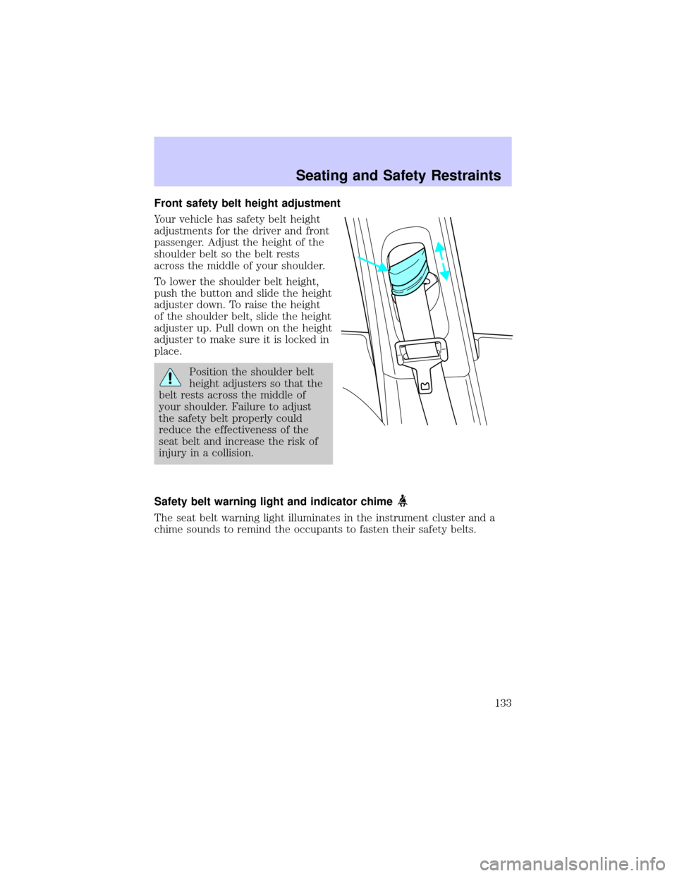
Front safety belt height adjustment
Your vehicle has safety belt height
adjustments for the driver and front
passenger. Adjust the height of the
shoulder belt so the belt rests
across the middle of your shoulder.
To lower the shoulder belt height,
push the button and slide the height
adjuster down. To raise the height
of the shoulder belt, slide the height
adjuster up. Pull down on the height
adjuster to make sure it is locked in
place.
Position the shoulder belt
height adjusters so that the
belt rests across the middle of
your shoulder. Failure to adjust
the safety belt properly could
reduce the effectiveness of the
seat belt and increase the risk of
injury in a collision.
Safety belt warning light and indicator chime
The seat belt warning light illuminates in the instrument cluster and a
chime sounds to remind the occupants to fasten their safety belts.
Seating and Safety Restraints
133
Page 134 of 288
Conditions of operation
If... Then...
The driver's safety belt is not
buckled before the ignition
switch is turned to the RUN
position...The safety belt warning light
illuminates 1-2 minutes and the
warning chime sounds 4-8 seconds.
The driver's safety belt is
buckled while the indicator
light is illuminated and the
warning chime is sounding...The safety belt warning light and
warning chime turn off.
The driver's safety belt is
buckled before the ignition
switch is turned to the RUN
position...The safety belt warning light and
indicator chime remain off.
BeltMinder
The BeltMinder feature is a supplemental warning to the safety belt
warning function. This feature provides additional reminders to the
driver that the driver's safety belt is unbuckled by intermittently
sounding a chime and illuminating the safety belt warning lamp in the
instrument cluster.
If... Then...
The driver's safety belt is not
buckled before the vehicle has
reached at least 5 km/h
(3 mph) and 1-2 minutes have
elapsed since the ignition
switch has been turned to
ON...The BeltMinder feature is activated -
the safety belt warning light
illuminates and the warning chime
sounds for 6 seconds every 30
seconds, repeating for approximately
5 minutes or until safety belt is
buckled.
The driver's safety belt is
buckled while the safety belt
indicator light is illuminated
and the safety belt warning
chime is sounding...The BeltMinder feature will not
activate.
The driver's safety belt is
buckled before the ignition
switch is turned to the ON
position...The BeltMinder feature will not
activate.
Seating and Safety Restraints
134
Page 143 of 288
²one or more impact and safing sensors
²a readiness light and tone
²and the electrical wiring which connects the components
The diagnostic module monitors its own internal circuits and the
supplemental air bag electrical system warning (including the impact
sensors), the system wiring, the air bag system readiness light, the air
bag back up power, the air bag ignitors and safety belt pretensioners.
Determining if the system is operational
The SRS uses a readiness light in the instrument cluster or a tone to
indicate the condition of the system. Refer to theAir bag readiness
section in theInstrument clusterchapter. Routine maintenance of the
air bag is not required.
Any difficulty with the system is indicated by one or more of the
following:
²The readiness light will either
flash or stay lit
²The readiness light will not
illuminate immediately after
ignition is turned to the RUN
position
²A series of five beeps will be heard. The tone pattern will repeat
periodically until the problem and/or light are repaired.
If any of these things happen, even intermittently, have the SRS serviced
at your dealership or by a qualified technician immediately. Unless
serviced, the system may not function properly in the event of a
collision.
Side air bag system
Do not place objects or mount equipment on or near the air bag
cover on the side of the seatbacks of the front seats or in front
seat areas that may come into contact with a deploying air bag. Failure
to follow these instructions may increase the risk of personal injury in
the event of a collision.
Seating and Safety Restraints
143
Page 145 of 288
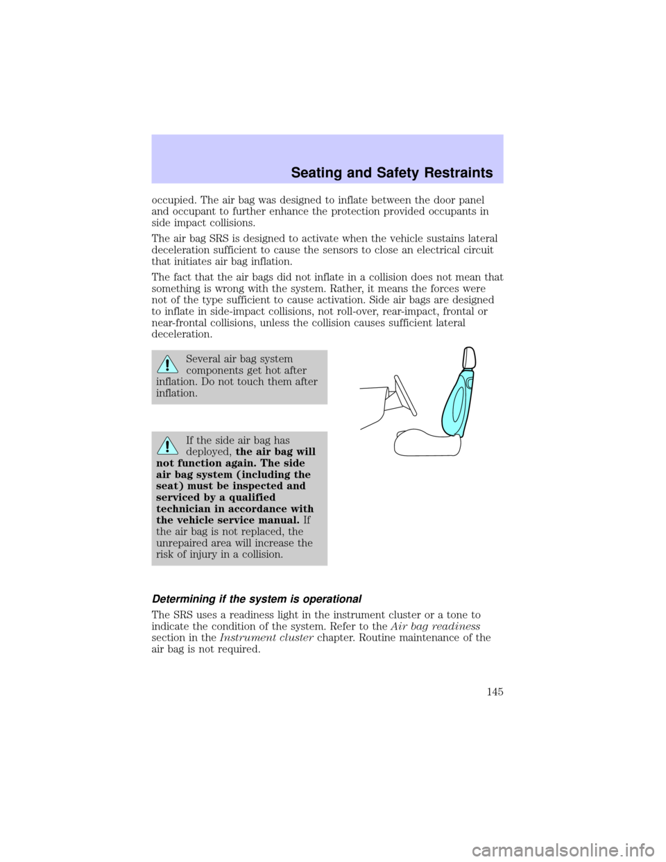
occupied. The air bag was designed to inflate between the door panel
and occupant to further enhance the protection provided occupants in
side impact collisions.
The air bag SRS is designed to activate when the vehicle sustains lateral
deceleration sufficient to cause the sensors to close an electrical circuit
that initiates air bag inflation.
The fact that the air bags did not inflate in a collision does not mean that
something is wrong with the system. Rather, it means the forces were
not of the type sufficient to cause activation. Side air bags are designed
to inflate in side-impact collisions, not roll-over, rear-impact, frontal or
near-frontal collisions, unless the collision causes sufficient lateral
deceleration.
Several air bag system
components get hot after
inflation. Do not touch them after
inflation.
If the side air bag has
deployed,the air bag will
not function again. The side
air bag system (including the
seat) must be inspected and
serviced by a qualified
technician in accordance with
the vehicle service manual.If
the air bag is not replaced, the
unrepaired area will increase the
risk of injury in a collision.
Determining if the system is operational
The SRS uses a readiness light in the instrument cluster or a tone to
indicate the condition of the system. Refer to theAir bag readiness
section in theInstrument clusterchapter. Routine maintenance of the
air bag is not required.
Seating and Safety Restraints
145
Page 162 of 288
ABS warning lampABS
TheABSwarning lamp in the instrument cluster momentarily illuminates
when the ignition is turned to the RUN position. If the light does not
illuminate momentarily at start up, remains on or continues to flash, the
ABS needs to be serviced.
With the ABS light on, the anti-lock
brake system is disabled and normal
braking is still effective unless the
brake warning light also remains
illuminated with parking brake
released. (If your brake warning lamp illuminates, have your vehicle
serviced immediately.)
Parking brake
Apply the parking brake whenever
the vehicle is parked. To set the
parking brake, apply the brake pedal
and pull the handle up as far as
possible.
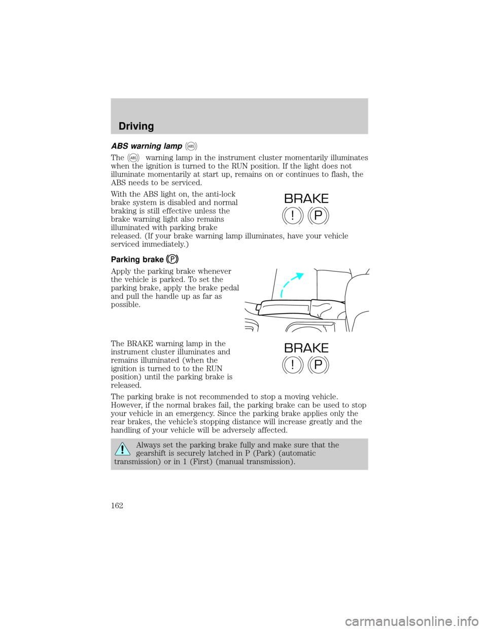
The BRAKE warning lamp in the
instrument cluster illuminates and
remains illuminated (when the
ignition is turned to to the RUN
position) until the parking brake is
released.
The parking brake is not recommended to stop a moving vehicle.
However, if the normal brakes fail, the parking brake can be used to stop
your vehicle in an emergency. Since the parking brake applies only the
rear brakes, the vehicle's stopping distance will increase greatly and the
handling of your vehicle will be adversely affected.
Always set the parking brake fully and make sure that the
gearshift is securely latched in P (Park) (automatic
transmission) or in 1 (First) (manual transmission).
P!
BRAKE
P!
BRAKE
Driving
162
Page 166 of 288
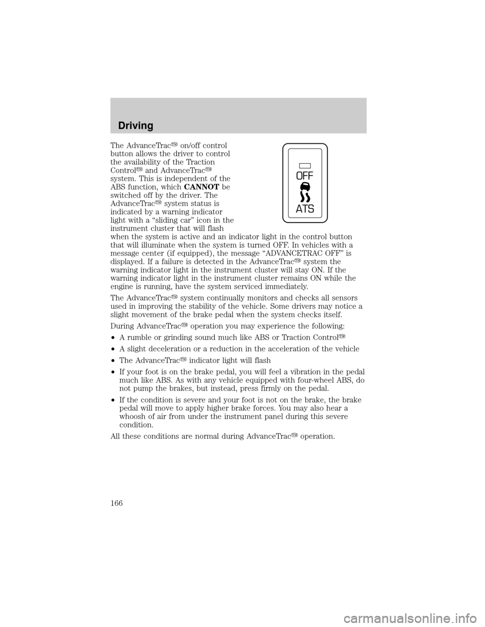
The AdvanceTracyon/off control
button allows the driver to control
the availability of the Traction
Controlyand AdvanceTracy
system. This is independent of the
ABS function, whichCANNOTbe
switched off by the driver. The
AdvanceTracysystem status is
indicated by a warning indicator
light with a ªsliding carº icon in the
instrument cluster that will flash
when the system is active and an indicator light in the control button
that will illuminate when the system is turned OFF. In vehicles with a
message center (if equipped), the message ªADVANCETRAC OFFº is
displayed. If a failure is detected in the AdvanceTracysystem the
warning indicator light in the instrument cluster will stay ON. If the
warning indicator light in the instrument cluster remains ON while the
engine is running, have the system serviced immediately.
The AdvanceTracysystem continually monitors and checks all sensors
used in improving the stability of the vehicle. Some drivers may notice a
slight movement of the brake pedal when the system checks itself.
During AdvanceTracyoperation you may experience the following:
²A rumble or grinding sound much like ABS or Traction Controly
²A slight deceleration or a reduction in the acceleration of the vehicle
²The AdvanceTracyindicator light will flash
²If your foot is on the brake pedal, you will feel a vibration in the pedal
much like ABS. As with any vehicle equipped with four-wheel ABS, do
not pump the brakes, but instead, press firmly on the pedal.
²If the condition is severe and your foot is not on the brake, the brake
pedal will move to apply higher brake forces. You may also hear a
whoosh of air from under the instrument panel during this severe
condition.
All these conditions are normal during AdvanceTracyoperation.
OFF
ATS
Driving
166
Page 169 of 288
When the battery is disconnected or a new battery installed, the
transmission must learn its adaptive strategy. As a result of this, the
transmission may shift firmly. This operation is considered normal and
will fully update transmission operation to its optimum shift feel.
Understanding gearshift positions
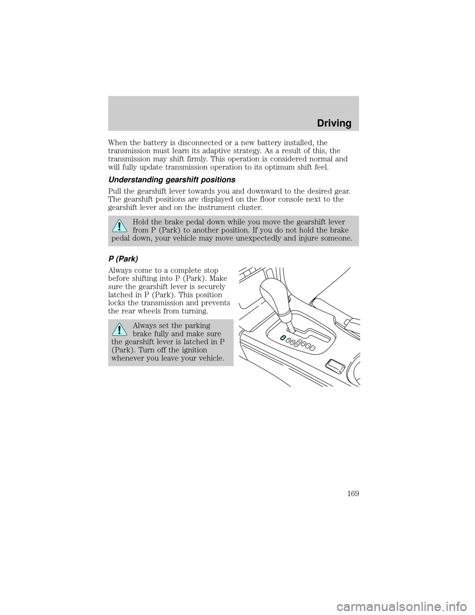
Pull the gearshift lever towards you and downward to the desired gear.
The gearshift positions are displayed on the floor console next to the
gearshift lever and on the instrument cluster.
Hold the brake pedal down while you move the gearshift lever
from P (Park) to another position. If you do not hold the brake
pedal down, your vehicle may move unexpectedly and injure someone.
P (Park)
Always come to a complete stop
before shifting into P (Park). Make
sure the gearshift lever is securely
latched in P (Park). This position
locks the transmission and prevents
the rear wheels from turning.
Always set the parking
brake fully and make sure
the gearshift lever is latched in P
(Park). Turn off the ignition
whenever you leave your vehicle.
PRND5D4321
Driving
169
Page 191 of 288
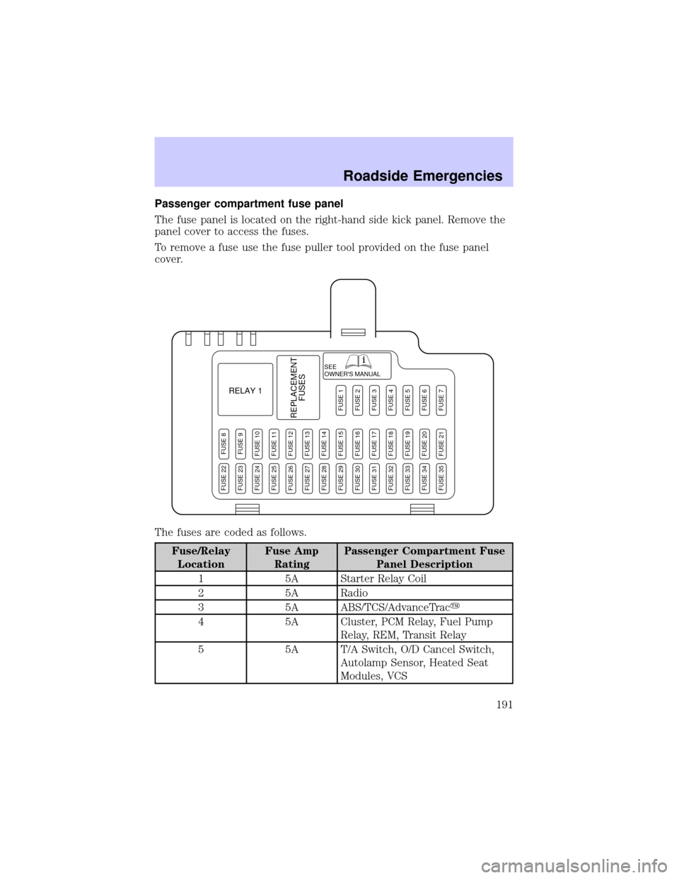
Passenger compartment fuse panel
The fuse panel is located on the right-hand side kick panel. Remove the
panel cover to access the fuses.
To remove a fuse use the fuse puller tool provided on the fuse panel
cover.
The fuses are coded as follows.
Fuse/Relay
LocationFuse Amp
RatingPassenger Compartment Fuse
Panel Description
1 5A Starter Relay Coil
2 5A Radio
3 5A ABS/TCS/AdvanceTracy
4 5A Cluster, PCM Relay, Fuel Pump
Relay, REM, Transit Relay
5 5A T/A Switch, O/D Cancel Switch,
Autolamp Sensor, Heated Seat
Modules, VCS
SEE
OWNER'S MANUAL
RELAY 1
REPLACEMENT
FUSES
FUSE 8FUSE 9FUSE 10FUSE 11FUSE 12FUSE 13FUSE 14FUSE 15FUSE 16FUSE 17FUSE 18FUSE 19FUSE 20FUSE 21
FUSE 1FUSE 2FUSE 3FUSE 4FUSE 5FUSE 6FUSE 7
FUSE 22FUSE 23FUSE 24FUSE 25FUSE 26FUSE 27FUSE 28FUSE 29FUSE 30FUSE 31FUSE 32FUSE 33FUSE 34FUSE 35
Roadside Emergencies
191
Page 192 of 288
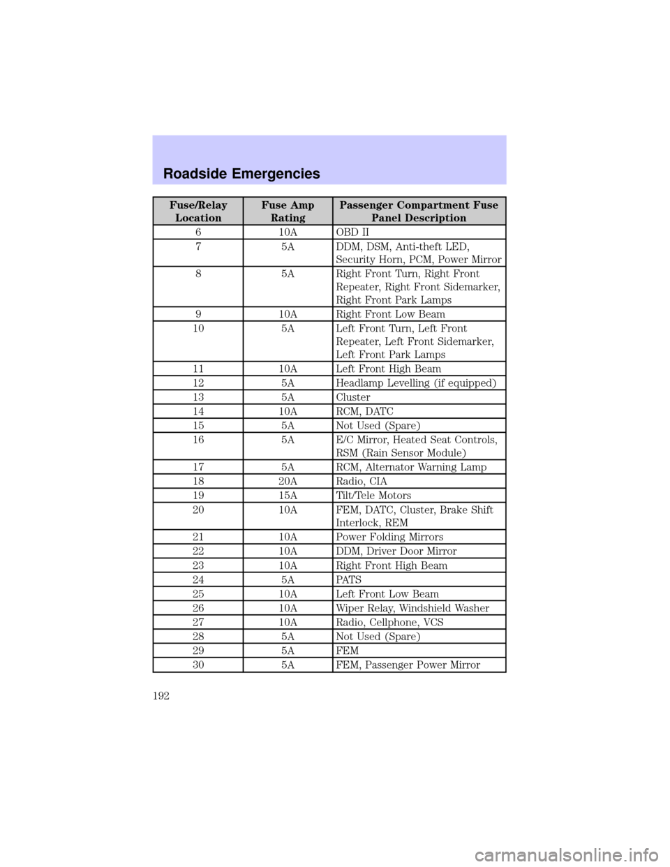
Fuse/Relay
LocationFuse Amp
RatingPassenger Compartment Fuse
Panel Description
6 10A OBD II
7 5A DDM, DSM, Anti-theft LED,
Security Horn, PCM, Power Mirror
8 5A Right Front Turn, Right Front
Repeater, Right Front Sidemarker,
Right Front Park Lamps
9 10A Right Front Low Beam
10 5A Left Front Turn, Left Front
Repeater, Left Front Sidemarker,
Left Front Park Lamps
11 10A Left Front High Beam
12 5A Headlamp Levelling (if equipped)
13 5A Cluster
14 10A RCM, DATC
15 5A Not Used (Spare)
16 5A E/C Mirror, Heated Seat Controls,
RSM (Rain Sensor Module)
17 5A RCM, Alternator Warning Lamp
18 20A Radio, CIA
19 15A Tilt/Tele Motors
20 10A FEM, DATC, Cluster, Brake Shift
Interlock, REM
21 10A Power Folding Mirrors
22 10A DDM, Driver Door Mirror
23 10A Right Front High Beam
24 5A PATS
25 10A Left Front Low Beam
26 10A Wiper Relay, Windshield Washer
27 10A Radio, Cellphone, VCS
28 5A Not Used (Spare)
29 5A FEM
30 5A FEM, Passenger Power Mirror
Roadside Emergencies
192