sensor LINCOLN LS 2003 User Guide
[x] Cancel search | Manufacturer: LINCOLN, Model Year: 2003, Model line: LS, Model: LINCOLN LS 2003Pages: 288, PDF Size: 3.19 MB
Page 160 of 288
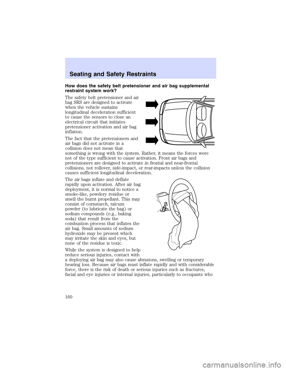
How does the safety belt pretensioner and air bag supplemental
restraint system work?
The safety belt pretensioner and air
bag SRS are designed to activate
when the vehicle sustains
longitudinal deceleration sufficient
to cause the sensors to close an
electrical circuit that initiates
pretensioner activation and air bag
inflation.
The fact that the pretensioners and
air bags did not activate in a
collision does not mean that
something is wrong with the system. Rather, it means the forces were
not of the type sufficient to cause activation. Front air bags and
pretensioners are designed to activate in frontal and near-frontal
collisions, not rollover, side-impact, or rear-impacts unless the collision
causes sufficient longitudinal deceleration.
The air bags inflate and deflate
rapidly upon activation. After air bag
deployment, it is normal to notice a
smoke-like, powdery residue or
smell the burnt propellant. This may
consist of cornstarch, talcum
powder (to lubricate the bag) or
sodium compounds (e.g., baking
soda) that result from the
combustion process that inflates the
air bag. Small amounts of sodium
hydroxide may be present which
may irritate the skin and eyes, but
none of the residue is toxic.
While the system is designed to help
reduce serious injuries, contact with
a deploying air bag may also cause abrasions, swelling or temporary
hearing loss. Because air bags must inflate rapidly and with considerable
force, there is the risk of death or serious injuries such as fractures,
facial and eye injuries or internal injuries, particularly to occupants who
Seating and Safety Restraints
160
Page 161 of 288
are not properly restrained or are otherwise out of position at the time
of air bag deployment. Thus, it is extremely important that occupants be
properly restrained as far away from the air bag module as possible while
maintaining vehicle control.
Several air bag system components get hot after inflation. Do not
touch them after inflation.
If the air bag has deployed,the air bag will not function
again and must be replaced immediately.If the air bag is not
replaced, the unrepaired area will increase the risk of injury in a
collision.
The SRS consists of:
•driver and passenger air bag modules (which include the inflators and
air bags)
•side air bags. Refer toSide air bag systemlater in this chapter
•safety belt pretensioners
•one or more impact and safing sensors
•a readiness light and tone
•and the electrical wiring which connects the components
The diagnostic module monitors its own internal circuits and the
supplemental air bag electrical system warning (including the impact
sensors), the system wiring, the air bag system readiness light, the air
bag back up power, the air bag ignitors and safety belt pretensioners.
Determining if the system is operational
The SRS uses a readiness light in the instrument cluster or a tone to
indicate the condition of the system. Refer to theAir bag readiness
section in theInstrument clusterchapter. Routine maintenance of the
air bag is not required.
Any difficulty with the system is indicated by one or more of the
following:
•The readiness light will either
flash or stay lit
•The readiness light will not
illuminate immediately after
ignition is turned to the RUN position
Seating and Safety Restraints
161
Page 163 of 288
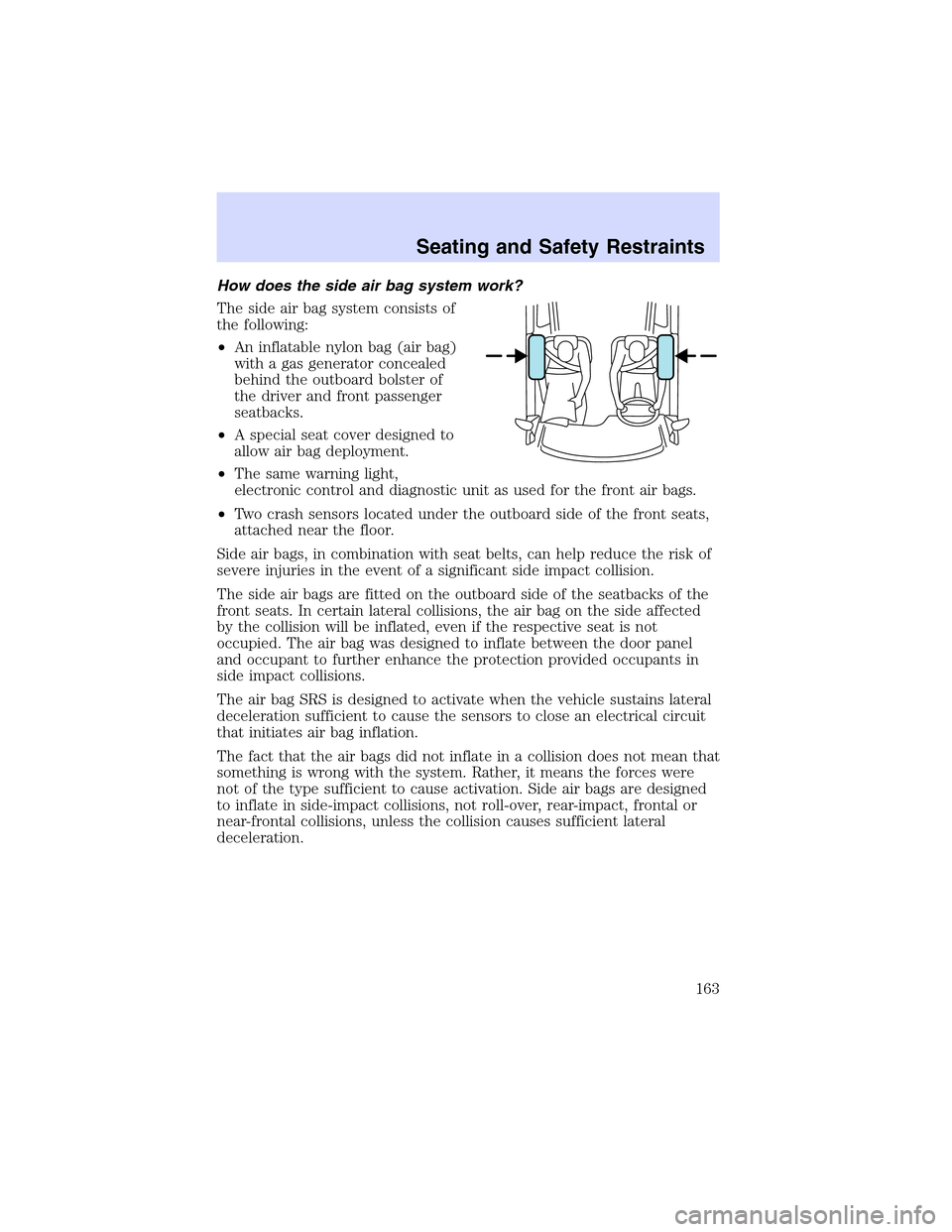
Howdoesthesideair bag system work?
The side air bag system consists of
the following:
•An inflatable nylon bag (air bag)
with a gas generator concealed
behind the outboard bolster of
the driver and front passenger
seatbacks.
•A special seat cover designed to
allow air bag deployment.
•The same warning light,
electronic control and diagnostic unit as used for the front air bags.
•Two crash sensors located under the outboard side of the front seats,
attached near the floor.
Side air bags, in combination with seat belts, can help reduce the risk of
severe injuries in the event of a significant side impact collision.
The side air bags are fitted on the outboard side of the seatbacks of the
front seats. In certain lateral collisions, the air bag on the side affected
by the collision will be inflated, even if the respective seat is not
occupied. The air bag was designed to inflate between the door panel
and occupant to further enhance the protection provided occupants in
side impact collisions.
The air bag SRS is designed to activate when the vehicle sustains lateral
deceleration sufficient to cause the sensors to close an electrical circuit
that initiates air bag inflation.
The fact that the air bags did not inflate in a collision does not mean that
something is wrong with the system. Rather, it means the forces were
not of the type sufficient to cause activation. Side air bags are designed
to inflate in side-impact collisions, not roll-over, rear-impact, frontal or
near-frontal collisions, unless the collision causes sufficient lateral
deceleration.
Seating and Safety Restraints
163
Page 167 of 288
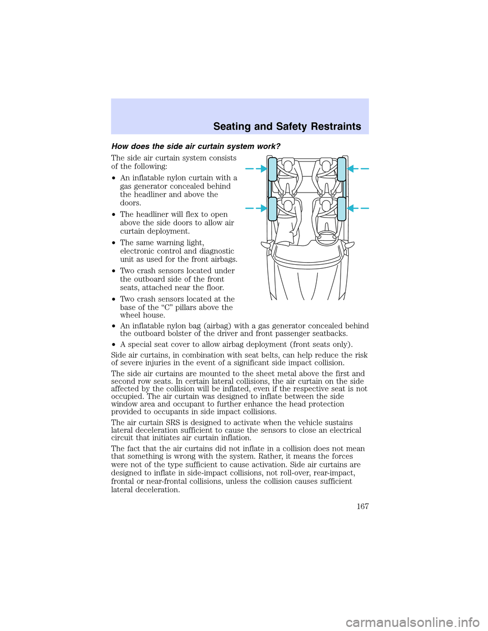
Howdoesthe side air curtain system work?
The side air curtain system consists
of the following:
•An inflatable nylon curtain with a
gas generator concealed behind
the headliner and above the
doors.
•The headliner will flex to open
above the side doors to allow air
curtain deployment.
•The same warning light,
electronic control and diagnostic
unit as used for the front airbags.
•Two crash sensors located under
the outboard side of the front
seats, attached near the floor.
•Two crash sensors located at the
base of the“C”pillars above the
wheel house.
•An inflatable nylon bag (airbag) with a gas generator concealed behind
the outboard bolster of the driver and front passenger seatbacks.
•A special seat cover to allow airbag deployment (front seats only).
Side air curtains, in combination with seat belts, can help reduce the risk
of severe injuries in the event of a significant side impact collision.
The side air curtains are mounted to the sheet metal above the first and
second row seats. In certain lateral collisions, the air curtain on the side
affected by the collision will be inflated, even if the respective seat is not
occupied. The air curtain was designed to inflate between the side
window area and occupant to further enhance the head protection
provided to occupants in side impact collisions.
The air curtain SRS is designed to activate when the vehicle sustains
lateral deceleration sufficient to cause the sensors to close an electrical
circuit that initiates air curtain inflation.
The fact that the air curtains did not inflate in a collision does not mean
that something is wrong with the system. Rather, it means the forces
were not of the type sufficient to cause activation. Side air curtains are
designed to inflate in side-impact collisions, not roll-over, rear-impact,
frontal or near-frontal collisions, unless the collision causes sufficient
lateral deceleration.
Seating and Safety Restraints
167
Page 197 of 288
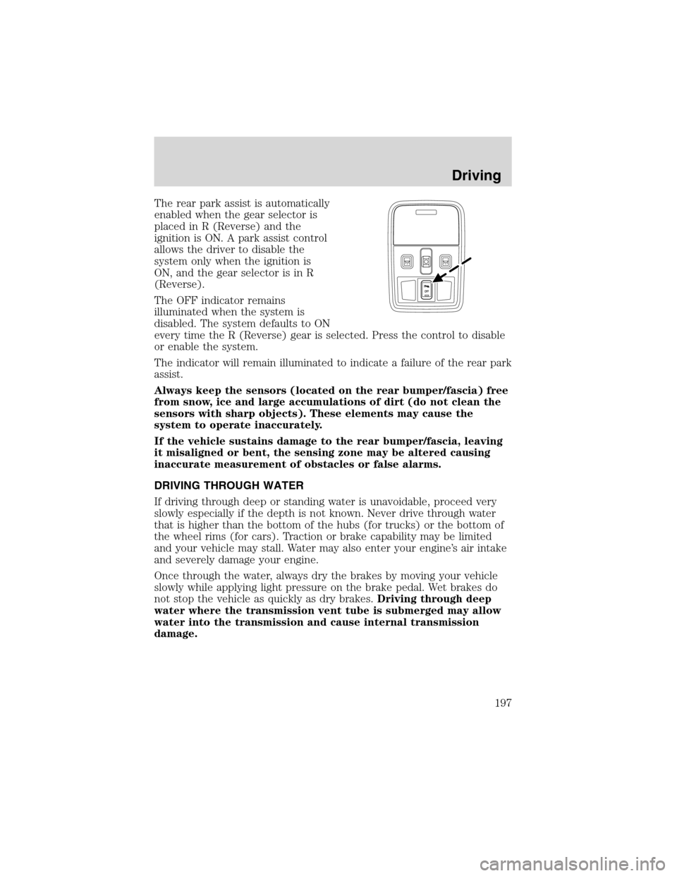
Therearpark assist is automatically
enabled when the gear selector is
placed in R (Reverse) and the
ignition is ON. A park assist control
allows the driver to disable the
system only when the ignition is
ON, and the gear selector is in R
(Reverse).
The OFF indicator remains
illuminated when the system is
disabled. The system defaults to ON
every time the R (Reverse) gear is selected. Press the control to disable
or enable the system.
The indicator will remain illuminated to indicate a failure of the rear park
assist.
Always keep the sensors (located on the rear bumper/fascia) free
from snow, ice and large accumulations of dirt (do not clean the
sensors with sharp objects). These elements may cause the
system to operate inaccurately.
If the vehicle sustains damage to the rear bumper/fascia, leaving
it misaligned or bent, the sensing zone may be altered causing
inaccurate measurement of obstacles or false alarms.
DRIVING THROUGH WATER
If driving through deep or standing water is unavoidable, proceed very
slowly especially if the depth is not known. Never drive through water
that is higher than the bottom of the hubs (for trucks) or the bottom of
the wheel rims (for cars). Traction or brake capability may be limited
and your vehicle may stall. Water may also enter your engine’s air intake
and severely damage your engine.
Once through the water, always dry the brakes by moving your vehicle
slowly while applying light pressure on the brake pedal. Wet brakes do
not stop the vehicle as quickly as dry brakes.Driving through deep
water where the transmission vent tube is submerged may allow
water into the transmission and cause internal transmission
damage.
Driving
197
Page 205 of 288
Fuse/Relay
LocationFuse Amp
RatingPassenger Compartment Fuse
Panel Description
7 5A DDM, DSM, Anti-theft LED,
Power mirror switch, Electric
Park Brake (EPB) switch
8 5A Right front turn, Right front
repeater, Right front sidemarker,
Right front park lamps
9 15A Right front low beam/HID
10 5A Left front turn, Left front
repeater, Left front sidemarker,
Left front park lamps
11 10A Left front high beam
12 5A Rain sensor, Electrochromic
mirror
13 5A Cluster
14 5A DATC
15 5A O/D cancel, ABS/Traction-Assist
switch
16 5A Heated seat controls, Climate
control seat module
17 5A RCM, Alternator warning lamp
18 20A Radio, CIA, Navigation unit
19 15A Tilt/Tele motors
20 10A FEM, DATC, Cluster, REM
21 7.5A Not used (spare)
22 10A DDM, Driver door mirror
23 10A Right front high beam
24 5A PATS
25 15A Left front low beam/HID
26 5A Wiper module
27 10A Radio, Navigation unit
28 5A Not Used (spare)
29 5A FEM, Reverse park assist
Roadside Emergencies
205
Page 207 of 288
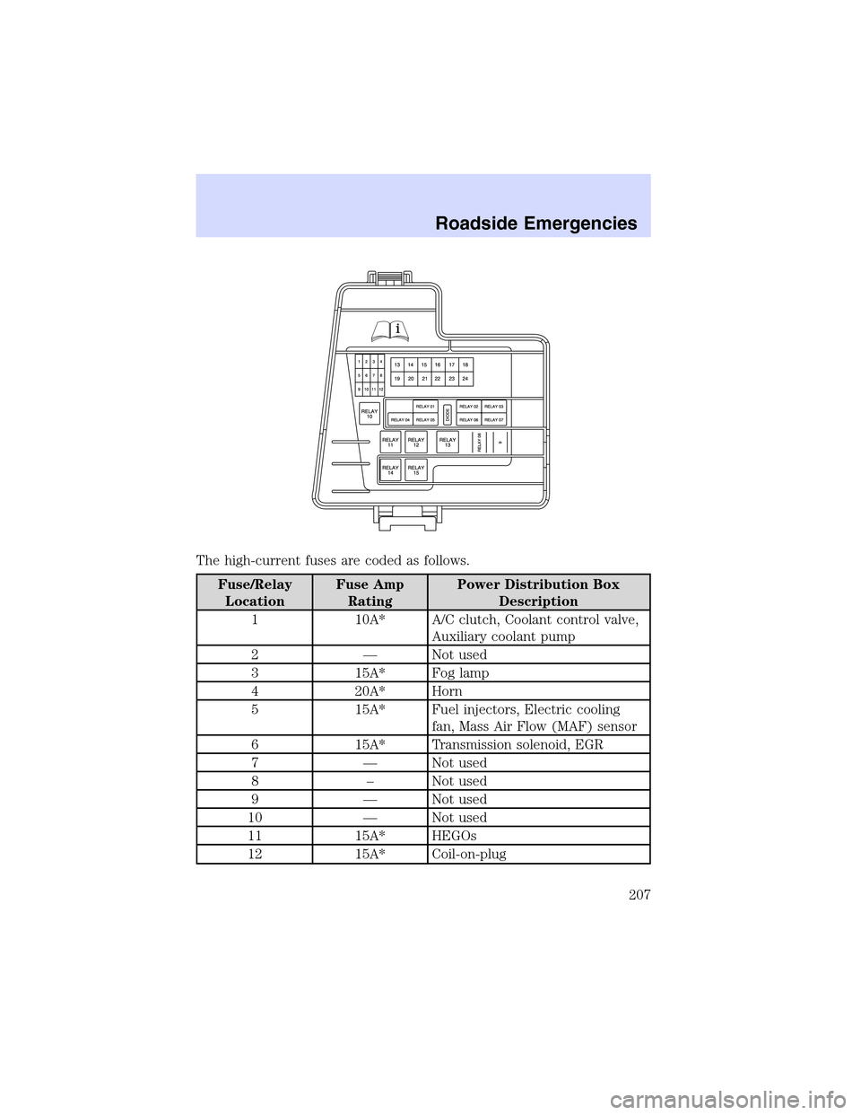
The high-current fuses are coded as follows.
Fuse/Relay
LocationFuse Amp
RatingPower Distribution Box
Description
1 10A* A/C clutch, Coolant control valve,
Auxiliary coolant pump
2—Not used
3 15A* Fog lamp
4 20A* Horn
5 15A* Fuel injectors, Electric cooling
fan, Mass Air Flow (MAF) sensor
6 15A* Transmission solenoid, EGR
7—Not used
8–Not used
9—Not used
10—Not used
11 15A* HEGOs
12 15A* Coil-on-plug
Roadside Emergencies
207
Page 285 of 288
Passenger Occupant
Classification Sensor .................143
Pedals (see Power
adjustable foot pedals) ...............95
Power adjustable foot pedals .....95
Power distribution box
(see Fuses) .......................206, 209
Power door locks ......................120
Power steering ..........................186
fluid, checking and adding ....263
fluid, refill capacity ................272
fluid, specifications .........274–275
Power Windows ...........................90
R
Radio ......................................16, 20
Rear Park Assist .......................195
Rear window defroster ...............76
Relays ........................................202
Remote entry system ...............124
opening the trunk ...................125
Roadside assistance ..................200
Roof rack ...................................119
S
Safety Belt Maintenance ..........156
Safety belts (see Safety
restraints) ..........142, 145, 147–151
Safety defects, reporting ..........232
Safety restraints ...............142, 145,
147–151
belt minder .............................152
extension assembly ................156
for adults .........................147–150
for children .............................169Occupant Classification
Sensor ......................................143
safety belt maintenance .........156
warning light and
chime ...............................151–152
Safety seats for children ..........172
Seat belts (see
Safety restraints) ......................142
Seats ..........................................135
child safety seats ....................172
cleaning ...................................236
climate control ........................138
easy access/easyout
feature .....................................137
memory seat ...................128, 138
Select Shift Transmission
(SST) shifter .............................193
Servicing your vehicle ..............239
Spare tire (see
Changing the Tire) ...................212
Spark plugs,
specifications .............271, 275–276
Specification chart,
lubricants ...........................274–275
Speed control ..............................95
Starting your vehicle ........181–183
jump starting ..........................216
Steering
speed sensitive .......................186
Steering column lock ..................89
Steering wheel
controls ......................................98
tilting .........................................88
T
Tires ...........................211, 266–268
changing ..........................211–213
Index
285