LINCOLN MARK LT 2008 Owners Manual
Manufacturer: LINCOLN, Model Year: 2008, Model line: MARK LT, Model: LINCOLN MARK LT 2008Pages: 328, PDF Size: 3.17 MB
Page 111 of 328
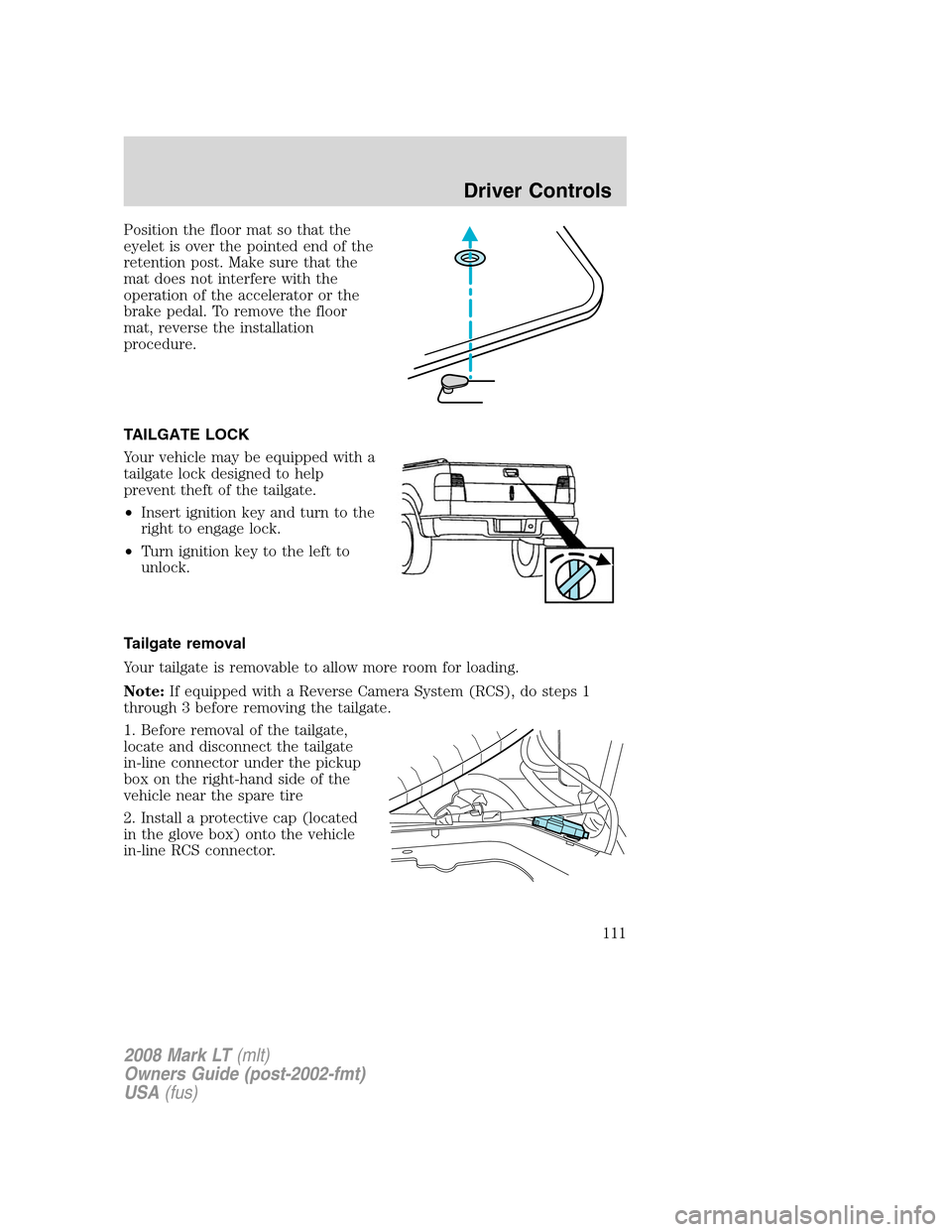
Position the floor mat so that the
eyelet is over the pointed end of the
retention post. Make sure that the
mat does not interfere with the
operation of the accelerator or the
brake pedal. To remove the floor
mat, reverse the installation
procedure.
TAILGATE LOCK
Your vehicle may be equipped with a
tailgate lock designed to help
prevent theft of the tailgate.
•Insert ignition key and turn to the
right to engage lock.
•Turn ignition key to the left to
unlock.
Tailgate removal
Your tailgate is removable to allow more room for loading.
Note:If equipped with a Reverse Camera System (RCS), do steps 1
through 3 before removing the tailgate.
1. Before removal of the tailgate,
locate and disconnect the tailgate
in-line connector under the pickup
box on the right-hand side of the
vehicle near the spare tire
2. Install a protective cap (located
in the glove box) onto the vehicle
in-line RCS connector.
2008 Mark LT(mlt)
Owners Guide (post-2002-fmt)
USA(fus)
Driver Controls
111
Page 112 of 328
3. Partially lower tailgate and carefully feed tailgate harness up through
the truck box and the bumper. Secure the tailgate harness onto the
vehicle box.
4. Lower the tailgate.
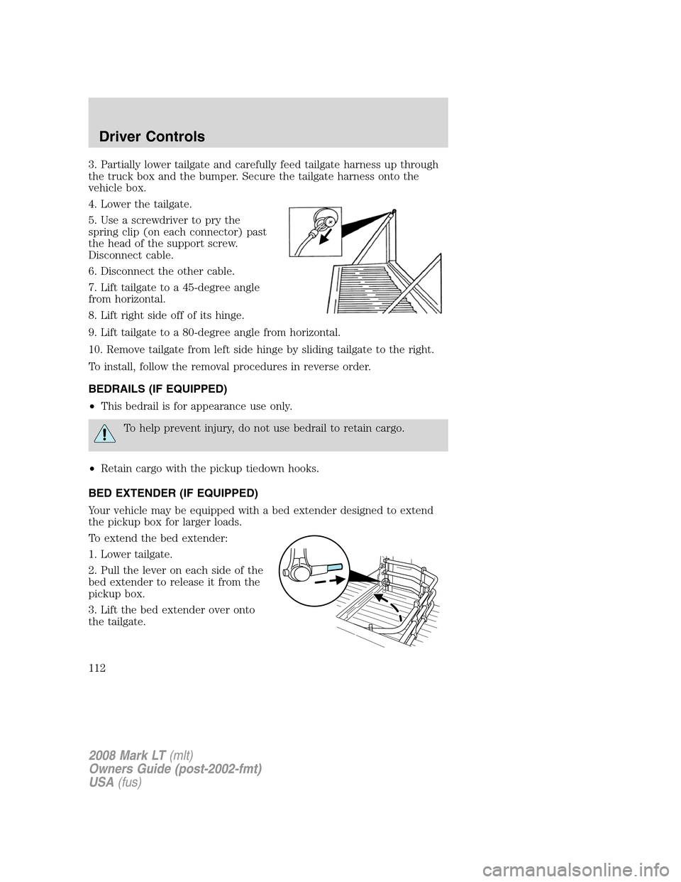
5. Use a screwdriver to pry the
spring clip (on each connector) past
the head of the support screw.
Disconnect cable.
6. Disconnect the other cable.
7. Lift tailgate to a 45-degree angle
from horizontal.
8. Lift right side off of its hinge.
9. Lift tailgate to a 80-degree angle from horizontal.
10. Remove tailgate from left side hinge by sliding tailgate to the right.
To install, follow the removal procedures in reverse order.
BEDRAILS (IF EQUIPPED)
•This bedrail is for appearance use only.
To help prevent injury, do not use bedrail to retain cargo.
•Retain cargo with the pickup tiedown hooks.
BED EXTENDER (IF EQUIPPED)
Your vehicle may be equipped with a bed extender designed to extend
the pickup box for larger loads.
To extend the bed extender:
1. Lower tailgate.
2. Pull the lever on each side of the
bed extender to release it from the
pickup box.
3. Lift the bed extender over onto
the tailgate.
2008 Mark LT(mlt)
Owners Guide (post-2002-fmt)
USA(fus)
Driver Controls
112
Page 113 of 328
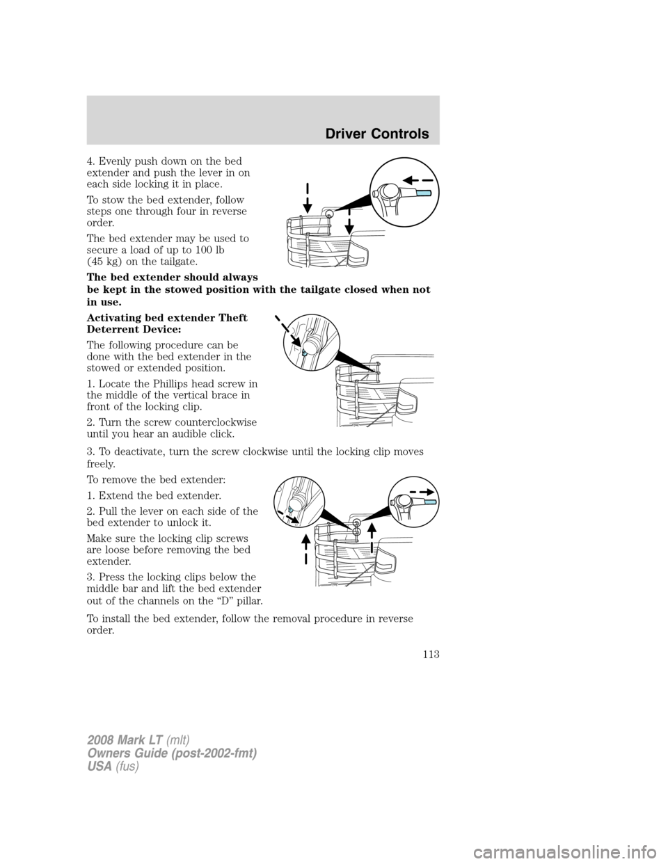
4. Evenly push down on the bed
extender and push the lever in on
each side locking it in place.
To stow the bed extender, follow
steps one through four in reverse
order.
The bed extender may be used to
secure a load of up to 100 lb
(45 kg) on the tailgate.
The bed extender should always
be kept in the stowed position with the tailgate closed when not
in use.
Activating bed extender Theft
Deterrent Device:
The following procedure can be
done with the bed extender in the
stowed or extended position.
1. Locate the Phillips head screw in
the middle of the vertical brace in
front of the locking clip.
2. Turn the screw counterclockwise
until you hear an audible click.
3. To deactivate, turn the screw clockwise until the locking clip moves
freely.
To remove the bed extender:
1. Extend the bed extender.
2. Pull the lever on each side of the
bed extender to unlock it.
Make sure the locking clip screws
are loose before removing the bed
extender.
3. Press the locking clips below the
middle bar and lift the bed extender
out of the channels on the “D” pillar.
To install the bed extender, follow the removal procedure in reverse
order.
2008 Mark LT(mlt)
Owners Guide (post-2002-fmt)
USA(fus)
Driver Controls
113
Page 114 of 328
CARGO AREA FEATURES (IF EQUIPPED)
Cargo management system (if equipped)
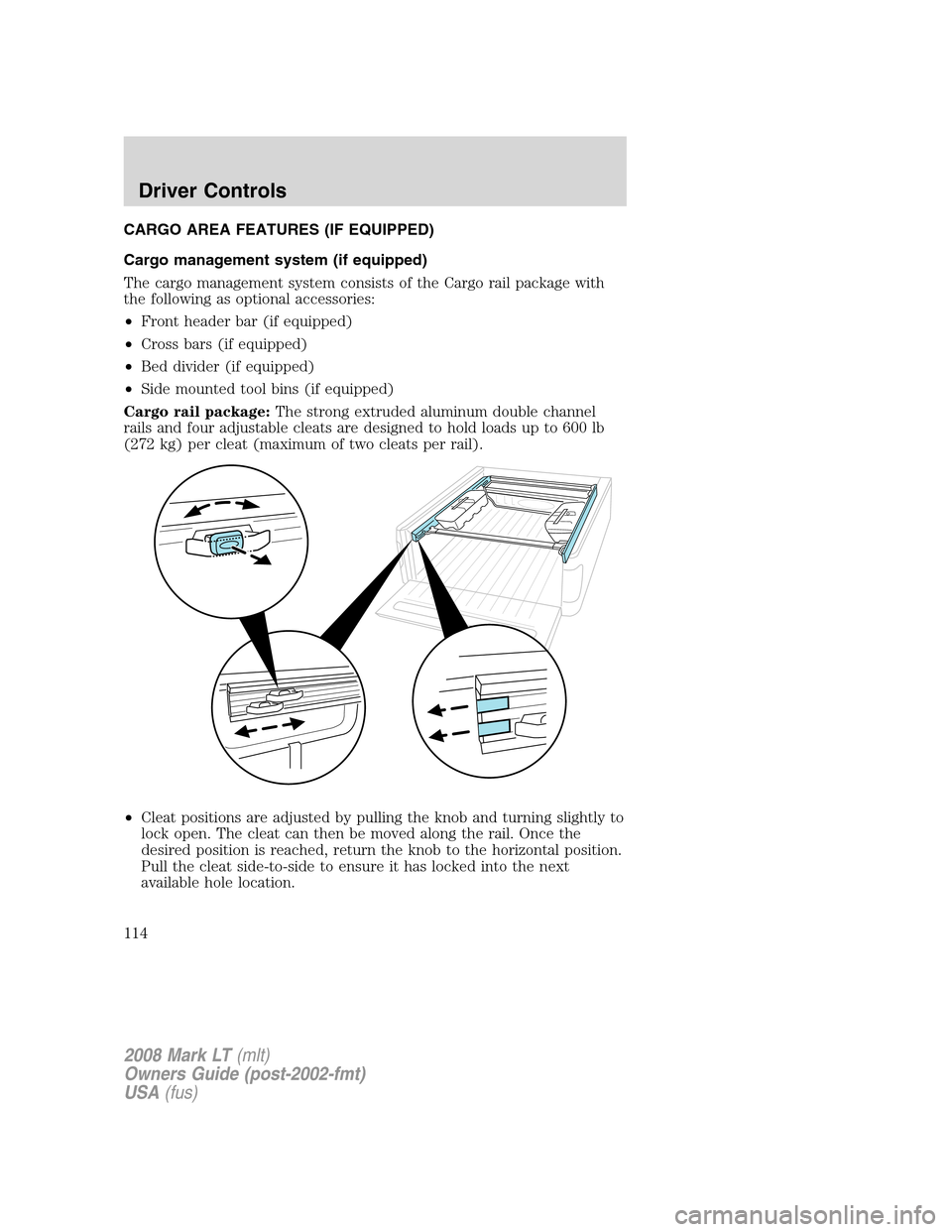
The cargo management system consists of the Cargo rail package with
the following as optional accessories:
•Front header bar (if equipped)
•Cross bars (if equipped)
•Bed divider (if equipped)
•Side mounted tool bins (if equipped)
Cargo rail package:The strong extruded aluminum double channel
rails and four adjustable cleats are designed to hold loads up to 600 lb
(272 kg) per cleat (maximum of two cleats per rail).
•Cleat positions are adjusted by pulling the knob and turning slightly to
lock open. The cleat can then be moved along the rail. Once the
desired position is reached, return the knob to the horizontal position.
Pull the cleat side-to-side to ensure it has locked into the next
available hole location.
2008 Mark LT(mlt)
Owners Guide (post-2002-fmt)
USA(fus)
Driver Controls
114
Page 115 of 328
•To remove cleat from rail, release rail endcap by pulling inboard and
towards the end of the rail on the two plastic tabs located inside the
tracks at each end of the rails. The plastic endcap will then release
and may be removed. The cleat can then be slid out the end of the
rail.
When installing cleat, reverse instructions above.
Note:When replacing a cleat into the rail, make sure the oval embossed
on the knob is not upside down. This will ensure that the cleat is
properly oriented to accept accessory attachments.
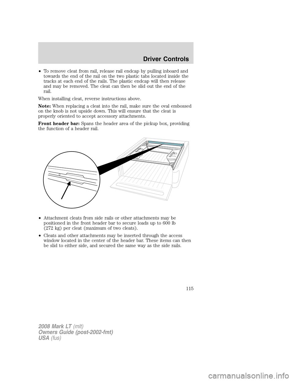
Front header bar:Spans the header area of the pickup box, providing
the function of a header rail.
•Attachment cleats from side rails or other attachments may be
positioned in the front header bar to secure loads up to 600 lb
(272 kg) per cleat (maximum of two cleats).
•Cleats and other attachments may be inserted through the access
window located in the center of the header bar. These items can then
be slid to either side, and secured the same way as the side rails.
2008 Mark LT(mlt)
Owners Guide (post-2002-fmt)
USA(fus)
Driver Controls
115
Page 116 of 328
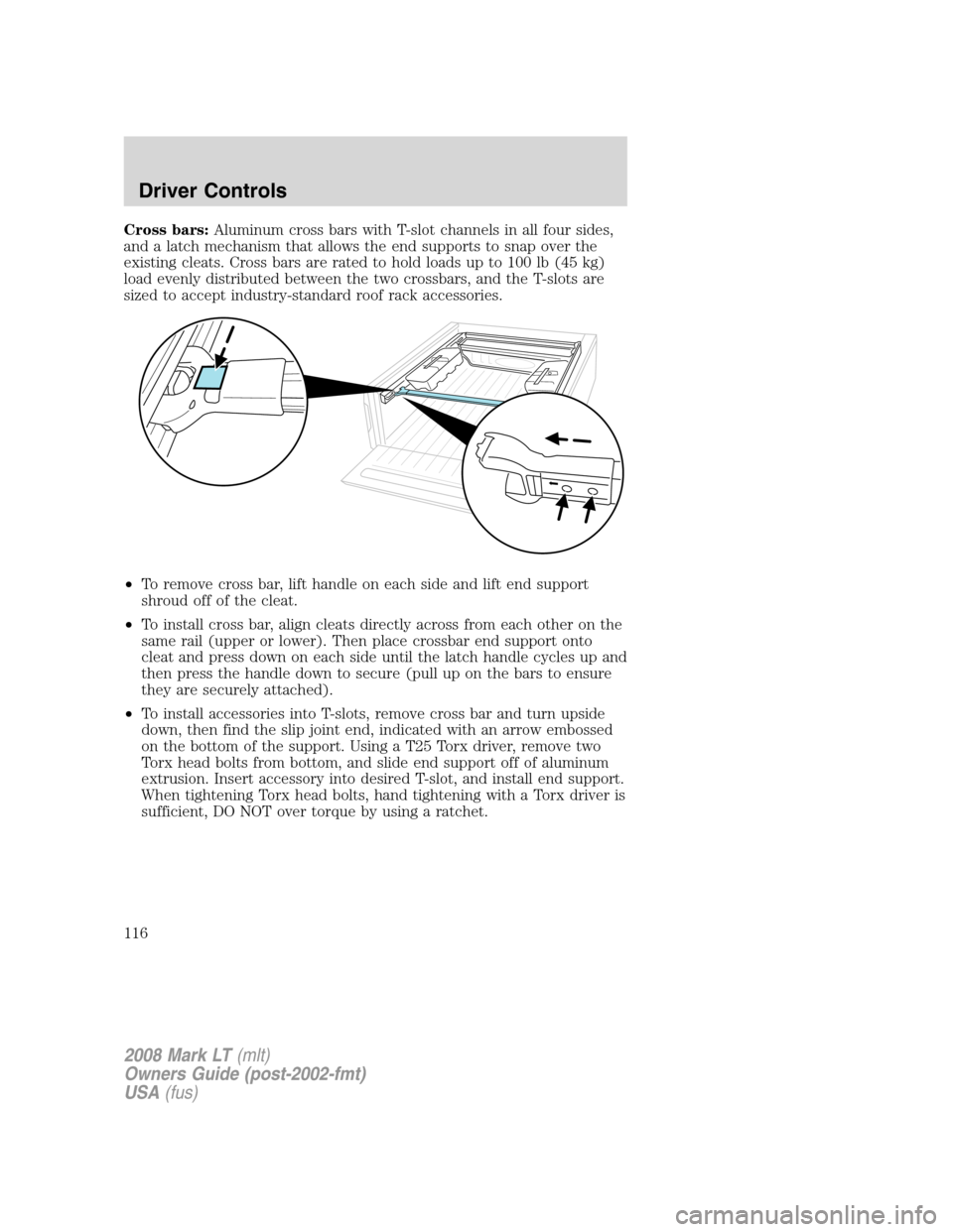
Cross bars:Aluminum cross bars with T-slot channels in all four sides,
and a latch mechanism that allows the end supports to snap over the
existing cleats. Cross bars are rated to hold loads up to 100 lb (45 kg)
load evenly distributed between the two crossbars, and the T-slots are
sized to accept industry-standard roof rack accessories.
•To remove cross bar, lift handle on each side and lift end support
shroud off of the cleat.
•To install cross bar, align cleats directly across from each other on the
same rail (upper or lower). Then place crossbar end support onto
cleat and press down on each side until the latch handle cycles up and
then press the handle down to secure (pull up on the bars to ensure
they are securely attached).
•To install accessories into T-slots, remove cross bar and turn upside
down, then find the slip joint end, indicated with an arrow embossed
on the bottom of the support. Using a T25 Torx driver, remove two
Torx head bolts from bottom, and slide end support off of aluminum
extrusion. Insert accessory into desired T-slot, and install end support.
When tightening Torx head bolts, hand tightening with a Torx driver is
sufficient, DO NOT over torque by using a ratchet.
2008 Mark LT(mlt)
Owners Guide (post-2002-fmt)
USA(fus)
Driver Controls
116
Page 117 of 328
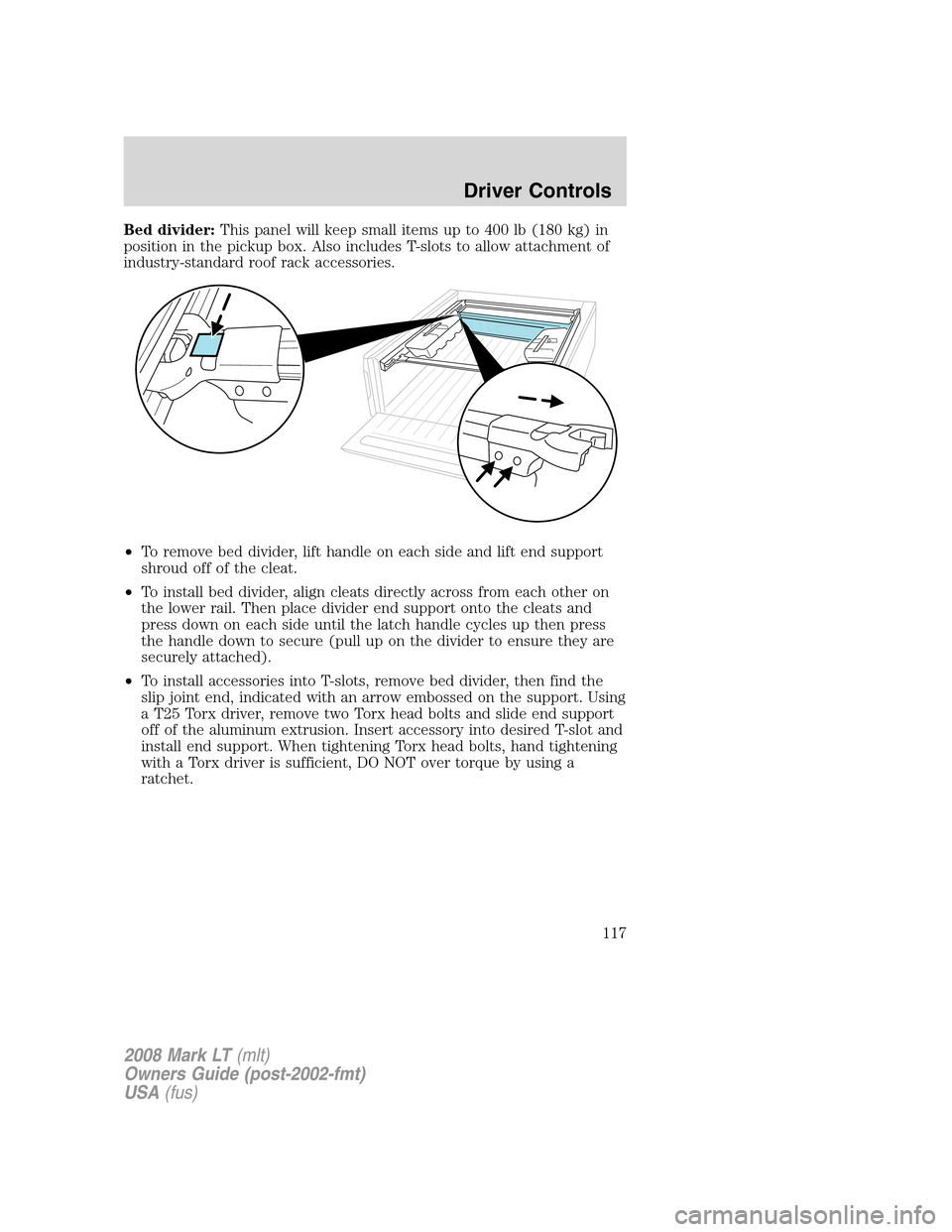
Bed divider:This panel will keep small items up to 400 lb (180 kg) in
position in the pickup box. Also includes T-slots to allow attachment of
industry-standard roof rack accessories.
•To remove bed divider, lift handle on each side and lift end support
shroud off of the cleat.
•To install bed divider, align cleats directly across from each other on
the lower rail. Then place divider end support onto the cleats and
press down on each side until the latch handle cycles up then press
the handle down to secure (pull up on the divider to ensure they are
securely attached).
•To install accessories into T-slots, remove bed divider, then find the
slip joint end, indicated with an arrow embossed on the support. Using
a T25 Torx driver, remove two Torx head bolts and slide end support
off of the aluminum extrusion. Insert accessory into desired T-slot and
install end support. When tightening Torx head bolts, hand tightening
with a Torx driver is sufficient, DO NOT over torque by using a
ratchet.
2008 Mark LT(mlt)
Owners Guide (post-2002-fmt)
USA(fus)
Driver Controls
117
Page 118 of 328
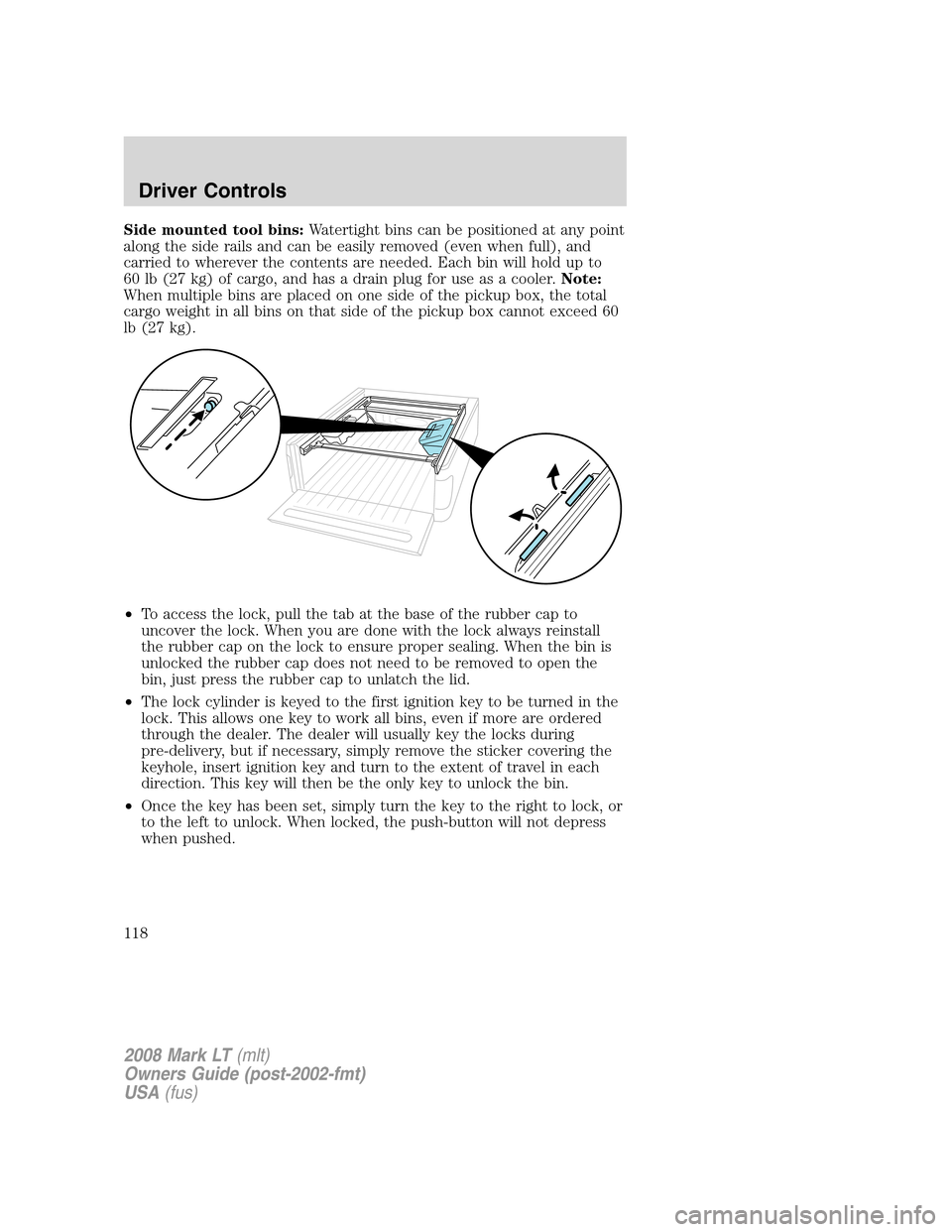
Side mounted tool bins:Watertight bins can be positioned at any point
along the side rails and can be easily removed (even when full), and
carried to wherever the contents are needed. Each bin will hold up to
60 lb (27 kg) of cargo, and has a drain plug for use as a cooler.Note:
When multiple bins are placed on one side of the pickup box, the total
cargo weight in all bins on that side of the pickup box cannot exceed 60
lb (27 kg).
•To access the lock, pull the tab at the base of the rubber cap to
uncover the lock. When you are done with the lock always reinstall
the rubber cap on the lock to ensure proper sealing. When the bin is
unlocked the rubber cap does not need to be removed to open the
bin, just press the rubber cap to unlatch the lid.
•The lock cylinder is keyed to the first ignition key to be turned in the
lock. This allows one key to work all bins, even if more are ordered
through the dealer. The dealer will usually key the locks during
pre-delivery, but if necessary, simply remove the sticker covering the
keyhole, insert ignition key and turn to the extent of travel in each
direction. This key will then be the only key to unlock the bin.
•Once the key has been set, simply turn the key to the right to lock, or
to the left to unlock. When locked, the push-button will not depress
when pushed.
2008 Mark LT(mlt)
Owners Guide (post-2002-fmt)
USA(fus)
Driver Controls
118
Page 119 of 328
•To remove the bin from the rail, open lid and pull up on both levers
located on the outboard edge (next to the pickup box top rail) until
the handles are all the way up (approximately 90 degrees). Once both
handles are raised, the lid may be closed.Note:Windows in the lid
will allow the handles to stick up above the lid (with the lid closed).
After closing the lid, simply lift up and inboard away from the pickup
box side to release bin from rail.
•To install, reverse the above instructions.
Note:Remove the bins during severe off road driving to avoid damage to
the cargo bins and pickup box.
If any levers are visible above the lid of the bin, the bin is not
securely attached to the rail, and may become detached from the
vehicle if driven in that configuration.
2008 Mark LT(mlt)
Owners Guide (post-2002-fmt)
USA(fus)
Driver Controls
119
Page 120 of 328
KEYS
The key operates all locks on your vehicle. In case of loss, replacement
keys are available from your dealer.
You should always carry a second key with you in a safe place in case
you require it in an emergency.
Refer to theSecuriLock™ passive anti-theft systemsection in this
chapter for more information.
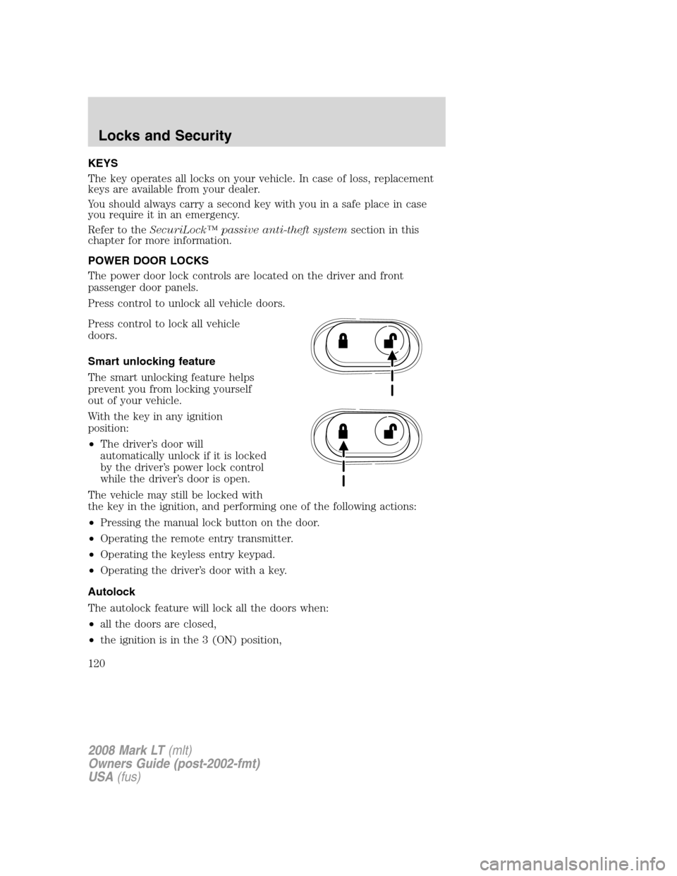
POWER DOOR LOCKS
The power door lock controls are located on the driver and front
passenger door panels.
Press control to unlock all vehicle doors.
Press control to lock all vehicle
doors.
Smart unlocking feature
The smart unlocking feature helps
prevent you from locking yourself
out of your vehicle.
With the key in any ignition
position:
•The driver’s door will
automatically unlock if it is locked
by the driver’s power lock control
while the driver’s door is open.
The vehicle may still be locked with
the key in the ignition, and performing one of the following actions:
•Pressing the manual lock button on the door.
•Operating the remote entry transmitter.
•Operating the keyless entry keypad.
•Operating the driver’s door with a key.
Autolock
The autolock feature will lock all the doors when:
•all the doors are closed,
•the ignition is in the 3 (ON) position,
2008 Mark LT(mlt)
Owners Guide (post-2002-fmt)
USA(fus)
Locks and Security
120