ESP LINCOLN MKC 2015 Owners Manual
[x] Cancel search | Manufacturer: LINCOLN, Model Year: 2015, Model line: MKC, Model: LINCOLN MKC 2015Pages: 490, PDF Size: 4.74 MB
Page 8 of 490
Cleaning the Interior...................................302
Cleaning the Instrument Panel and
Instrument Cluster Lens.........................303
Cleaning Leather Seats..............................304
Repairing Minor Paint Damage.................305
Cleaning the Alloy Wheels........................305
Vehicle Storage
............................................305
Wheels and Tires
General Information
.....................................308
Tire Care
..........................................................310
Using Snow Chains......................................323
Tire Pressure Monitoring System.............324
Changing a Road Wheel............................328
Technical Specifications.............................334
Capacities and Specifications
Engine Specifications
..................................336
Motorcraft Parts.............................................337
Vehicle Identification Number
..................339
Vehicle Certification Label
.........................339
Transmission Code Designation..............340
Technical Specifications..............................341 Audio System
General Information.....................................345
Audio unit -
Vehicles With: Premium AM/
FM/CD.........................................................346
Media Hub
......................................................348
MyLincoln Touch ™
General Information
.....................................350
Settings...........................................................363
Entertainment................................................376
Phone..............................................................396
Information.....................................................403
Climate.............................................................414
Navigation.......................................................418
Accessories
Accessories...................................................428
Appendices
End User License Agreement
...................430
Extended Service Plan (ESP)
Extended Service Plan (ESP).....................448 Scheduled Maintenance
General Maintenance Information............451
Normal Scheduled Maintenance
.............455
Special Operating Conditions Scheduled Maintenance.............................................459
Scheduled Maintenance Record
..............463
5
MKC (TME), enUSA Table of Contents
Page 10 of 490
ABOUT THIS MANUAL
Thank you for choosing Lincoln. We
recommend that you take some time to get
to know your vehicle by reading this manual.
The more that you know about it, the greater
the safety and pleasure you will get from
driving it.
WARNING
Driving while distracted can result in
loss of vehicle control, crash and injury.
We strongly recommend that you use
extreme caution when using any device that
may take your focus off the road. Your
primary responsibility is the safe operation
of your vehicle. We recommend against the
use of any handheld device while driving and
encourage the use of voice-operated
systems when possible. Make sure you are
aware of all applicable local laws that may
affect the use of electronic devices while
driving. Note:
This manual describes product
features and options available throughout
the range of available models, sometimes
even before they are generally available. It
may describe options not fitted to your
vehicle.
Note: Some of the illustrations in this manual
may be used for different models, so may
appear different to you on your vehicle.
However, the essential information in the
illustrations is always correct.
Note: Always use and operate your vehicle
in line with all applicable laws and
regulations.
Note: Pass on this manual when selling your
vehicle. It is an integral part of the vehicle.
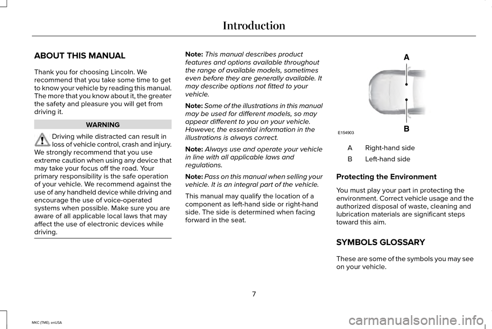
This manual may qualify the location of a
component as left-hand side or right-hand
side. The side is determined when facing
forward in the seat. Right-hand side
A
Left-hand side
B
Protecting the Environment
You must play your part in protecting the
environment. Correct vehicle usage and the
authorized disposal of waste, cleaning and
lubrication materials are significant steps
toward this aim.
SYMBOLS GLOSSARY
These are some of the symbols you may see
on your vehicle.
7
MKC (TME), enUSA IntroductionE154903
Page 17 of 490
WARNING
Driving while distracted can result in
loss of vehicle control, crash and injury.
We strongly recommend that you use
extreme caution when using any device that
may take your focus off the road. Your
primary responsibility is the safe operation
of your vehicle. We recommend against the
use of any hand-held device while driving
and encourage the use of voice-operated
systems when possible. Make sure you are
aware of all applicable local laws that may
affect the use of electronic devices while
driving. EXPORT UNIQUE OPTIONS
For your particular global region, your vehicle
may be equipped with features and options
that are different from the features and
options that are described in this Owner’
s
Manual. A market unique supplement may
be supplied that complements this book. By
referring to the market unique supplement,
if provided, you can properly identify those
features, recommendations and
specifications that are unique to your vehicle. This Owner’
s Manual is written primarily for
the U.S. and Canadian Markets. Features or
equipment listed as standard may be
different on units built for Export. Refer to
this Owner’ s Manual for all other required
information and warnings.
14
MKC (TME), enUSA Introduction
Page 26 of 490
GENERAL INFORMATION
See the following sections for directions on
how to properly use safety restraints for
children.
WARNINGS
Always make sure your child is secured
properly in a device that is appropriate
for their height, age and weight. Child safety
restraints must be bought separately from
your vehicle. Failure to follow these
instructions and guidelines may result in an
increased risk of serious injury or death to
your child. WARNINGS
All children are shaped differently. The
recommendations for safety restraints
are based on probable child height, age and
weight thresholds from National Highway
Traffic Safety Administration and other safety
organizations, or are the minimum
requirements of law. Ford recommends
checking with a NHTSA Certified Child
Passenger Safety Technician (CPST) and
consult your pediatrician to make sure your
child seat is appropriate for your child, and
is compatible with and properly installed in
your vehicle. To locate a child seat fitting
station and CPST, contact the NHTSA toll WARNINGS
free at 1-888-327-4236 or go to
http://www.nhtsa.dot.gov. In Canada, check
with your local St. John Ambulance office for
referral to a CPST or for further information,
contact your provincial ministry of
transportation, locate your local St. John
Ambulance office by searching for St. John
Ambulance on the internet, or Transport
Canada at 1-800-333-0371
(http://www.tc.gc.ca). Failure to properly
restrain children in safety seats made
especially for their height, age, and weight
may result in an increased risk of serious
injury or death to your child. 23
MKC (TME), enUSA Child Safety
Page 42 of 490
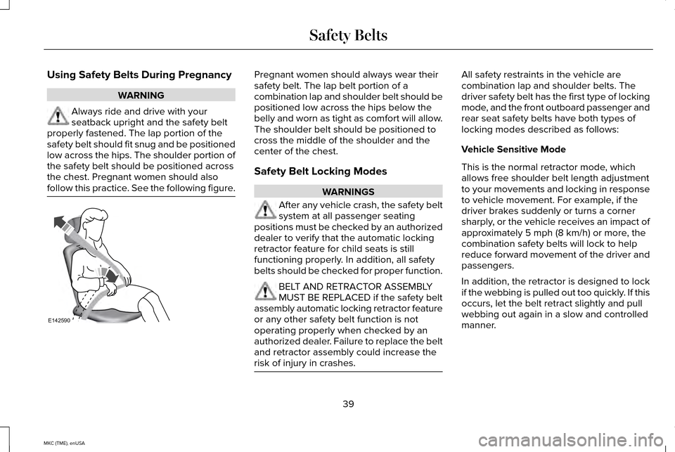
Using Safety Belts During Pregnancy
WARNING
Always ride and drive with your
seatback upright and the safety belt
properly fastened. The lap portion of the
safety belt should fit snug and be positioned
low across the hips. The shoulder portion of
the safety belt should be positioned across
the chest. Pregnant women should also
follow this practice. See the following figure. Pregnant women should always wear their
safety belt. The lap belt portion of a
combination lap and shoulder belt should be
positioned low across the hips below the
belly and worn as tight as comfort will allow.
The shoulder belt should be positioned to
cross the middle of the shoulder and the
center of the chest.
Safety Belt Locking Modes
WARNINGS
After any vehicle crash, the safety belt
system at all passenger seating
positions must be checked by an authorized
dealer to verify that the automatic locking
retractor feature for child seats is still
functioning properly. In addition, all safety
belts should be checked for proper function. BELT AND RETRACTOR ASSEMBLY
MUST BE REPLACED if the safety belt
assembly automatic locking retractor feature
or any other safety belt function is not
operating properly when checked by an
authorized dealer. Failure to replace the belt
and retractor assembly could increase the
risk of injury in crashes. All safety restraints in the vehicle are
combination lap and shoulder belts. The
driver safety belt has the first type of locking
mode, and the front outboard passenger and
rear seat safety belts have both types of
locking modes described as follows:
Vehicle Sensitive Mode
This is the normal retractor mode, which
allows free shoulder belt length adjustment
to your movements and locking in response
to vehicle movement. For example, if the
driver brakes suddenly or turns a corner
sharply, or the vehicle receives an impact of
approximately 5 mph (8 km/h) or more, the
combination safety belts will lock to help
reduce forward movement of the driver and
passengers.
In addition, the retractor is designed to lock
if the webbing is pulled out too quickly. If this
occurs, let the belt retract slightly and pull
webbing out again in a slow and controlled
manner.
39
MKC (TME), enUSA Safety BeltsE142590
Page 60 of 490
GENERAL INFORMATION ON
RADIO FREQUENCIES
This device complies with Part 15 of the FCC
Rules and with Industry Canada
license-exempt RSS standard(s). Operation
is subject to the following two conditions: (1)
This device may not cause harmful
interference, and (2) This device must accept
any interference received, including
interference that may cause undesired
operation.
Note:
Changes or modifications not
expressively approved by the party
responsible for compliance could void the
user's authority to operate the equipment.
The term IC before the radio certification
number only signifies that Industry Canada
technical specifications were met. The typical operating range for your
transmitter is approximately 33 feet (10
meters). Vehicles with the remote start
feature will have a greater range. One of the
following could cause a decrease in
operating range:
•
weather conditions
• nearby radio towers
• structures around the vehicle
• other vehicles parked next to your
vehicle
Other short-distance radio transmitters, such
as amateur radios, medical equipment,
wireless headphones, remote controls and
alarm systems may operate on the same
frequency as your remote control. If other
transmitters are operating on those
frequencies, you may not be able to use your
remote control. Using your remote control
near some types of electronic equipment,
such as USB devices, computers or cell
phones can interfere with remote operation.
Operating your remote control near metal or
metallic-finished purses, bags or clothing can
interfere with remote operation. You can lock
and unlock the doors with the key. Note:
Make sure to lock your vehicle before
leaving it unattended.
Note: If you are in range, the remote control
will operate if you press any button
unintentionally.
Intelligent Access
The system uses a radio frequency signal to
communicate with your vehicle and authorize
your vehicle to unlock when one of the
following conditions are met:
• You touch the inside of the front exterior
door handle.
• You press the luggage compartment
button.
• You press a button on the transmitter.
If excessive radio frequency interference is
present in the area or if the transmitter
battery is low, you may need to mechanically
unlock your door. You can use the
mechanical key blade in your intelligent
access key to open the driver door in this
situation.
See Remote Control (page 58).
57
MKC (TME), enUSA Keys and Remote Controls
Page 77 of 490
Press the button to unlatch the liftgate. Once
unlatched, pull on the outside handle to open
the liftgate.
With the Remote Control
Press the button twice within three
seconds. Pull on the outside
handle to open.
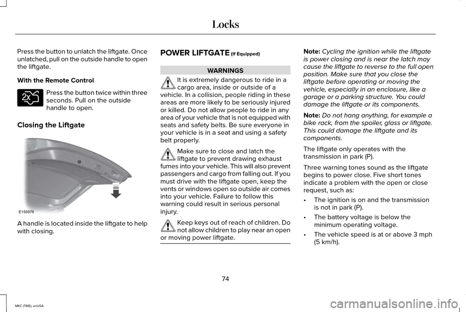
Closing the Liftgate A handle is located inside the liftgate to help
with closing. POWER LIFTGATE (If Equipped) WARNINGS
It is extremely dangerous to ride in a
cargo area, inside or outside of a
vehicle. In a collision, people riding in these
areas are more likely to be seriously injured
or killed. Do not allow people to ride in any
area of your vehicle that is not equipped with
seats and safety belts. Be sure everyone in
your vehicle is in a seat and using a safety
belt properly. Make sure to close and latch the
liftgate to prevent drawing exhaust
fumes into your vehicle. This will also prevent
passengers and cargo from falling out. If you
must drive with the liftgate open, keep the
vents or windows open so outside air comes
into your vehicle. Failure to follow this
warning could result in serious personal
injury. Keep keys out of reach of children. Do
not allow children to play near an open
or moving power liftgate. Note:
Cycling the ignition while the liftgate
is power closing and is near the latch may
cause the liftgate to reverse to the full open
position. Make sure that you close the
liftgate before operating or moving the
vehicle, especially in an enclosure, like a
garage or a parking structure. You could
damage the liftgate or its components.
Note: Do not hang anything, for example a
bike rack, from the spoiler, glass or liftgate.
This could damage the liftgate and its
components.
The liftgate only operates with the
transmission in park (P).
Three warning tones sound as the liftgate
begins to power close. Five short tones
indicate a problem with the open or close
request, such as:
• The ignition is on and the transmission
is not in park (P).
• The battery voltage is below the
minimum operating voltage.
• The vehicle speed is at or above
3 mph
(5 km/h).
74
MKC (TME), enUSA LocksE138630 E155976
Page 86 of 490
Memory Feature
You can save and recall the steering column
position with the memory function. See
Memory Function (page 145).
Pressing the adjustment control during
memory recall cancels the operation. The
column responds to the adjustment control.
The steering column sets a stopping position
just short of the end of the column position
to prevent damage to the steering column.
A new stopping position sets if the steering
column encounters an object when tilting or
telescoping.
To reset the steering column to its normal
stopping position:
1. Press the steering column control again after encountering the new stopping
position.
2. Continue pressing the control until it reaches the end of the column position.
A new stopping position is set. The next time
you tilt or telescope the steering column, it
will stop just short of the end of the column
position. Easy Entry and Exit Feature
When you switch the ignition off, the steering
column will move to the full up position to
allow extra room to exit your vehicle. The
column will return to the previous setting
when you switch the ignition on. You can
enable or disable this feature in the
information display.
See Information
Displays (page 112).
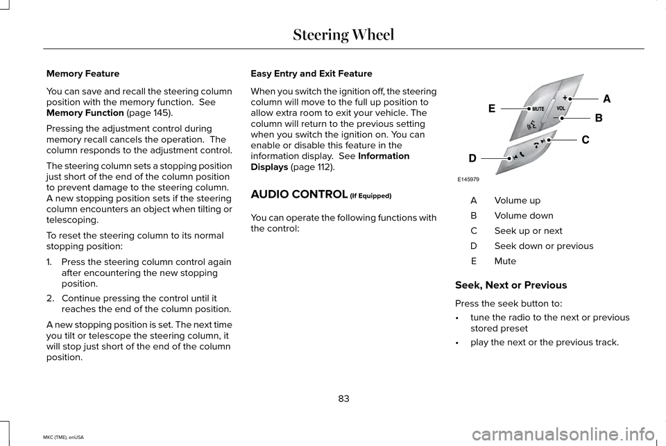
AUDIO CONTROL
(If Equipped)
You can operate the following functions with
the control: Volume up
A
Volume down
B
Seek up or next
C
Seek down or previous
D
MuteE
Seek, Next or Previous
Press the seek button to:
• tune the radio to the next or previous
stored preset
• play the next or the previous track.
83
MKC (TME), enUSA Steering WheelE145979
Page 96 of 490
Type 2 - Configurable
Note:
If this type is equipped, you are able
to switch the daytime running lamps on or
off using the information display controls.
See Information Displays (page 112).
When the daytime running lamps are
switched on in the information display and
you switch the ignition to the on position with
the lighting control in the autolamps position,
the daytime running lamps turn on whenever
the headlamps are off.
The other lighting control switch positions
do not activate the daytime running lamps
and can be used to temporarily override
autolamp control.
When switched off in the information display,
the daytime running lamps are off in all
lighting control switch positions. AUTOMATIC HIGH BEAM
CONTROL
(If Equipped)
The system will automatically turn on your
high beams if it is dark enough and no other
traffic is present. When it detects the
headlights of an approaching vehicle, the tail
lamps of the preceding vehicle or street
lighting, the system will turn off the high
beams before they distract other drivers. The
low beams remain on.
Note: If it appears that automatic control of
the high beams is not functioning properly,
check the windshield in front of the camera
for a blockage. A clear view of the road is
required for proper system operation. Have
any windshield damage in the area of the
camera ’s field-of-view repaired.
Note: If the system detects a blockage such
as bird droppings, bug splatter, snow or ice,
and you do not observe changes, the system
will go into low beam mode until you clear
the blockage. A message may also appear
in the instrument cluster display noting the
front camera is blocked. Note:
Typical road dust, dirt and water spots
will not affect the performance of the
automatic high beam system . However, in
cold or inclement weather conditions, you
will notice a decrease in the availability of
the high beam system, especially at start up.
If you want to change the beam state
independently of the system, you may switch
the high beams on or off using the
multifunction switch. Automatic control will
resume when conditions are correct.
Note: Modification of the vehicle ride height
such as using much larger tires, may
degrade feature performance.
A camera sensor, centrally mounted behind
the windshield of your vehicle, continuously
monitors conditions to decide when to switch
the high beams off and on.
Once the system is active, the high beams
will switch on if:
• the ambient light level is low enough
• there is no traffic in front of the vehicle
• the vehicle speed is greater than 25 mph
(40 km/h)
93
MKC (TME), enUSA Lighting
Page 110 of 490
Variations:
Distance-to-empty
Fuel gauge position
Driving type (fuel economy conditions)
35 miles to 80 miles (56 km to 129 km)
1/16th
Highway driving
35 miles (56km)
1/16th
Severe duty driving (trailer towing, extended idle)
Engine Coolant Temperature Gauge
Indicates engine coolant temperature. At
normal operating temperature, the level
indicator will be in the normal range. If the
engine coolant temperature exceeds the
normal range, stop your vehicle as soon as
safely possible, switch off the engine and let
the engine cool. WARNING
Never remove the coolant reservoir
cap while the engine is running or hot. WARNING LAMPS AND
INDICATORS
The following warning lamps and indicators
will alert you to a vehicle condition that may
become serious. Some lamps will illuminate
when you start your vehicle to make sure
they work. If any lamps remain on after
starting your vehicle, refer to the respective
system warning lamp for further information.
Note:
Some warning indicators appear in
the information display and function the
same as a warning lamp, but do not display
when you start your vehicle. Adaptive Cruise Control (If Equipped) The speed control system indicator
light changes color to indicate
what mode the system is in:
See
Using Adaptive Cruise Control (page 204).
On (white light): Illuminates when you turn
the adaptive cruise control system on. Turns
off when you turn the speed control system
off.
Engaged (green light): Illuminates when the
adaptive cruise control system engages.
Turns off when the speed control system is
disengaged.
107
MKC (TME), enUSA Instrument ClusterE144524