AUX LINCOLN MKT 2014 Owners Manual
[x] Cancel search | Manufacturer: LINCOLN, Model Year: 2014, Model line: MKT, Model: LINCOLN MKT 2014Pages: 498, PDF Size: 7.3 MB
Page 4 of 498
Front fog lamps......................................101
Adaptive headlamps...................................101
Turn signal control....................................102
Interior lamps........................................102
Windows and Mirrors 105
Power windows......................................105
Exteriormirrors......................................107
Interior mirrors......................................109
Sun visors..........................................110
Moonroof...........................................110
Instrument Cluster 113
Gauges.............................................113
Warning lamps and indicators............................113
Audible warnings and indicators..........................118
Information Displays 119
Controls............................................119
Information messages..................................125
Climate Control 135
Dual automatic temperature control........................135
Auxiliary passenger climate control........................136
Rear window defroster.................................138
Cabin air filter.......................................139
Seats 141
Sitting in the correct position............................141
Head restraints.......................................142
Power seats.........................................145
Memory function.....................................146
Heated seats........................................148
Heated and ventilated seats..............................149
Rear seats..........................................151
Table of Contents3
2014 MKT(mkt)
Owners Guide gf, 1st Printing, April 2013
USA(fus)
Page 5 of 498
Universal Garage Door Opener (If Equipped) 162
HomeLink® wireless control system.......................162
Auxiliary Power Points 167
Storage Compartments 170
Center console.......................................170
Overhead console.....................................172
Starting and Stopping the Engine 173
Engine block heater...................................177
Fuel and Refueling 179
Fuel quality.........................................180
Running out of fuel....................................181
Refueling...........................................182
Fuel consumption.....................................184
Transmission 188
Automatic transmission.................................188
All-Wheel Drive (If Equipped) 193
All wheel drive.......................................193
Brakes 200
Brakes.............................................200
Hints on driving with anti-lock brakes......................201
Parking brake........................................201
Traction Control 202
TractionControl™ ....................................202
Stability Control 203
AdvanceTrac®.......................................204
Parking Aids 205
Sensing system.......................................205
Active park assist.....................................206
Rear-view camera system...............................211
4Table of Contents
2014 MKT(mkt)
Owners Guide gf, 1st Printing, April 2013
USA(fus)
Page 168 of 498
AUXILIARY POWER POINTS
WARNING:Do not plug optional electrical accessories into the
cigarette lighter socket (if equipped). Improper use of the lighter
can cause damage not covered by your warranty, and can result in fire
or serious injury.
Note:If used when the engine is not running, the battery will discharge.
There may be insufficient power to restart your engine.
Note:Do not insert objects other than an accessory plug into the power
point. This will damage the outlet and blow the fuse.
Note:Do not hang any type of accessory or accessory bracket from the
plug.
Note:Do not use the power point over the vehicle capacity of 12 volt
DC 180 watts or a fuse may blow.
Note:Do not use the power point for operating a cigarette lighter
element.
Note:Improper use of the power outlet can cause damage not covered
by your warranty.
Note:Always keep the power point caps closed when not in use.
Run the engine for full capacity use of the power point. To prevent the
battery from being discharged:
•Do not use the power point longer than necessary when the engine is
not running.
•Do not leave devices plugged in overnight or when the vehicle is
parked for extended periods.
Locations
Power points may be found:
•near the floor in the front console bin on the driver’s side
•in the center console storage compartment
•on the rear of the center console (inside the second row center
console on vehicle equipped with that feature)
•in the rear cargo area on the left rear trim panel.
Auxiliary Power Points167
2014 MKT(mkt)
Owners Guide gf, 1st Printing, April 2013
USA(fus)
Page 169 of 498
110 Volt AC Power Point (If Equipped)
WARNING:Do not keep electrical devices plugged in the power
point whenever the device is not in use. Do not use any
extension cord with the 110 volt AC power point, since it will defeat
the safety protection design. Doing so my cause the power point to
overload due to powering multiple devices that can reach beyond the
150 watt load limit and could result in fire or serious injury.
Note:The cap should always be closed whenever the power point outlet
is not in use.
Note:Keep the engine running to use the power point.
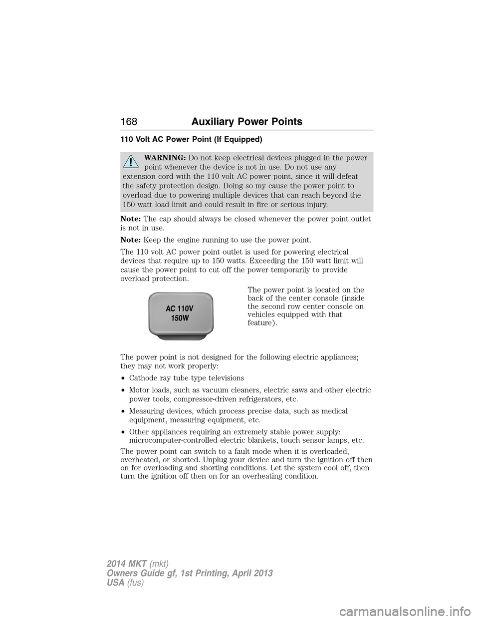
The 110 volt AC power point outlet is used for powering electrical
devices that require up to 150 watts. Exceeding the 150 watt limit will
cause the power point to cut off the power temporarily to provide
overload protection.
The power point is located on the
back of the center console (inside
the second row center console on
vehicles equipped with that
feature).
The power point is not designed for the following electric appliances;
they may not work properly:
•Cathode ray tube type televisions
•Motor loads, such as vacuum cleaners, electric saws and other electric
power tools, compressor-driven refrigerators, etc.
•Measuring devices, which process precise data, such as medical
equipment, measuring equipment, etc.
•Other appliances requiring an extremely stable power supply:
microcomputer-controlled electric blankets, touch sensor lamps, etc.
The power point can switch to a fault mode when it is overloaded,
overheated, or shorted. Unplug your device and turn the ignition off then
on for overloading and shorting conditions. Let the system cool off, then
turn the ignition off then on for an overheating condition.
168Auxiliary Power Points
2014 MKT(mkt)
Owners Guide gf, 1st Printing, April 2013
USA(fus)
Page 170 of 498
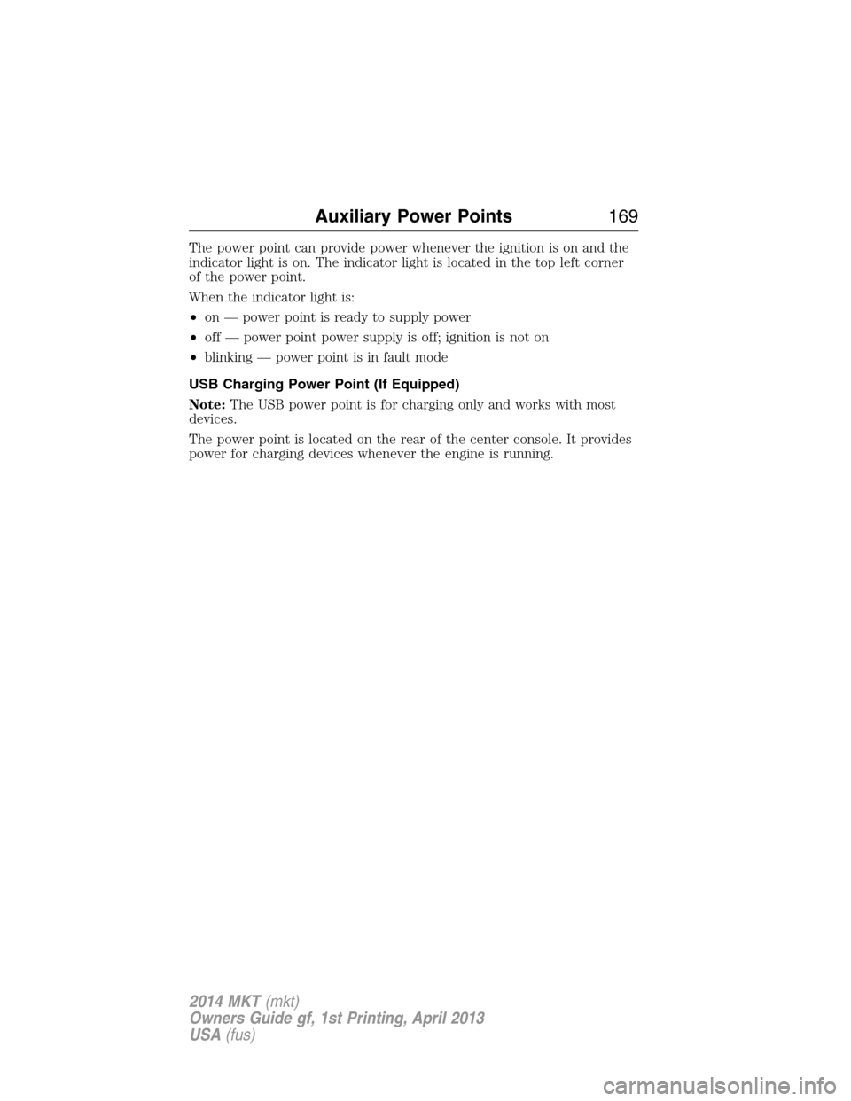
The power point can provide power whenever the ignition is on and the
indicator light is on. The indicator light is located in the top left corner
of the power point.
When the indicator light is:
•on — power point is ready to supply power
•off — power point power supply is off; ignition is not on
•blinking — power point is in fault mode
USB Charging Power Point (If Equipped)
Note:The USB power point is for charging only and works with most
devices.
The power point is located on the rear of the center console. It provides
power for charging devices whenever the engine is running.
Auxiliary Power Points169
2014 MKT(mkt)
Owners Guide gf, 1st Printing, April 2013
USA(fus)
Page 283 of 498
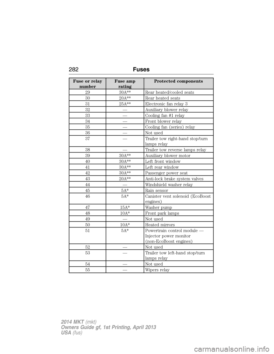
Fuse or relay
numberFuse amp
ratingProtected components
29 30A** Rear heated/cooled seats
30 20A** Rear heated seats
31 25A** Electronic fan relay 3
32 — Auxiliary blower relay
33 — Cooling fan #1 relay
34 — Front blower relay
35 — Cooling fan (series) relay
36 — Not used
37 — Trailer tow right-hand stop/turn
lamps relay
38 — Trailer tow reverse lamps relay
39 30A** Auxiliary blower motor
40 30A** Left front window
41 30A** Left rear window
42 30A** Passenger power seat
43 20A** Anti-lock brake system valves
44 — Windshield washer relay
45 5A* Rain sensor
46 5A* Canister vent solenoid (EcoBoost
engines)
47 15A* Washer pump
48 10A* Front park lamps
49 — Not used
50 10A* Heated mirrors
51 5A* Powertrain control module —
Injector power monitor
(non-EcoBoost engines)
52 — Not used
53 — Trailer tow left-hand stop/turn
lamps relay
54 — Not used
55 — Wipers relay
282Fuses
2014 MKT(mkt)
Owners Guide gf, 1st Printing, April 2013
USA(fus)
Page 284 of 498
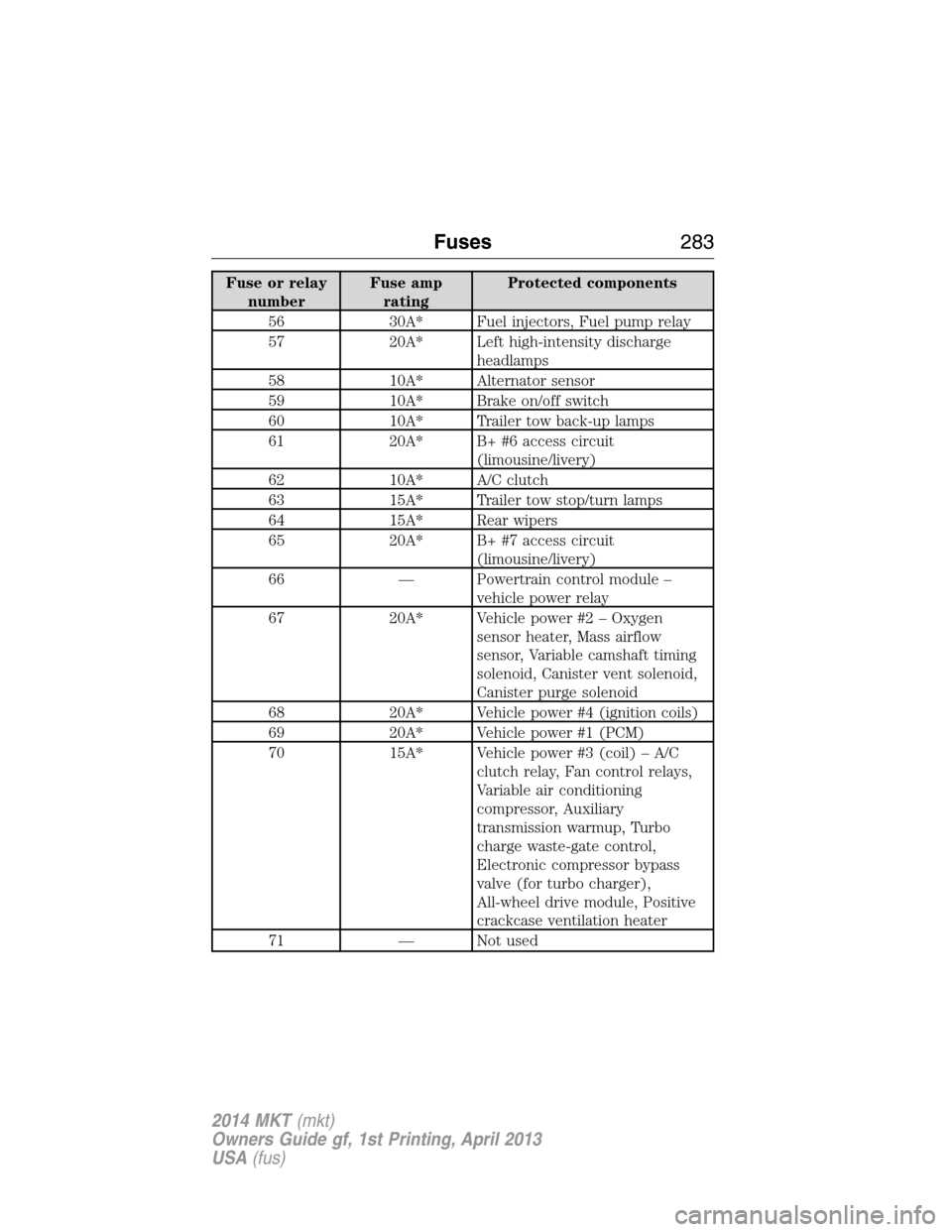
Fuse or relay
numberFuse amp
ratingProtected components
56 30A* Fuel injectors, Fuel pump relay
57 20A* Left high-intensity discharge
headlamps
58 10A* Alternator sensor
59 10A* Brake on/off switch
60 10A* Trailer tow back-up lamps
61 20A* B+ #6 access circuit
(limousine/livery)
62 10A* A/C clutch
63 15A* Trailer tow stop/turn lamps
64 15A* Rear wipers
65 20A* B+ #7 access circuit
(limousine/livery)
66 — Powertrain control module –
vehicle power relay
67 20A* Vehicle power #2 – Oxygen
sensor heater, Mass airflow
sensor, Variable camshaft timing
solenoid, Canister vent solenoid,
Canister purge solenoid
68 20A* Vehicle power #4 (ignition coils)
69 20A* Vehicle power #1 (PCM)
70 15A* Vehicle power #3 (coil) – A/C
clutch relay, Fan control relays,
Variable air conditioning
compressor, Auxiliary
transmission warmup, Turbo
charge waste-gate control,
Electronic compressor bypass
valve (for turbo charger),
All-wheel drive module, Positive
crackcase ventilation heater
71 — Not used
Fuses283
2014 MKT(mkt)
Owners Guide gf, 1st Printing, April 2013
USA(fus)
Page 286 of 498
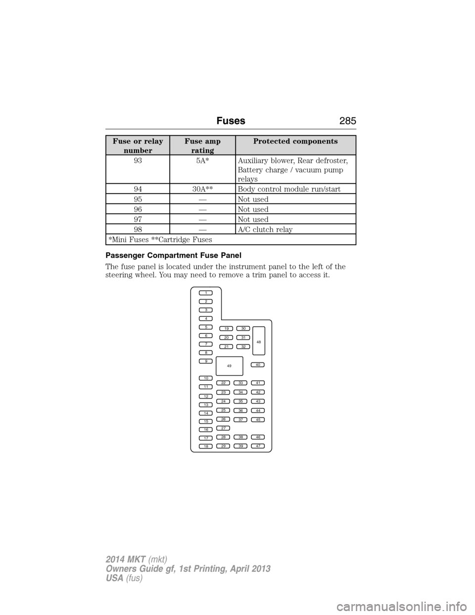
Fuse or relay
numberFuse amp
ratingProtected components
93 5A* Auxiliary blower, Rear defroster,
Battery charge / vacuum pump
relays
94 30A** Body control module run/start
95 — Not used
96 — Not used
97 — Not used
98 — A/C clutch relay
*Mini Fuses **Cartridge Fuses
Passenger Compartment Fuse Panel
The fuse panel is located under the instrument panel to the left of the
steering wheel. You may need to remove a trim panel to access it.
1
2
3
4
5
6
7
8
9
10
11
12
13
14
15
16
17
18
19
20
21
223341
42
43
44
45
34
35
36
37
23
24
25
26
27
283846
394729
32
40
31
30
48
49
Fuses285
2014 MKT(mkt)
Owners Guide gf, 1st Printing, April 2013
USA(fus)
Page 291 of 498
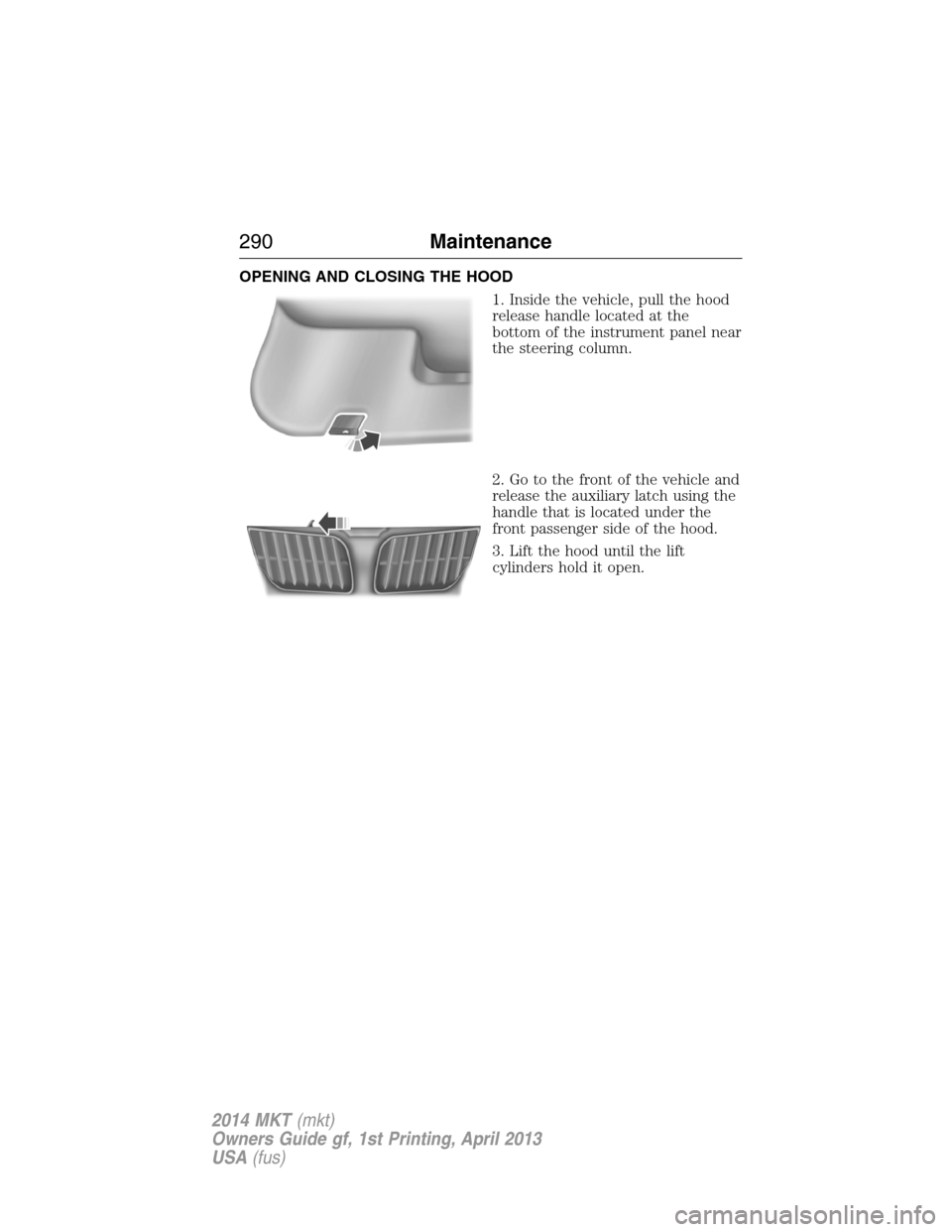
OPENING AND CLOSING THE HOOD
1. Inside the vehicle, pull the hood
release handle located at the
bottom of the instrument panel near
the steering column.
2. Go to the front of the vehicle and
release the auxiliary latch using the
handle that is located under the
front passenger side of the hood.
3. Lift the hood until the lift
cylinders hold it open.
290Maintenance
2014 MKT(mkt)
Owners Guide gf, 1st Printing, April 2013
USA(fus)
Page 361 of 498

TECHNICAL SPECIFICATIONS
Items CapacityFord Part Name or
equivalentFord Part Number /
Ford Specification
Brake fluid
1
Between MAX and
MIN on reservoirMotorcraft DOT 4 LV
High Performance Motor
Vehicle Brake FluidPM-20 /
WSS-M6C65-A2 and ISO
4925 Class 6
Door latch, hood latch,
auxiliary hood latch,
seat tracks, trunk and
liftgate latches—Multi-Purpose Grease
(Lithium grease)XG-4 or XL-5 or
equivalent /
ESA-M1C93-B
Lock cylinders —Motorcraft Penetrating
and Lock LubricantXL-1 /
None
Automatic transmission
fluid
2,3
9.0 quarts (8.5L)
(6F35)
Motorcraft
MERCON LV ATFXT-10-QLV /
MERCON™ LV 10.9 quarts
(10.3L)
(6F50)
11.6 quarts
(11.0L)
(6F55)
Rear differential (AWD)
fluid1.3 pints (0.615L)Motorcraft SAE 80W-90
Premium Rear Axle
LubricantXY-80W90-QL /
WSP-M2C197-A
Power Transfer Unit
(PTU) fluid (AWD)
4
18 ounces (0.53L)Motorcraft SAE 75W-140
Synthetic Rear Axle
LubricantXY-75W140-QL /
WSL-M2C192-A
360Capacities and Specifications
2014 MKT(mkt)
Owners Guide gf, 1st Printing, April 2013
USA(fus)