headlamp LINCOLN MKT 2016 User Guide
[x] Cancel search | Manufacturer: LINCOLN, Model Year: 2016, Model line: MKT, Model: LINCOLN MKT 2016Pages: 452, PDF Size: 4.69 MB
Page 110 of 452
If the light is blinking, engine misfire is
occurring which could damage your catalytic
converter. Drive in a moderate fashion (avoid
heavy acceleration and deceleration) and
have your vehicle serviced immediately.
WARNING
Under engine misfire conditions,
excessive exhaust temperatures could
damage the catalytic converter, the fuel
system, interior floor coverings or other
vehicle components, possibly causing a fire.
Have an authorized dealer service your
vehicle immediately. The service engine soon indicator light
illuminates when the ignition is first turned
on prior to engine start to check the bulb and
to indicate whether the vehicle is ready for
Inspection/Maintenance (I/M) testing.
Normally, the service engine soon light will
stay on until the engine is cranked, then turn
itself off if no malfunctions are present.
However, if after 15 seconds the service
engine soon light blinks eight times, it means
that the vehicle is not ready for I/M testing.
See Emission Control System (page 173).Stability Control It will flash when the system is
active. If it remains illuminated or
does not illuminate when you
switch the ignition on, this indicates a
malfunction. During a malfunction the system
will switch off. Have the system checked by
your authorized dealer immediately.
See
Using Stability Control (page 195).
Stability Control Off It will illuminate when you switch
the system off. It will go out when
you switch the system back on or
when you switch the ignition off. See Using
Stability Control
(page 195). AUDIBLE WARNINGS AND
INDICATORS
Keyless Warning Alert
The horn will sound twice when you exit your
vehicle with the intelligent access key and
your vehicle is in RUN, indicating your vehicle
is still on.
Headlamps On Warning Chime
Sounds when you remove the key from the
ignition and open the driver's door and you
have left the headlamps or parking lamps
on.
Parking Brake On Warning Chime
Sounds when you have left the parking brake
on and drive your vehicle. If the warning
chime remains on after you have released
the parking brake, have the system checked
by your authorized dealer immediately.
107
MKT (), enUSA, First Printing Instrument ClusterE138639
Page 165 of 452
Note:
You may have to press the push
button ignition switch twice to switch the
ignition on.
Start: Starts the engine.
• Press the brake pedal, and then press
the button for any length of time. An
indicator light on the button illuminates
when then ignition is on and when the
engine starts.
STARTING A GASOLINE ENGINE
When you start the engine, the idle speed
increases. This helps to warm up the engine.
If the engine idle speed does not slow down
automatically, have your vehicle checked by
an authorized dealer. Note:
You can crank the engine for a total
of 60 seconds without the engine starting
before the starting system temporarily
disables. The 60 seconds does not have to
be all at once. For example, if you crank the
engine three times for 20 seconds each time,
without the engine starting, you reached the
60-second time limit. A message appears
in the information display alerting you that
you exceeded the cranking time. You
cannot attempt to start the engine for at
least 15 minutes. After 15 minutes, you are
limited to a 15-second engine cranking time.
You need to wait 60 minutes before you can
crank the engine for 60 seconds again.
Before starting your vehicle, check the
following:
• Make sure all occupants have fastened
their safety belts.
• Make sure the headlamps and electrical
accessories are off.
• Make sure the parking brake is on.
• Make sure the transmission is in park (P).
Note: Do not touch the accelerator pedal. Note:
You must have your intelligent access
key in your vehicle to shift the transmission
out of park (P).
1. Fully depress the brake pedal.
2. Press the push button ignition switch.
The system does not function if:
• The passive key frequencies are jammed.
• The key battery has no charge.
If you are unable to start your vehicle, do the
following:
162
MKT (), enUSA, First Printing Starting and Stopping the Engine
Page 222 of 452
•
The road has no or poor lane markings
in the camera field-of-view.
• The camera is obscured or unable to
detect the lane markings due to
environmental conditions (significant sun
angles, shadows, snow, heavy rain or
fog), traffic conditions (following a large
vehicle that is blocking or shadowing the
lane), or vehicle conditions (poor
headlamp illumination). See Troubleshooting for additional
information.
Green: Indicates that the system is available
or ready to provide a warning or intervention,
on the indicated side(s).
Yellow: Indicates that the system is providing
or has just provided a lane keeping aid
intervention. Red: Indicates that the system is providing
or has just provided a lane keeping alert
warning.
The system can be temporarily suppressed
at any time by the following:
•
Quick braking.
• Fast acceleration.
• Using the turn signal indicator.
• Evasive steering maneuver.
Troubleshooting Why is the feature not available (line markings are gray) when I can s\
ee the lane markings on the road?
Vehicle speed is outside the operational range of the feature
Sun is shining directly into the camera lens
Quick intentional lane change
Staying too close to the lane marking
Driving at high speeds in curves
The last Alert warning or Aid intervention occurred a short time ago
Ambiguous lane markings (mainly in construction zones)
Rapid transition from light to dark or vice versa
219
MKT (), enUSA, First Printing Driving Aids
Page 235 of 452
System Limitations
WARNING
The collision warning system
’s brake
support can only help reduce the
speed at which a collision occurs if the driver
applies the vehicle ’s brakes. The brake pedal
must be pressed just like any typical braking
situation. Due to the nature of radar technology, there
may be certain instances where vehicles do
not provide a collision warning. These
include:
•
Stationary vehicles or vehicles moving
below 6 mph (10 km/h).
• Pedestrians or objects in the roadway.
• Oncoming vehicles in the same lane.
• Severe weather conditions (see blocked
sensor section).
• Debris build-up on the grille near the
headlamps (see blocked sensor section).
• Small distance to vehicle ahead.
• Steering wheel and pedal movements
are large (very active driving style). If the front end of the vehicle is hit or
damaged, the radar sensing zone may be
altered causing missed or false collision
warnings. See your authorized dealer to have
your collision warning radar checked for
proper coverage and operation.
DRIVE CONTROL (If Equipped)
LINCOLN DRIVE CONTROL
Lincoln Drive Control delivers the Lincoln
driving experience through a suite of
sophisticated electronic vehicle systems.
These systems continuously monitor your
driving inputs and the road conditions to
optimize ride comfort, steering, handling,
powertrain response and sound. You can
preset your preferences for these systems
within the information display. Lincoln Drive
Control will respond to your preferences
based on what gear position you select. This
provides a single location to control multiple
systems performance settings. Lincoln Drive Control consists of the
following systems:
•
Continuously controlled damping
dynamically adjusts the shock absorbers
stiffness in real time to match the road
surface and driver inputs. This system
continuously monitors your vehicle ’s
motion (roll, pitch, bounce), suspension
position, load, speed, road conditions,
and steering to adjust the suspension
damping for optimal vehicle control.
• Electronically power-assisted steering
adjusts steering effort and feel based on
your vehicle speed and your inputs.
• Active noise control utilizes your vehicle
electronics to enhance the acoustic
experience.
• Electronic stability control and traction
control maintain your vehicle control in
adverse conditions or high performance
driving.
• Electronic throttle control enhances the
powertrain response to your inputs.
232
MKT (), enUSA, First Printing Driving Aids
Page 277 of 452
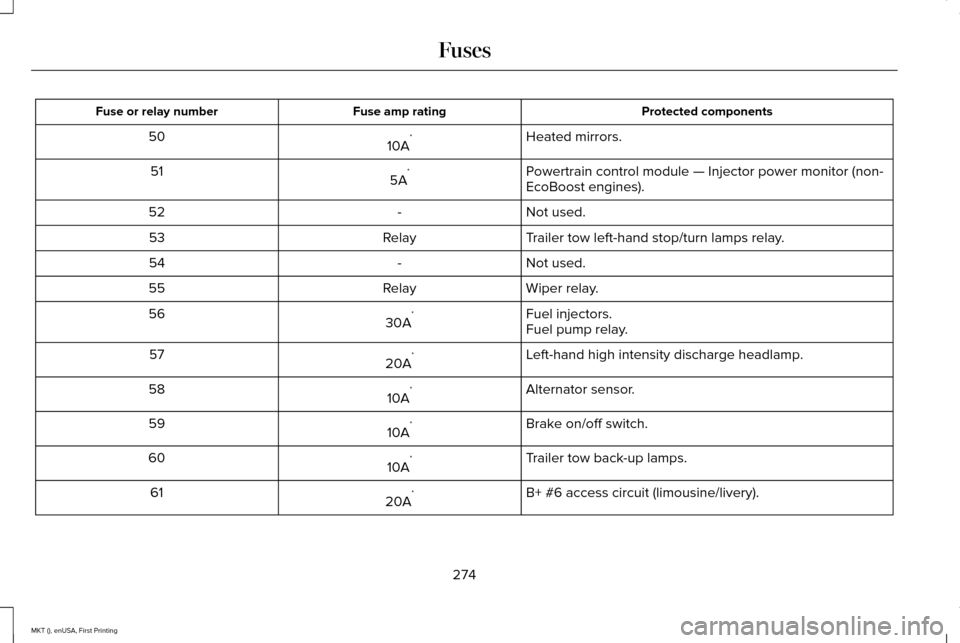
Protected components
Fuse amp rating
Fuse or relay number
Heated mirrors.
10A *
50
Powertrain control module — Injector power monitor (non-
EcoBoost engines).
5A *
51
Not used.
-
52
Trailer tow left-hand stop/turn lamps relay.
Relay
53
Not used.
-
54
Wiper relay.
Relay
55
Fuel injectors.
30A *
56
Fuel pump relay.
Left-hand high intensity discharge headlamp.
20A *
57
Alternator sensor.
10A *
58
Brake on/off switch.
10A *
59
Trailer tow back-up lamps.
10A *
60
B+ #6 access circuit (limousine/livery).
20A *
61
274
MKT (), enUSA, First Printing Fuses
Page 279 of 452
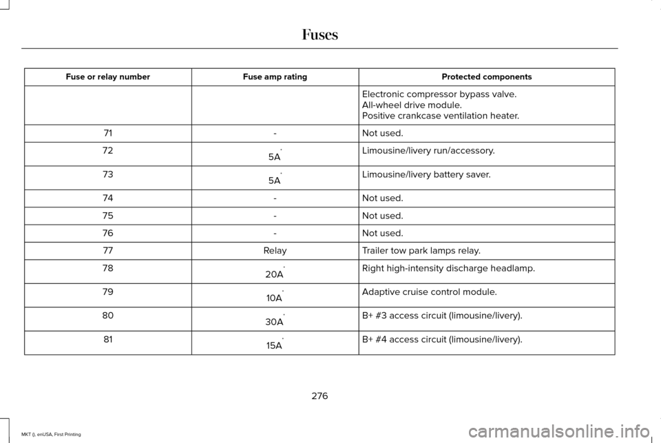
Protected components
Fuse amp rating
Fuse or relay number
Electronic compressor bypass valve.
All-wheel drive module.
Positive crankcase ventilation heater.
Not used.
-
71
Limousine/livery run/accessory.
5A *
72
Limousine/livery battery saver.
5A *
73
Not used.
-
74
Not used.
-
75
Not used.
-
76
Trailer tow park lamps relay.
Relay
77
Right high-intensity discharge headlamp.
20A *
78
Adaptive cruise control module.
10A *
79
B+ #3 access circuit (limousine/livery).
30A *
80
B+ #4 access circuit (limousine/livery).
15A *
81
276
MKT (), enUSA, First Printing Fuses
Page 280 of 452
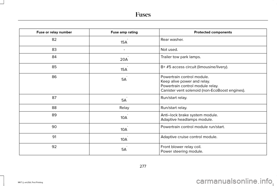
Protected components
Fuse amp rating
Fuse or relay number
Rear washer.
15A *
82
Not used.
-
83
Trailer tow park lamps.
20A *
84
B+ #5 access circuit (limousine/livery).
15A *
85
Powertrain control module.
5A *
86
Keep alive power and relay.
Powertrain control module relay.
Canister vent solenoid (non-EcoBoost engines).
Run/start relay.
5A *
87
Run/start relay.
Relay
88
Anti–lock brake system module.
10A *
89
Adaptive headlamps module.
Powertrain control module run/start.
10A *
90
Adaptive cruise control module.
10A *
91
Front blower relay coil.
5A *
92
Power steering module.
277
MKT (), enUSA, First Printing Fuses
Page 284 of 452
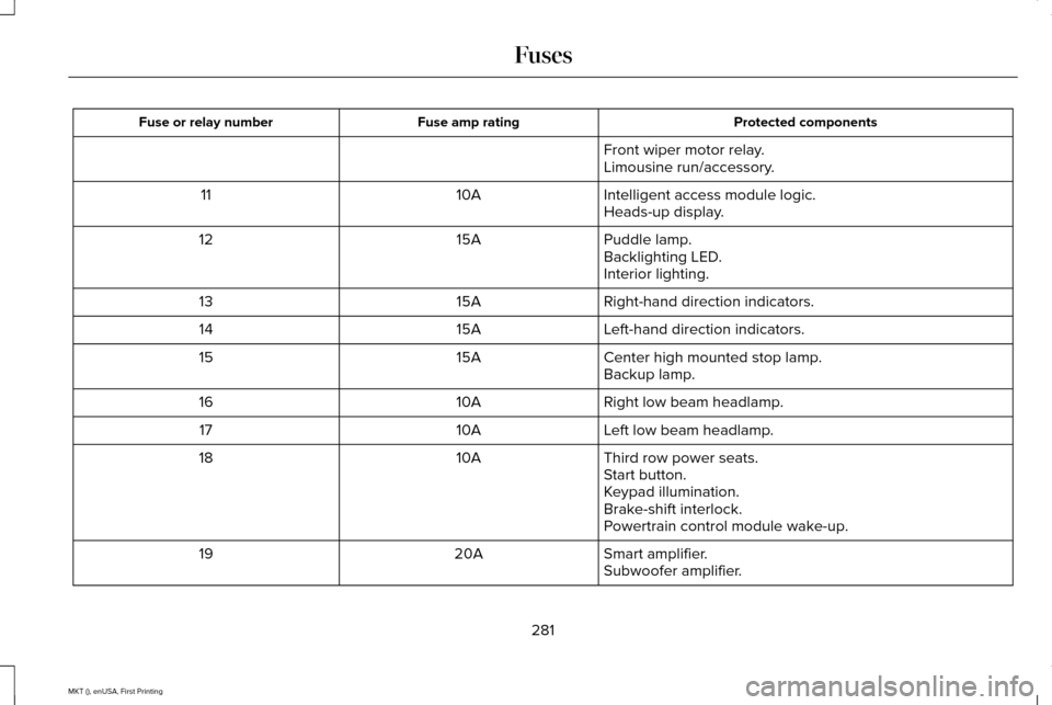
Protected components
Fuse amp rating
Fuse or relay number
Front wiper motor relay.
Limousine run/accessory.
Intelligent access module logic.
10A
11
Heads-up display.
Puddle lamp.
15A
12
Backlighting LED.
Interior lighting.
Right-hand direction indicators.
15A
13
Left-hand direction indicators.
15A
14
Center high mounted stop lamp.
15A
15
Backup lamp.
Right low beam headlamp.
10A
16
Left low beam headlamp.
10A
17
Third row power seats.
10A
18
Start button.
Keypad illumination.
Brake-shift interlock.
Powertrain control module wake-up.
Smart amplifier.
20A
19
Subwoofer amplifier.
281
MKT (), enUSA, First Printing Fuses
Page 309 of 452
1. Remove the wiper blade.
2. Install in the reverse order.
Note:
Make sure that the wiper blade locks
into place.
ADJUSTING THE HEADLAMPS
Vertical Aim Adjustment
The assembly plant properly aims the
headlamps on your vehicle. If your vehicle
has been in an accident, have the alignment
of your headlamps checked by your
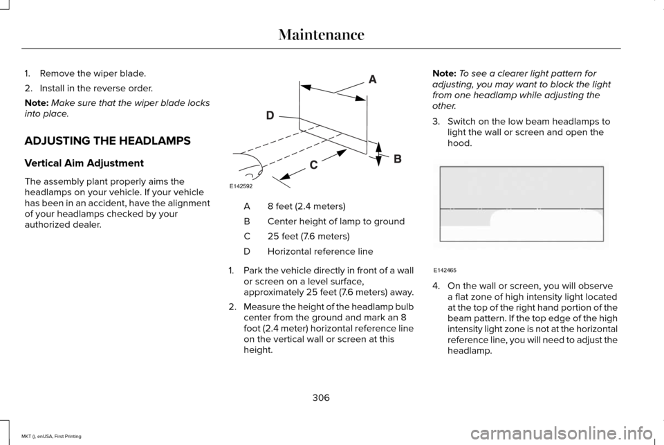
authorized dealer. 8 feet (2.4 meters)
A
Center height of lamp to ground
B
25 feet (7.6 meters)
C
Horizontal reference line
D
1. Park the vehicle directly in front of a wall
or screen on a level surface,
approximately 25 feet (7.6 meters) away.
2. Measure the height of the headlamp bulb
center from the ground and mark an 8
foot (2.4 meter) horizontal reference line
on the vertical wall or screen at this
height. Note:
To see a clearer light pattern for
adjusting, you may want to block the light
from one headlamp while adjusting the
other.
3. Switch on the low beam headlamps to light the wall or screen and open the
hood. 4. On the wall or screen, you will observe
a flat zone of high intensity light located
at the top of the right hand portion of the
beam pattern. If the top edge of the high
intensity light zone is not at the horizontal
reference line, you will need to adjust the
headlamp.
306
MKT (), enUSA, First Printing MaintenanceE142592 E142465
Page 310 of 452
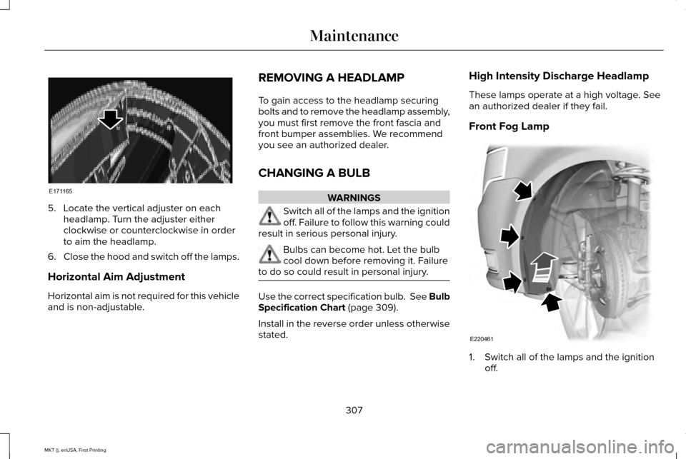
5. Locate the vertical adjuster on each
headlamp. Turn the adjuster either
clockwise or counterclockwise in order
to aim the headlamp.
6. Close the hood and switch off the lamps.
Horizontal Aim Adjustment
Horizontal aim is not required for this vehicle
and is non-adjustable. REMOVING A HEADLAMP
To gain access to the headlamp securing
bolts and to remove the headlamp assembly,
you must first remove the front fascia and
front bumper assemblies. We recommend
you see an authorized dealer.
CHANGING A BULB WARNINGS
Switch all of the lamps and the ignition
off. Failure to follow this warning could
result in serious personal injury. Bulbs can become hot. Let the bulb
cool down before removing it. Failure
to do so could result in personal injury. Use the correct specification bulb. See Bulb
Specification Chart (page 309).
Install in the reverse order unless otherwise
stated. High Intensity Discharge Headlamp
These lamps operate at a high voltage. See
an authorized dealer if they fail.
Front Fog Lamp
1. Switch all of the lamps and the ignition
off.
307
MKT (), enUSA, First Printing MaintenanceE171165 E220461