stop start LINCOLN MKZ 2016 Owner's Guide
[x] Cancel search | Manufacturer: LINCOLN, Model Year: 2016, Model line: MKZ, Model: LINCOLN MKZ 2016Pages: 544, PDF Size: 5.77 MB
Page 280 of 544
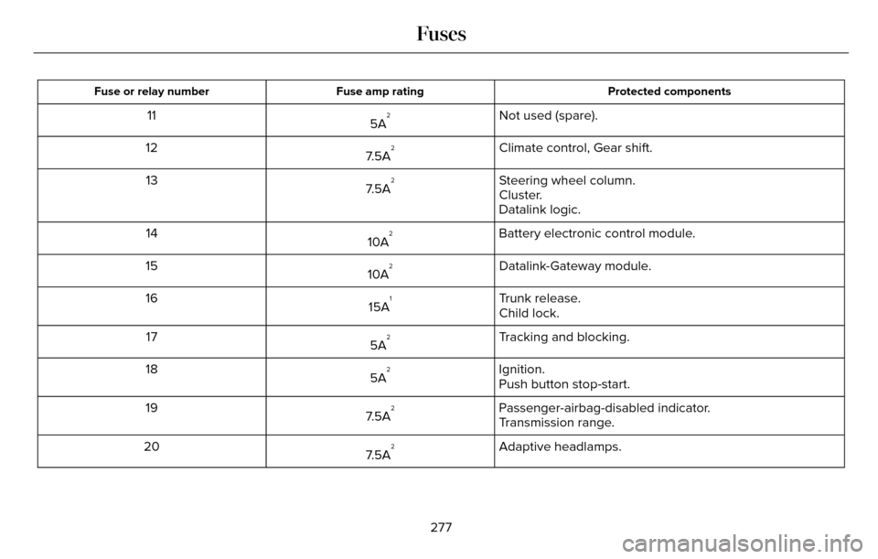
Protected components
Fuse amp rating
Fuse or relay number
Not used (spare).
5A211
Climate control, Gear shift.
7.5A
212
Steering wheel column.
7.5A
213
Cluster.
Datalink logic.
Battery electronic control module.
10A
214
Datalink-Gateway module.
10A
215
Trunk release.
15A
116
Child lock.
Tracking and blocking.
5A
217
Ignition.
5A
218
Push button stop-start.
Passenger-airbag-disabled indicator.
7.5A
219
Transmission range.
Adaptive headlamps.
7.5A
220
277
Fuses
Page 301 of 544
If you see any corrosion on the battery or
terminals, remove the cables from the
terminals and clean with a wire brush. You
can neutralize the acid with a solution of
baking soda and water.
When a battery replacement is required, the
battery should only be replaced with a Ford
recommended replacement battery that
matches the electrical requirements of the
vehicle.
Because your vehicle’s engine is
electronically-controlled by a computer,
some engine control settings are maintained
by power from the low voltage battery. Some
engine computer settings, like the idle trim
and fuel trim strategy, optimize the
driveability and performance of the engine.
Some other computer settings, like the clock
and radio station presets, are also maintained
in memory by power from the low voltage
battery. When a technician disconnects and
connects the low voltage battery, these
settings are erased.Note:
Until you switch the ignition to the on
position, you will receive a message in your
information display stating that your vehicle
is not in park.
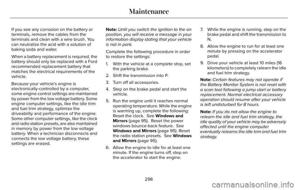
Complete the following procedure in order
to restore the settings:
1. With the vehicle at a complete stop, set the parking brake.
2. Shift the transmission into P.
3. Turn off all accessories.
4. Step on the brake pedal and start the vehicle.
5. Run the engine until it reaches normal operating temperature. While the engine
is warming up, complete the following:
Reset the clock. See Windows and
Mirrors (page 95). Reset the power
windows bounce-back feature. See
Windows and Mirrors (page 95). Reset
the radio station presets. See Windows
and Mirrors (page 95).
6. Allow the engine to idle for at least one minute. If the engine turns off, step on
the accelerator to start the engine. 7. While the engine is running, step on the
brake pedal and shift the transmission to
N.
8. Allow the engine to run for at least one minute by pressing on the accelerator
pedal.
9. Drive your vehicle at least 10 miles (16 kilometers) to completely relearn the idle
and fuel trim strategy.
Note: Certain features may not operate if
the Battery Monitor System is not reset with
a scan tool following a jump start or battery
replacement. Normal electrical accessory
operation should resume after your vehicle
is left undisturbed for 8 hours.
Note: If you do not allow the engine to
relearn the idle and fuel trim strategy, the
idle quality of your vehicle may be adversely
affected until the engine computer
eventually relearns the idle trim and fuel trim
strategy.
298
Maintenance
Page 319 of 544
What to do when a Tire Is Punctured
A tire puncture within the tire tread area can
be repaired in two stages with the kit.
• In the first stage, the tire will be reinflatedwith a sealing compound and air. After
the tire has been reinflated, you will need
to drive the vehicle a short distance 4 mi
(6 km) to distribute the sealant in the tire.
• In the second stage, you will need to check the tire pressure and adjust, if
necessary, to the vehicle tire inflation
pressure.
First Stage: Reinflating the Tire with
Sealing Compound and Air
WARNINGS
Do not stand directly over the kit while
inflating the tire. If you notice any
unusual bulges or deformations in the tire
sidewall during inflation, stop and call
roadside assistance.
If the tire does not inflate to the
recommended tire pressure within 15
minutes, stop and call roadside assistance.
Preparation: Park the vehicle in a safe, level
and secure area, away from moving traffic.
Turn the hazard lights on. Apply the parking
brake and turn the engine off. Inspect the
flat tire for visible damage.
Sealant compound contains latex. To avoid
any allergic reactions, use the non-latex
gloves located in the accessory box on the
underside of the kit housing.
Do not remove any foreign object that has
pierced the tire. If a puncture is located in
the tire sidewall, stop and call roadside
assistance.
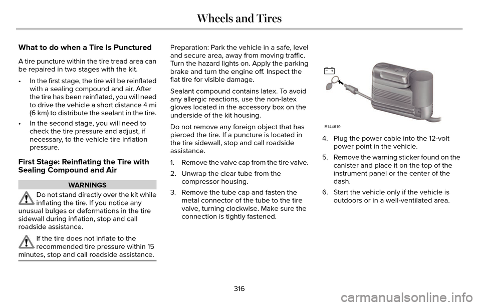
1. Remove the valve cap from the tire valve.
2. Unwrap the clear tube from the compressor housing.
3. Remove the tube cap and fasten the metal connector of the tube to the tire
valve, turning clockwise. Make sure the
connection is tightly fastened.
E144619
4. Plug the power cable into the 12-voltpower point in the vehicle.
5. Remove the warning sticker found on the canister and place it on the top of the
instrument panel or the center of the
dash.
6. Start the vehicle only if the vehicle is outdoors or in a well-ventilated area.
316
Wheels and Tires
Page 342 of 544
WARNINGS
1. Make sure that you have the correct
tire and wheel size.
2. Lubricate the tire bead and wheel
bead seat area again.
3. Stand at a minimum of 12 feet (3.66
meters) away from the wheel and tire
assembly.
4. Use both eye and ear protection.
For a mounting pressure more than 20
psi (1.38 bar) greater than the maximum
pressure, a Ford dealer or other tire
service professional should do the
mounting.
Always inflate steel carcass tires with a
remote air fill with the person inflating
standing at a minimum of 12 feet (3.66
meters) away from the wheel and tire
assemblyImportant: Remember to replace the
wheel valve stems when the road tires
are replaced on your vehicle
It is recommended that the two front
tires or two rear tires generally be
replaced as a pair.
The tire pressure sensors mounted in
the wheels (originally installed on your
vehicle) are not designed to be used in
aftermarket wheels.
The use of wheels or tires not
recommended by Ford Motor Company
may affect the operation of your tire
pressure monitoring system.
If the tire pressure monitoring system
indicator is flashing, your system is
malfunctioning. Your replacement tire
might be incompatible with your tire
pressure monitoring system, or some
component of the system may be
damaged. Safety Practices
WARNINGS
If your vehicle is stuck in snow,
mud or sand, do not rapidly spin
the tires; spinning the tires can tear the
tire and cause an explosion. A tire can
explode in as little as three to five
seconds.
Do not spin the wheels at over 35
mph (56 km/h). The tires may fail
and injure a passenger or bystander.
Driving habits have a great deal to do
with your tire mileage and safety.
• Observe posted speed limits
• Avoid fast starts, stops and turns
• Avoid potholes and objects on the road
• Do not run over curbs or hit the tire against a curb when parking
339
Wheels and Tires
Page 542 of 544
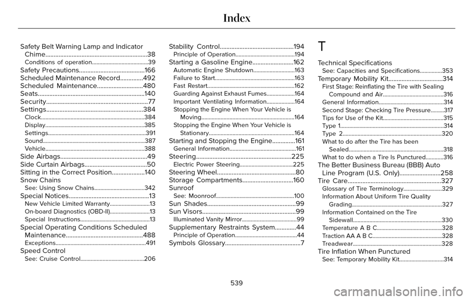
Safety Belt Warning Lamp and IndicatorChime..............................................................38
Conditions of operation......................................39
Safety Precautions........................................166
Scheduled Maintenance Record..............492
Scheduled Maintenance............................480
Seats.................................................................140
Security..............................................................77
Settings...........................................................384
Clock......................................................................384
Display.................................................................\
..385
Settings..................................................................391
Sound...................................................................\
..387
Vehicle..................................................................\
.388
Side Airbags.....................................................49
Side Curtain Airbags......................................50
Sitting in the Correct Position....................140
Snow Chains
See: Using Snow Chains..................................342
Special Notices.................................................13New Vehicle Limited Warranty...........................13
On-board Diagnostics (OBD-II)...........................13
Special Instructions...............................................13
Special Operating Conditions ScheduledMaintenance...............................................488
Exceptions.............................................................491
Speed ControlSee: Cruise Control...........................................206
Stability Control.............................................194Principle of Operation........................................194
Starting a Gasoline Engine.........................162Automatic Engine Shutdown............................163
Failure to Start......................................................163
Fast Restart...........................................................162
Guarding Against Exhaust Fumes...................164
Important Ventilating Information...................164
Stopping the Engine When Your Vehicle is
Moving...............................................................164
Stopping the Engine When Your Vehicle is Stationary..........................................................164
Starting and Stopping the Engine..............161General Information.............................................161
Steering..........................................................225Electric Power Steering....................................225
Steering Wheel................................................80
Storage Compartments...............................160
Sunroof
See: Moonroof.....................................................100
Sun Shades......................................................99
Sun Visors.........................................................99
Illuminated Vanity Mirror.....................................99
Supplementary Restraints System.............44Principle of Operation..........................................44
Symbols Glossary..............................................7
T
Technical SpecificationsSee: Capacities and Specifications...............353
Temporary Mobility Kit.................................314First Stage: Reinflating the Tire with SealingCompound and Air.........................................316
General Information............................................314
Second Stage: Checking Tire Pressure.........317
Tips for Use of the Kit.........................................315
Type 1...................................................................\
...314
Type 2...................................................................\
320
What to do after the Tire has been Sealed................................................................318
What to do when a Tire Is Punctured............316
The Better Business Bureau (BBB) Auto Line Program (U.S. Only).........................258
Tire Care.........................................................327
Glossary of Tire Terminology..........................329
Information About Uniform Tire Quality
Grading.............................................................327
Information Contained on the Tire Sidewall............................................................330
Temperature A B C............................................328
Traction AA A B C...............................................328
Treadwear............................................................328
Tire Inflation When PuncturedSee: Temporary Mobility Kit..............................314
539
Index