front bumper LINCOLN NAVIGATOR 2017 Owners Manual
[x] Cancel search | Manufacturer: LINCOLN, Model Year: 2017, Model line: NAVIGATOR, Model: LINCOLN NAVIGATOR 2017Pages: 532, PDF Size: 3.9 MB
Page 50 of 532
The design and development of the Safety
Canopy included recommended testing
procedures that were developed by a group
of automotive safety experts known as the
Side Airbag Technical Working Group. These
recommended testing procedures help
reduce the risk of injuries related to the
deployment of side airbags (including the
Safety Canopy).
CRASH SENSORS AND AIRBAG
INDICATOR
WARNING
Modifying or adding equipment to the
front end of the vehicle (including
frame, bumper, front end body structure and
tow hooks) may affect the performance of
the airbag system, increasing the risk of
injury. Do not modify the front end of the
vehicle. Your vehicle has a collection of crash and
occupant sensors which provide information
to the restraints control module which
deploys (activates) the front safety belt
pretensioners, driver airbag, passenger
airbag, seat mounted side airbags, and the
Safety Canopy®. Based on the type of crash
(frontal impact, side impact or rollover), the
restraints control module will deploy the
appropriate safety devices.
The restraints control module also monitors
the readiness of the above safety devices
plus the crash and occupant sensors. The
readiness of the safety system is indicated
by a warning indicator light in the instrument
cluster or by a backup tone if the warning
light is not working. See Instrument Cluster
(page 96). Routine maintenance of the
airbag is not required.
A difficulty with the system is indicated by
one or more of the following: The readiness light will not
illuminate immediately after the
ignition is turned on.•
The readiness light will either flash or
stay lit.
• A series of five beeps will be heard. The
tone pattern will repeat periodically until
the problem, the light or both are
repaired.
If any of these things happen, even
intermittently, have the supplemental
restraint system serviced at an authorized
dealer immediately. Unless serviced, the
system may not function properly in the
event of a crash.
47
Navigator (TB5) Canada/United States of America, enUSA, First Printing Supplementary Restraints System
Page 197 of 532
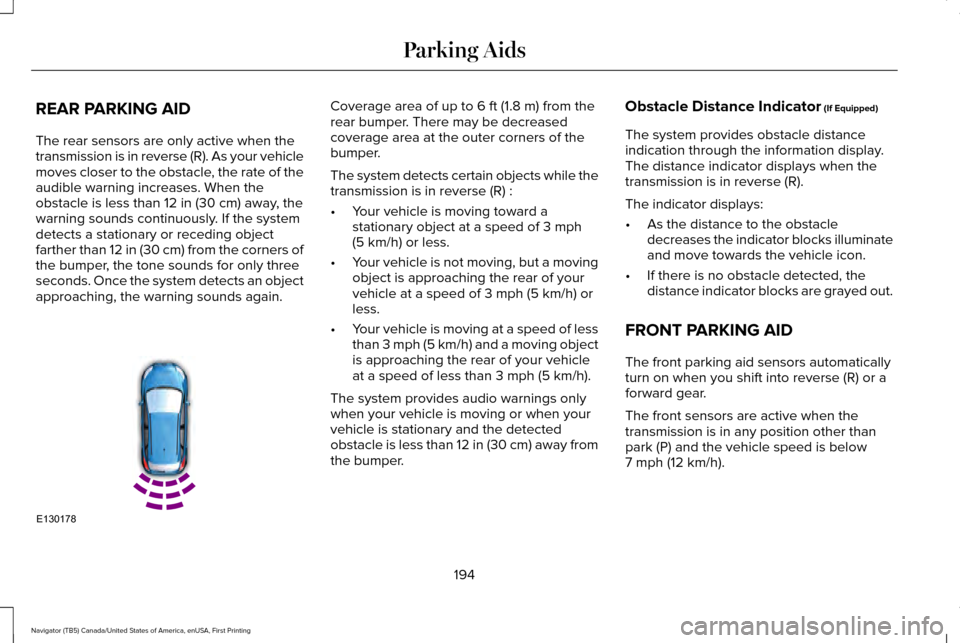
REAR PARKING AID
The rear sensors are only active when the
transmission is in reverse (R). As your vehicle
moves closer to the obstacle, the rate of the
audible warning increases. When the
obstacle is less than 12 in (30 cm) away, the
warning sounds continuously. If the system
detects a stationary or receding object
farther than
12 in (30 cm) from the corners of
the bumper, the tone sounds for only three
seconds. Once the system detects an object
approaching, the warning sounds again. Coverage area of up to
6 ft (1.8 m) from the
rear bumper. There may be decreased
coverage area at the outer corners of the
bumper.
The system detects certain objects while the
transmission is in reverse (R) :
• Your vehicle is moving toward a
stationary object at a speed of
3 mph
(5 km/h) or less.
• Your vehicle is not moving, but a moving
object is approaching the rear of your
vehicle at a speed of
3 mph (5 km/h) or
less.
• Your vehicle is moving at a speed of less
than 3 mph (5 km/h) and a moving object
is approaching the rear of your vehicle
at a speed of less than
3 mph (5 km/h).
The system provides audio warnings only
when your vehicle is moving or when your
vehicle is stationary and the detected
obstacle is less than 12 in (30 cm) away from
the bumper. Obstacle Distance Indicator
(If Equipped)
The system provides obstacle distance
indication through the information display.
The distance indicator displays when the
transmission is in reverse (R).
The indicator displays:
• As the distance to the obstacle
decreases the indicator blocks illuminate
and move towards the vehicle icon.
• If there is no obstacle detected, the
distance indicator blocks are grayed out.
FRONT PARKING AID
The front parking aid sensors automatically
turn on when you shift into reverse (R) or a
forward gear.
The front sensors are active when the
transmission is in any position other than
park (P) and the vehicle speed is below
7 mph (12 km/h)
.
194
Navigator (TB5) Canada/United States of America, enUSA, First Printing Parking AidsE130178
Page 198 of 532
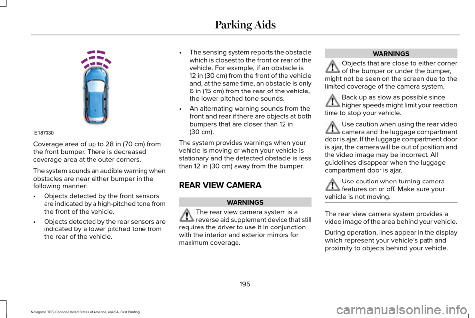
Coverage area of up to 28 in (70 cm) from
the front bumper. There is decreased
coverage area at the outer corners.
The system sounds an audible warning when
obstacles are near either bumper in the
following manner:
• Objects detected by the front sensors
are indicated by a high-pitched tone from
the front of the vehicle.
• Objects detected by the rear sensors are
indicated by a lower pitched tone from
the rear of the vehicle. •
The sensing system reports the obstacle
which is closest to the front or rear of the
vehicle. For example, if an obstacle is
12 in (30 cm) from the front of the vehicle
and, at the same time, an obstacle is only
6 in (15 cm)
from the rear of the vehicle,
the lower pitched tone sounds.
• An alternating warning sounds from the
front and rear if there are objects at both
bumpers that are closer than
12 in
(30 cm).
The system provides warnings when your
vehicle is moving or when your vehicle is
stationary and the detected obstacle is less
than
12 in (30 cm) away from the bumper.
REAR VIEW CAMERA WARNINGS
The rear view camera system is a
reverse aid supplement device that still
requires the driver to use it in conjunction
with the interior and exterior mirrors for
maximum coverage. WARNINGS
Objects that are close to either corner
of the bumper or under the bumper,
might not be seen on the screen due to the
limited coverage of the camera system. Back up as slow as possible since
higher speeds might limit your reaction
time to stop your vehicle. Use caution when using the rear video
camera and the luggage compartment
door is ajar. If the luggage compartment door
is ajar, the camera will be out of position and
the video image may be incorrect. All
guidelines disappear when the luggage
compartment door is ajar. Use caution when turning camera
features on or off. Make sure your
vehicle is not moving. The rear view camera system provides a
video image of the area behind your vehicle.
During operation, lines appear in the display
which represent your vehicle
’s path and
proximity to objects behind your vehicle.
195
Navigator (TB5) Canada/United States of America, enUSA, First Printing Parking AidsE187330
Page 208 of 532
The system uses radar sensors which are
located behind the bumper fascia on each
side of your vehicle. Do not allow these areas
to become obstructed by mud, snow or
bumper stickers, as this can cause degraded
system performance.
If the system detects a degraded
performance condition, a blocked sensor
warning or low visibility warning will appear
in the information display and the alert
indicator illuminates in the appropriate
mirror(s). The information display warning
can be cleared but the alert indicator remains
illuminated.When the blockage is removed, the system
can be reset in two ways: 1) when at least
two objects are detected while driving, or 2)
turn the ignition key from on to off, then back
on. If the blockage is still present after the
key cycle, the system senses again that it is
blocked after driving in traffic. Reasons for messages being displayed
Clean the fascia area in front of the radar or remove the obstruction.
The radar surface is dirty or obstructed
Drive normally in traffic for a few minutes to allow the radar to detect\
passing vehicles so it can clear the blocked state.
The radar surface is not dirty or obstructed
No action required. The system automatically resets to an unblockedstate once the rainfall/snowfall rate decreases or stops. Do not use the Blind Spot Information System or Cross Traffic Alert in these conditions.
Heavy rainfall/snowfall interferes with the radar signals
System Limitations
The Blind Spot Information and Cross Traffic
Alert systems do have their limitations;
situations such as severe weather conditions
or debris build-up on the sensor area may
limit vehicle detection. 205
Navigator (TB5) Canada/United States of America, enUSA, First Printing Driving Aids
Page 225 of 532
The standard integrated hitch has two ratings
depending on mode of operation:
•
Weight-carrying mode requires a draw
bar and hitch ball. The draw bar supports
all the vertical tongue load of the trailer. •
Weight-distributing mode requires an
aftermarket weight-distributing system,
which includes draw bar, hitch ball, spring
bars and snap-up brackets. This system
distributes the vertical tongue load of the
trailer between the truck and the trailer. Maximum Tongue Weight
Maximum Trailer Weight
Mode
600 lb (272 kg)
6000 lb (2722 kg)
Weight carrying
900 lb (408 kg)
9000 lb (4082 kg)
Weight distributing
Note: These are hitch ratings only. Actual
vehicle ratings are dependent on engine,
transmission and axle combinations. Weight-distributing Hitch - Vehicles without
Automatic Leveling Suspension WARNING
Do not adjust a weight-distributing
hitch to any position where the rear
bumper of the vehicle is higher than it was
before attaching the trailer. Doing so will
defeat the function of the weight-distributing
hitch, which may cause unpredictable
handling, and could result in serious personal
injury. When hooking-up a trailer using a
weight-distributing hitch, always use the
following procedure:
1. Park the loaded vehicle, without the
trailer, on a level surface.
2. Measure the height to the top of your vehicle's front wheel opening on the
fender. This is H1.
3. Attach the loaded trailer to your vehicle without the weight-distributing bars
connected.
4. Measure the height to the top of your vehicle's front wheel opening on the
fender a second time. This is H2.
222
Navigator (TB5) Canada/United States of America, enUSA, First Printing Towing
Page 226 of 532
5. Install and adjust the tension in the
weight-distributing bars so that the height
of your vehicle's front wheel opening on
the fender is approximately half the way
down from H2, toward H1.
6. Check that the trailer is level or slightly nose down toward your vehicle. If not,
adjust the ball height accordingly and
repeat Steps 2-6.
When the trailer is level or slightly nose down
toward the vehicle:
• Lock the bar tension adjuster in place.
• Check that the trailer tongue securely
attaches and locks onto the hitch.
• Install safety chains, lighting, and trailer
brake controls as required by law or the
trailer manufacturer. Weight-distributing Hitch - Vehicles with
Automatic Leveling Suspension WARNING
Do not adjust a weight-distributing
hitch to any position where the rear
bumper of the vehicle is higher than it was
before attaching the trailer. Doing so will
defeat the function of the weight-distributing
hitch, which may cause unpredictable
handling, and could result in serious personal
injury. Note:
If you do not move the loaded vehicle
for approximately 12 hours, the leveling
system may bleed down to a lower height.
This can be especially apparent if you leave
a trailer attached to the parked vehicle for
long periods. You must drive your vehicle in
order to re-level the suspension.
When hooking-up a trailer using a
weight-distributing hitch, always use the
following procedure: 1. Load the interior of the vehicle to a
weight similar to that which you intend
to carry when towing. This includes
things such as passenger weight and
cargo.
2. Drive the vehicle for approximately 2 miles (3 kilometers) to re-level the
suspension.
3. Park the loaded vehicle, without the trailer, on a level surface.
4. Measure the height to the top of your vehicle's front wheel opening on the
fender. This is H1.
5. Attach the loaded trailer to your vehicle without the weight-distributing bars
connected.
6. Make sure you securely attach and lock the trailer tongue to the hitch.
7. Install safety chains, lighting, and trailer brake controls as required by law or the
trailer manufacturer.
8. Drive the vehicle and trailer at 20–25 mph (32–40 km/h) for approximately 2
miles (3 kilometers) to re-level the
suspension.
223
Navigator (TB5) Canada/United States of America, enUSA, First Printing Towing
Page 227 of 532
9. Park your vehicle and trailer on a level
surface.
10. Measure the height to the top of your vehicle's front wheel opening on the
fender a second time. This is H2.
11. Install and adjust the tension in the weight-distributing bars so that the
height of your vehicle's front wheel
opening on the fender is approximately
half the way down from H2, toward H1.
12. Check that the trailer is level or slightly
nose down toward your vehicle. If not,
remove the trailer, adjust the ball height
accordingly and repeat Steps 5-11.
When the trailer is level or slightly nose down
toward the vehicle:
• Lock the bar tension adjuster in place.
• Check that the trailer tongue securely
attaches and locks onto the hitch.
• Install safety chains, lighting, and trailer
brake controls as required by law or the
trailer manufacturer. Safety Chains
Note:
Never attach safety chains to the
bumper.
Always connect the safety chains to the hook
retainers of your vehicle hitch.
To connect the trailer’ s safety chains, cross
them under the trailer tongue and allow
enough slack for turning tight corners. Do
not allow the chains to drag on the ground.
Trailer Brakes (If Equipped) WARNING
Do not connect a trailer's hydraulic
brake system directly to your vehicle's
brake system. Your vehicle may not have
enough braking power and your chances of
having a collision greatly increase. Electric brakes and manual, automatic or
surge-type trailer brakes are safe if you install
them properly and adjust them to the
manufacturer's specifications. The trailer
brakes must meet local and federal
regulations.The rating for the tow vehicle's braking
system operation is at the gross vehicle
weight rating, not the gross combined
weight rating.
Separate functioning brake systems are
required for safe control of towed vehicles
and trailers weighing more than 1500
pounds (680 kilograms) when loaded.
Trailer Lamps
WARNING
Never connect any trailer lamp wiring
to the vehicle's tail lamp wiring; this
may damage the electrical system resulting
in fire. Contact your authorized dealer as
soon as possible for assistance in proper
trailer tow wiring installation. Additional
electrical equipment may be required. Trailer lamps are required on most towed
vehicles. Make sure all running lights, brake
lights, turn signals and hazard lights are
working.
224
Navigator (TB5) Canada/United States of America, enUSA, First Printing Towing
Page 229 of 532
Your vehicle may be equipped with a
temporary or conventional spare tire. A
“temporary” spare tire is different in size
(diameter or width), tread-type (All-Season
or All-Terrain) or is from a different
manufacturer than the road tires on your
vehicle. Consult information on the tire label
or Safety Compliance label for limitations
when using.
Launching or Retrieving a Boat or
Personal Watercraft (PWC)
Note:
Disconnect the wiring to the trailer
before backing the trailer into the water.
Note: Reconnect the wiring to the trailer
after
removing the trailer from the water.
When backing down a ramp during boat
launching or retrieval:
• Do not allow the static water level to rise
above the bottom edge of the rear
bumper.
• Do not allow waves to break higher than
6 inches (15 centimeters) above the
bottom edge of the rear bumper. Exceeding these limits may allow water to
enter vehicle components:
•
Causing internal damage to the
components.
• Affecting driveability, emissions, and
reliability.
Replace the rear axle lubricant anytime the
rear axle has been submerged in water.
Water may have contaminated the rear axle
lubricant, which is not normally checked or
changed unless a leak is suspected or other
axle repair is required.
TOWING POINTS WARNINGS
Using recovery hooks is dangerous
and should only be done by a person
familiar with proper vehicle recovery safety
practices. Improper use of recovery hooks
may cause hook failure or separation from
the vehicle and could result in serious injury
or death. WARNINGS
Always slowly remove the slack from
the recovery strap prior to pulling.
Failure to do so can introduce significantly
higher loads which can cause the recovery
hooks to break off, or the recovery strap to
fail which can cause serious injury or death. Never link two straps together with a
clevis pin. These heavy metal objects
could become projectiles if the strap breaks
and can cause serious injury or death. Your vehicle comes equipped with
frame-mounted front recovery hooks. These
hooks should never have a load applied to
them greater than the gross vehicle weight
rating of your vehicle.
Before using recovery hooks:
•
Make sure all attaching points are secure
and capable of withstanding the applied
load.
• Never use chains, cables or tow straps
with metal hook ends.
226
Navigator (TB5) Canada/United States of America, enUSA, First Printing Towing
Page 315 of 532
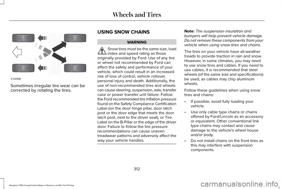
Sometimes irregular tire wear can be
corrected by rotating the tires.
USING SNOW CHAINS WARNING
Snow tires must be the same size, load
index and speed rating as those
originally provided by Ford. Use of any tire
or wheel not recommended by Ford can
affect the safety and performance of your
vehicle, which could result in an increased
risk of loss of control, vehicle rollover,
personal injury and death. Additionally, the
use of non-recommended tires and wheels
can cause steering, suspension, axle, transfer
case or power transfer unit failure. Follow
the Ford recommended tire inflation pressure
found on the Safety Compliance Certification
Label (on the door hinge pillar, door latch
post or the door edge that meets the door
latch post, next to the driver seat), or Tire
Label on the B-Pillar or the edge of the driver
door. Failure to follow the tire pressure
recommendations can cause uneven
treadwear patterns and adversely affect the
way your vehicle handles. Note:
The suspension insulation and
bumpers will help prevent vehicle damage.
Do not remove these components from your
vehicle when using snow tires and chains.
The tires on your vehicle have all-weather
treads to provide traction in rain and snow.
However, in some climates, you may need
to use snow tires and cables. If you need to
use cables, it is recommended that steel
wheels (of the same size and specifications)
be used, as cables may chip aluminum
wheels.
Follow these guidelines when using snow
tires and chains:
• If possible, avoid fully loading your
vehicle.
• Use only cable type chains or chains
offered by Ford/Lincoln as an accessory
or equivalent. Other conventional link
type chains may contact and cause
damage to the vehicle's wheel house
and/or body.
• Do not install chains on the front tires as
this may interfere with suspension
components.
312
Navigator (TB5) Canada/United States of America, enUSA, First Printing Wheels and TiresE142548