clock LINCOLN NAVIGATOR 2020 Owners Manual
[x] Cancel search | Manufacturer: LINCOLN, Model Year: 2020, Model line: NAVIGATOR, Model: LINCOLN NAVIGATOR 2020Pages: 622, PDF Size: 6.47 MB
Page 47 of 622
Note:
The child restraint must rest tightly
against the vehicle seat upon which it is
installed. It may be necessary to lift or
remove the head restraint. See Seats (page
172).
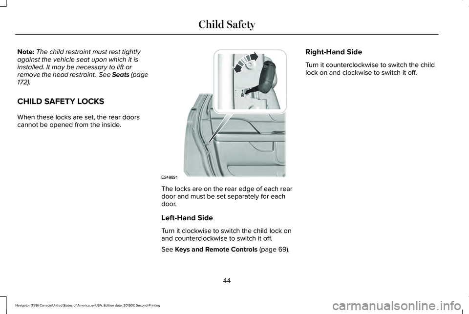
CHILD SAFETY LOCKS
When these locks are set, the rear doors
cannot be opened from the inside. The locks are on the rear edge of each rear
door and must be set separately for each
door.
Left-Hand Side
Turn it clockwise to switch the child lock on
and counterclockwise to switch it off.
See
Keys and Remote Controls (page 69).Right-Hand Side
Turn it counterclockwise to switch the child
lock on and clockwise to switch it off.
44
Navigator (TB9) Canada/United States of America, enUSA, Edition date: 201907, Second-Printing Child SafetyE249891
Page 320 of 622
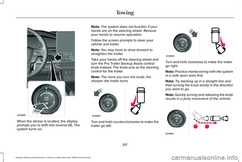
When the sticker is located, the display
prompts you to shift into reverse (R). The
system turns on. Note:
The system does not function if your
hands are on the steering wheel. Remove
your hands to resume operation.
Follow the screen prompts to steer your
vehicle and trailer.
Note: You may have to drive forward to
straighten the trailer.
Take your hands off the steering wheel and
turn the Pro Trailer Backup Assist control
knob instead. The knob acts as the steering
control for the trailer.
Note: The more you turn the knob, the
sharper the trailer turns. Turn and hold counterclockwise to make the
trailer go left. Turn and hold clockwise to make the trailer
go right.
Note:
Practice maneuvering with the system
in a safe open area first.
Note: Try backing up in a straight line and
then turning the knob slowly in the direction
you want to go.
Note: Quickly turning and releasing the knob
results in a jerky movement of the vehicle. 317
Navigator (TB9) Canada/United States of America, enUSA, Edition date: 201907, Second-Printing TowingE246984 E246992 E246991 E246993
Page 381 of 622
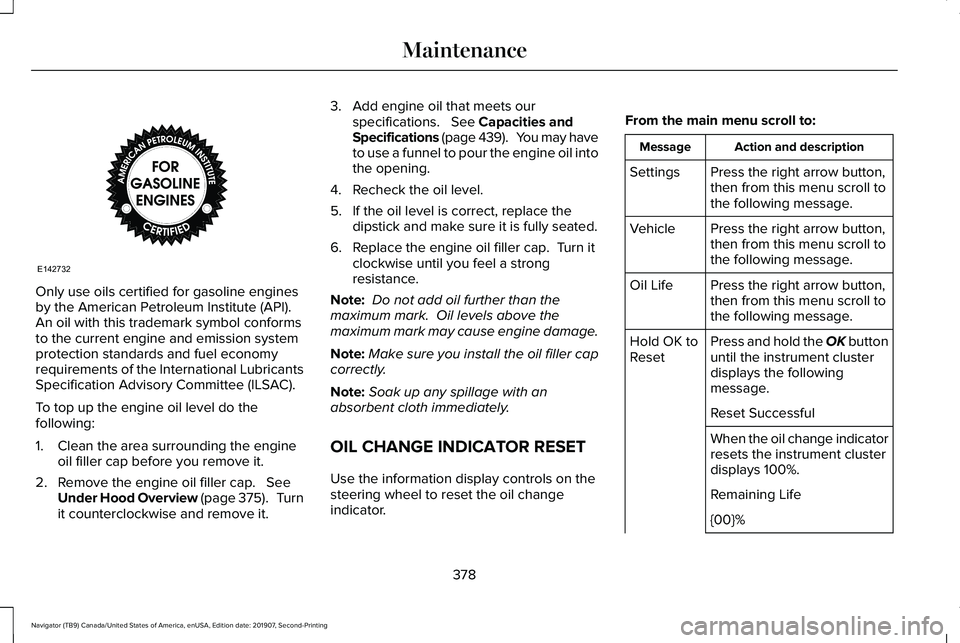
Only use oils certified for gasoline engines
by the American Petroleum Institute (API).
An oil with this trademark symbol conforms
to the current engine and emission system
protection standards and fuel economy
requirements of the International Lubricants
Specification Advisory Committee (ILSAC).
To top up the engine oil level do the
following:
1. Clean the area surrounding the engine
oil filler cap before you remove it.
2. Remove the engine oil filler cap. See
Under Hood Overview (page 375). Turn
it counterclockwise and remove it. 3. Add engine oil that meets our
specifications.
See Capacities and
Specifications (page 439). You may have
to use a funnel to pour the engine oil into
the opening.
4. Recheck the oil level.
5. If the oil level is correct, replace the dipstick and make sure it is fully seated.
6. Replace the engine oil filler cap. Turn it clockwise until you feel a strong
resistance.
Note: Do not add oil further than the
maximum mark. Oil levels above the
maximum mark may cause engine damage.
Note: Make sure you install the oil filler cap
correctly.
Note: Soak up any spillage with an
absorbent cloth immediately.
OIL CHANGE INDICATOR RESET
Use the information display controls on the
steering wheel to reset the oil change
indicator. From the main menu scroll to: Action and description
Message
Press the right arrow button,
then from this menu scroll to
the following message.
Settings
Press the right arrow button,
then from this menu scroll to
the following message.
Vehicle
Press the right arrow button,
then from this menu scroll to
the following message.
Oil Life
Press and hold the OK button
until the instrument cluster
displays the following
message.
Hold OK to
Reset
Reset Successful
When the oil change indicator
resets the instrument cluster
displays 100%.
Remaining Life
{00}%
378
Navigator (TB9) Canada/United States of America, enUSA, Edition date: 201907, Second-Printing MaintenanceE142732
Page 384 of 622
Note:
Do not use stop leak pellets, cooling
system sealants, or non-specified additives
as they can cause damage to the engine
cooling or heating systems. Resulting
component damage may not be covered by
the vehicle Warranty.
It is very important to use prediluted coolant
approved to the correct specification in order
to avoid plugging the small passageways in
the engine cooling system. See Capacities
and Specifications (page 435). Do not mix
different colors or types of coolant in your
vehicle. Mixing of engine coolants or using
an incorrect coolant may harm the engine or
cooling system components and may not be
covered by the vehicle Warranty.
Note: If prediluted coolant is not available,
use the approved concentrated coolant
diluting it to 50/50 with distilled water.
See
Capacities and Specifications (page 435).
Using water that has not been deionised
may contribute to deposit formation,
corrosion and plugging of the small cooling
system passageways. Note:
Coolants marketed for all makes and
models may not be approved to our
specifications and may cause damage to
the cooling system. Resulting component
damage may not be covered by the vehicle
Warranty.
If the coolant level is at or below the
minimum mark, add prediluted coolant
immediately.
To top up the coolant level do the following:
1. Unscrew the cap slowly. Any pressure escapes as you unscrew the cap.
2. Add prediluted coolant approved to the correct specification. See Capacities and
Specifications
(page 435).
3. Add enough prediluted coolant to reach
the correct level.
4. Replace the coolant reservoir cap. Turn the cap clockwise until it contacts the
hard stop.
5. Check the coolant level in the coolant reservoir the next few times you drive
your vehicle. If necessary, add enough
prediluted engine coolant to bring the
coolant level to the correct level. If you have to add more than
1.1 qt (1 L) of
engine coolant per month, have your vehicle
checked as soon as possible. Operating an
engine with a low level of coolant can result
in engine overheating and possible engine
damage.
In case of emergency, you can add a large
amount of water without engine coolant in
order to reach a vehicle service location. In
this instance, qualified personnel:
1. Must drain the cooling system.
2. Chemically clean the coolant system.
3. Refill with engine coolant as soon as possible.
Water alone, without engine coolant, can
cause engine damage from corrosion,
overheating or freezing.
Do not use the following as a coolant
substitute:
• Alcohol.
• Methanol.
• Brine.
• Any coolant mixed with alcohol or
methanol antifreeze.
381
Navigator (TB9) Canada/United States of America, enUSA, Edition date: 201907, Second-Printing Maintenance
Page 391 of 622
If you see any corrosion on the battery or
terminals, remove the cables from the
terminals and clean with a wire brush. You
can neutralize the acid with a solution of
baking soda and water.
Because your vehicle
’s engine is
electronically controlled by a computer, some
control conditions are maintained by power
from the battery. When the battery is
disconnected or a new battery is installed,
the engine must relearn its idle and fuel trim
strategy for optimum driveability and
performance. Flexible fuel vehicles (FFV)
must also relearn the ethanol content of the
fuel for optimum driveability and
performance.
To restore the settings, do the following:
1. Apply the parking brake.
2. Shift into park (P) or neutral (N).
3. Switch off all accessories.
4. Press the brake pedal and start your vehicle. 5. Run the engine until it reaches normal
operating temperature. While the engine
is warming up, complete the following:
Reset the clock. Reset the power
windows bounce-back feature. See
Windows and Mirrors (page 118). Reset
the radio station presets. See Audio
System (page 460).
6. Allow the engine to idle for at least one minute.
7. Drive the vehicle at least 10 mi (16 km) to
completely relearn the idle trim and fuel
trim strategy.
Note: If you do not allow the engine to
relearn the idle and fuel trim strategy, the
idle quality of your vehicle may be adversely
affected until the engine computer
eventually relearns the idle trim and fuel trim
strategy.
Note: For flexible fuel vehicles, if you are
operating on E85, you may experience poor
starts or an inability to start the engine and
driveability problems until the fuel trim and
ethanol content have been relearned. Make sure that you dispose of old batteries
in an environmentally friendly way. Seek
advice from your local authority about
recycling old batteries.
If storing your vehicle for more than 30 days
without recharging the battery, we
recommend that you disconnect the negative
battery cable to maintain battery charge for
quick starting.
Battery Management System
(If Equipped)
The battery management system monitors
battery conditions and takes actions to
extend battery life. If excessive battery drain
is detected, the system temporarily disables
some electrical systems to protect the
battery.
Systems included are:
• Heated rear window.
• Heated seats.
• Climate control.
• Heated steering wheel.
• Audio unit.
• Navigation system.
388
Navigator (TB9) Canada/United States of America, enUSA, Edition date: 201907, Second-Printing Maintenance
Page 393 of 622
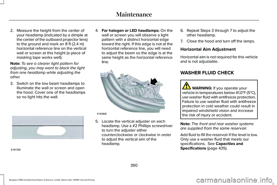
2. Measure the height from the center of
your headlamp (indicated by a dimple at
the center of the outboard projector lens)
to the ground and mark an 8 ft (2.4 m)
horizontal reference line on the vertical
wall or screen at this height (a piece of
masking tape works well).
Note: To see a clearer light pattern for
adjusting, you may want to block the light
from one headlamp while adjusting the
other.
3. Switch on the low beam headlamps to illuminate the wall or screen and open
the hood. Cover one of the headlamps
so no light hits the wall. 4.
For halogen or LED headlamps: On the
wall or screen you will observe a light
pattern with a distinct horizontal edge
toward the right. If this edge is not at the
horizontal reference line, you will need
to adjust the beam so the edge is at the
same height as the horizontal reference
line. 5. Locate the vertical adjuster on each
headlamp. Use a #2 Phillips screwdriver
to turn the adjuster either
counterclockwise or clockwise in order
to adjust the vertical aim of the
headlamp. 6. Repeat Steps 3 through 7 to adjust the
other headlamp.
7. Close the hood and turn off the lamps.
Horizontal Aim Adjustment
Horizontal aim is not required for this vehicle
and is not adjustable.
WASHER FLUID CHECK WARNING:
If you operate your
vehicle in temperatures below 41.0°F (5°C),
use washer fluid with antifreeze protection.
Failure to use washer fluid with antifreeze
protection in cold weather could result in
impaired windshield vision and increase
the risk of injury or accident.
Note: The front and rear washer systems
are supplied from the same reservoir.
Add fluid to fill the reservoir if the level is low.
Only use a washer fluid that meets our
specifications.
See Capacities and
Specifications (page 435).
390
Navigator (TB9) Canada/United States of America, enUSA, Edition date: 201907, Second-Printing MaintenanceE167358 E163806
Page 432 of 622
WARNING: Switch off the running
boards before jacking or placing any object
under your vehicle. Never place your hand
between the extended running board and
your vehicle. A moving running board may
cause injury. WARNING: Only use the spare wheel
carrier to stow the wheel provided with
your vehicle. Other wheel sizes could
cause the spare wheel carrier to fail if it
does not fit securely or is too heavy. 1.
Park the vehicle on firm, level ground and
activate the hazard flashers. 2. Apply the parking brake, place the
transmission in park (P) and switch the
ignition off.
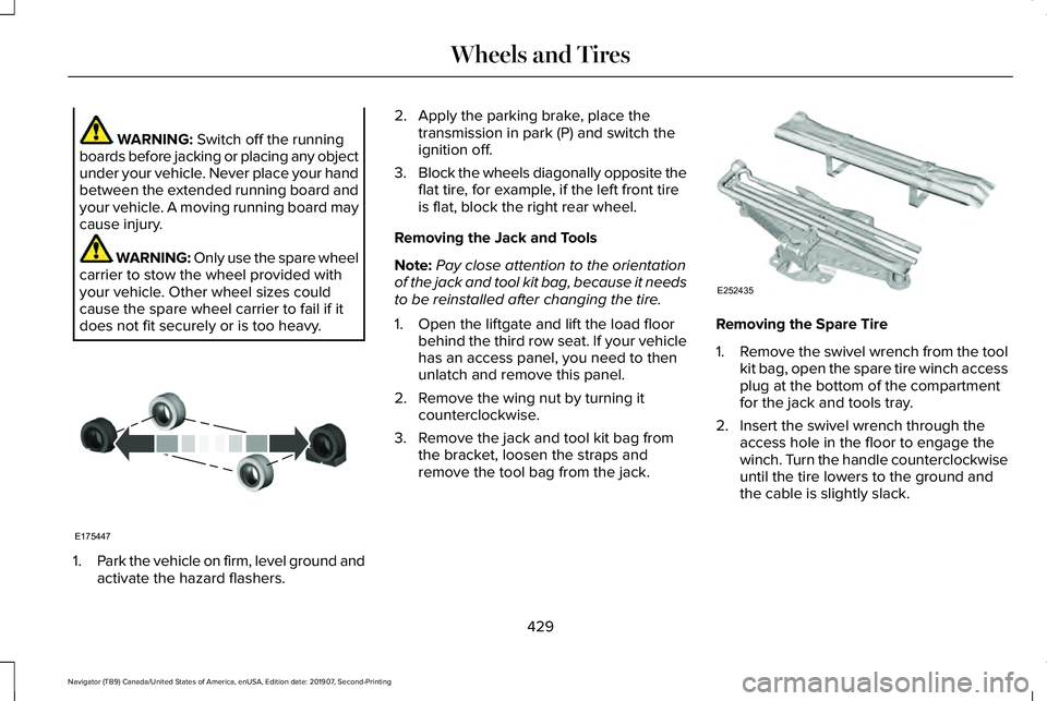
3. Block the wheels diagonally opposite the
flat tire, for example, if the left front tire
is flat, block the right rear wheel.
Removing the Jack and Tools
Note: Pay close attention to the orientation
of the jack and tool kit bag, because it needs
to be reinstalled after changing the tire.
1. Open the liftgate and lift the load floor behind the third row seat. If your vehicle
has an access panel, you need to then
unlatch and remove this panel.
2. Remove the wing nut by turning it counterclockwise.
3. Remove the jack and tool kit bag from the bracket, loosen the straps and
remove the tool bag from the jack. Removing the Spare Tire
1.
Remove the swivel wrench from the tool
kit bag, open the spare tire winch access
plug at the bottom of the compartment
for the jack and tools tray.
2. Insert the swivel wrench through the access hole in the floor to engage the
winch. Turn the handle counterclockwise
until the tire lowers to the ground and
the cable is slightly slack.
429
Navigator (TB9) Canada/United States of America, enUSA, Edition date: 201907, Second-Printing Wheels and TiresE175447 E252435
Page 433 of 622
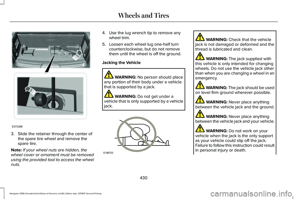
3. Slide the retainer through the center of
the spare tire wheel and remove the
spare tire.
Note: If your wheel nuts are hidden, the
wheel cover or ornament must be removed
using the provided tool to access the wheel
nuts. 4. Use the lug wrench tip to remove any
wheel trim.
5. Loosen each wheel lug one-half turn counterclockwise, but do not remove
them until the wheel is off the ground.
Jacking the Vehicle WARNING: No person should place
any portion of their body under a vehicle
that is supported by a jack. WARNING:
Do not get under a
vehicle that is only supported by a vehicle
jack. WARNING:
Check that the vehicle
jack is not damaged or deformed and the
thread is lubricated and clean. WARNING:
The jack supplied with
this vehicle is only intended for changing
wheels. Do not use the vehicle jack other
than when you are changing a wheel in an
emergency. WARNING: The jack should be used
on level firm ground wherever possible. WARNING:
Never place anything
between the vehicle jack and the ground. WARNING:
Never place anything
between the vehicle jack and your vehicle. WARNING:
Do not work on your
vehicle when the jack is the only support
as your vehicle could slip off the jack.
Failure to follow this instruction could result
in personal injury or death.
430
Navigator (TB9) Canada/United States of America, enUSA, Edition date: 201907, Second-Printing Wheels and TiresE273399 E166722
Page 434 of 622
WARNING: It is recommended that
the wheels of the vehicle be chocked, and
that no person should remain in a vehicle
that is being jacked. WARNING:
Failure to follow these
guidelines could result in an increased risk
of loss of vehicle control, injury or death.
Note: The jack does not require
maintenance or additional lubrication over
the service life of your vehicle.
Note: Both the front and rear jacking points
are on the frame rails. The correct locations
on the frame rails are marked with an arrow
punched into the frame rail. Jack at the
specified locations to avoid damaging your
vehicle.
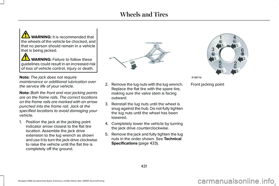
1. Position the jack at the jacking point indicator arrow closest to the flat tire
location. Assemble the jack drive
extension to the lug wrench as shown
and use it to turn the jack drive clockwise
to raise the vehicle until the flat tire is
completely off the ground. 2.
Remove the lug nuts with the lug wrench.
Replace the flat tire with the spare tire,
making sure the valve stem is facing
outward.
3. Reinstall the lug nuts until the wheel is snug against the hub. Do not fully tighten
the lug nuts until the wheel has been
lowered.
4. Completely lower the vehicle by turning the jack drive counterclockwise.
5. Remove the jack and fully tighten the lug
nuts in the order shown.
See Technical
Specifications (page 433). Front jacking point
431
Navigator (TB9) Canada/United States of America, enUSA, Edition date: 201907, Second-Printing Wheels and TiresE325278 E166719
1
3
5 4
6
2
Page 435 of 622
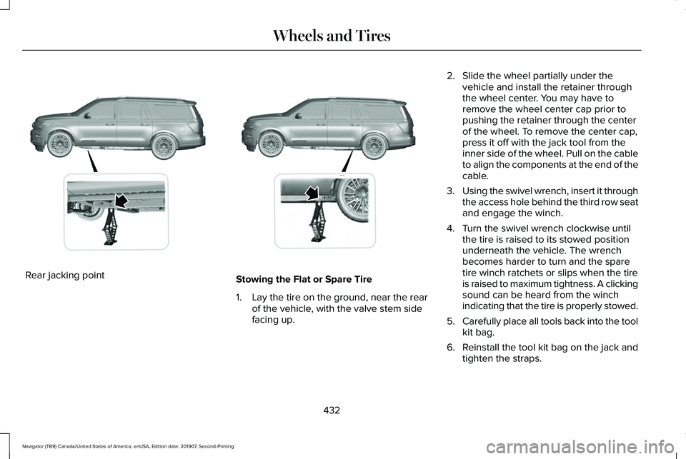
Rear jacking point
Stowing the Flat or Spare Tire
1.
Lay the tire on the ground, near the rear
of the vehicle, with the valve stem side
facing up. 2. Slide the wheel partially under the
vehicle and install the retainer through
the wheel center. You may have to
remove the wheel center cap prior to
pushing the retainer through the center
of the wheel. To remove the center cap,
press it off with the jack tool from the
inner side of the wheel. Pull on the cable
to align the components at the end of the
cable.
3. Using the swivel wrench, insert it through
the access hole behind the third row seat
and engage the winch.
4. Turn the swivel wrench clockwise until the tire is raised to its stowed position
underneath the vehicle. The wrench
becomes harder to turn and the spare
tire winch ratchets or slips when the tire
is raised to maximum tightness. A clicking
sound can be heard from the winch
indicating that the tire is properly stowed.
5. Carefully place all tools back into the tool
kit bag.
6. Reinstall the tool kit bag on the jack and
tighten the straps.
432
Navigator (TB9) Canada/United States of America, enUSA, Edition date: 201907, Second-Printing Wheels and TiresE325274 E325281