brake LINCOLN TOWN CAR 2002 Owners Manual
[x] Cancel search | Manufacturer: LINCOLN, Model Year: 2002, Model line: TOWN CAR, Model: LINCOLN TOWN CAR 2002Pages: 248, PDF Size: 1.9 MB
Page 2 of 248
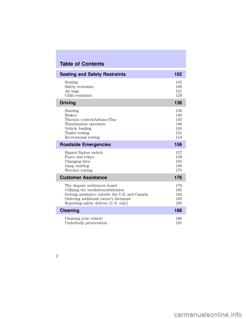
Seating and Safety Restraints 102
Seating 102
Safety restraints 106
Air bags 121
Child restraints 128
Driving 136
Starting 136
Brakes 140
Traction control/AdvanceTrac 143
Transmission operation 146
Vehicle loading 150
Trailer towing 151
Recreational towing 154
Roadside Emergencies 156
Hazard flasher switch 157
Fuses and relays 158
Changing tires 165
Jump starting 169
Wrecker towing 175
Customer Assistance 176
The dispute settlement board 179
Utilizing the mediation/arbitration 182
Getting assistance outside the U.S. and Canada 182
Ordering additional owner's literature 183
Reporting safety defects (U.S. only) 185
Cleaning 186
Cleaning your vehicle 186
Underbody preservation 191
Table of Contents
2
Page 8 of 248
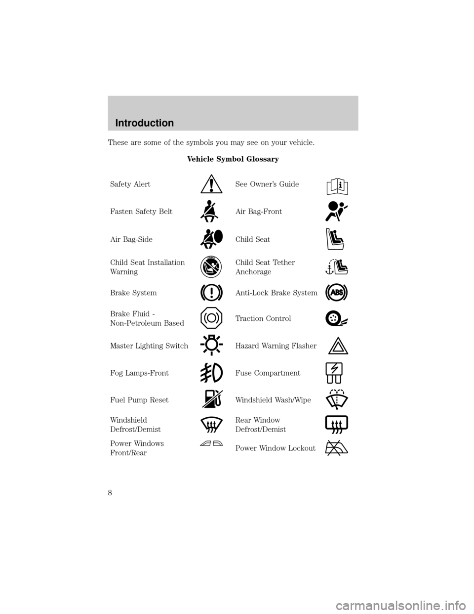
These are some of the symbols you may see on your vehicle.
Vehicle Symbol Glossary
Safety Alert
See Owner's Guide
Fasten Safety BeltAir Bag-Front
Air Bag-SideChild Seat
Child Seat Installation
WarningChild Seat Tether
Anchorage
Brake SystemAnti-Lock Brake System
Brake Fluid -
Non-Petroleum BasedTraction Control
Master Lighting SwitchHazard Warning Flasher
Fog Lamps-FrontFuse Compartment
Fuel Pump ResetWindshield Wash/Wipe
Windshield
Defrost/DemistRear Window
Defrost/Demist
Power Windows
Front/RearPower Window Lockout
Introduction
8
Page 10 of 248
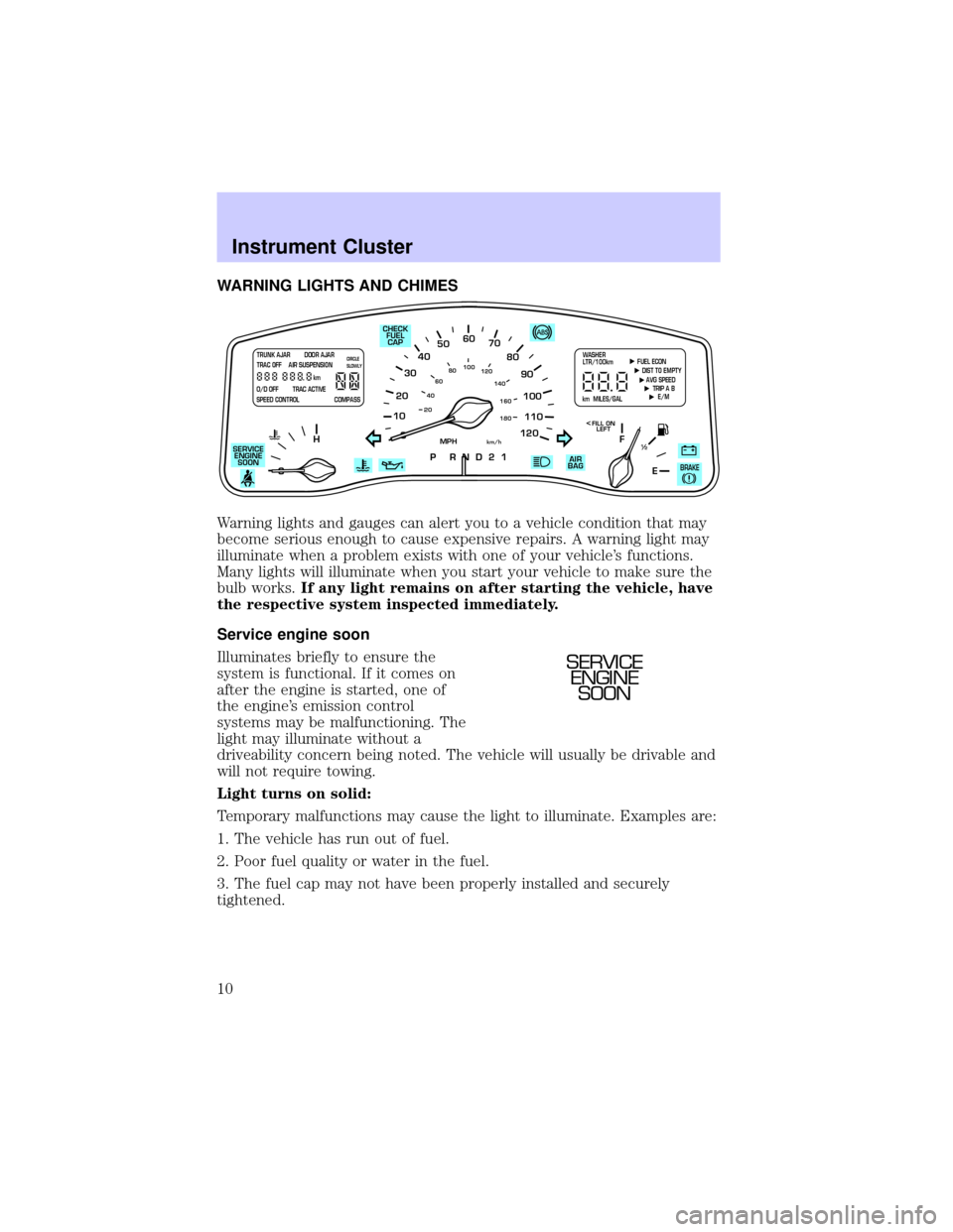
WARNING LIGHTS AND CHIMES
Warning lights and gauges can alert you to a vehicle condition that may
become serious enough to cause expensive repairs. A warning light may
illuminate when a problem exists with one of your vehicle's functions.
Many lights will illuminate when you start your vehicle to make sure the
bulb works.If any light remains on after starting the vehicle, have
the respective system inspected immediately.
Service engine soon
Illuminates briefly to ensure the
system is functional. If it comes on
after the engine is started, one of
the engine's emission control
systems may be malfunctioning. The
light may illuminate without a
driveability concern being noted. The vehicle will usually be drivable and
will not require towing.
Light turns on solid:
Temporary malfunctions may cause the light to illuminate. Examples are:
1. The vehicle has run out of fuel.
2. Poor fuel quality or water in the fuel.
3. The fuel cap may not have been properly installed and securely
tightened.
10
2030405060
70
80
90
100
120206080
40100
120
160 140
180
P R N D 2 1
MPHkm/h
110
HF
E1
2
FILL ON
LEFT<
AIR
BAG CHECK
FUEL
CAP
SERVICE
ENGINE
SOON
TRUNK AJAR DOOR AJAR
TRAC OFF AIR SUSPENSION
O/D OFF TRAC ACTIVE
SPEED CONTROL COMPASSkmCIRCLE
SLOWLY FUEL ECON
DIST TO EMPTY
AVG SPEED
TRIP A B
E/M
km MILES/GALWASHER
LTR/100km
BRAKE
SERVICE
ENGINE
SOON
Instrument Cluster
10
Page 12 of 248
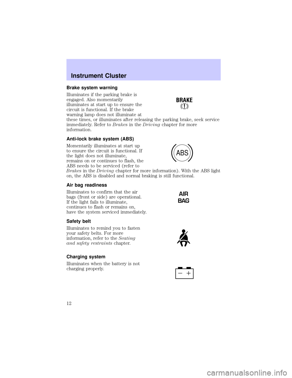
Brake system warning
Illuminates if the parking brake is
engaged. Also momentarily
illuminates at start up to ensure the
circuit is functional. If the brake
warning lamp does not illuminate at
these times, or illuminates after releasing the parking brake, seek service
immediately. Refer toBrakesin theDrivingchapter for more
information.
Anti-lock brake system (ABS)
Momentarily illuminates at start up
to ensure the circuit is functional. If
the light does not illuminate,
remains on or continues to flash, the
ABS needs to be serviced (refer to
Brakesin theDrivingchapter for more information). With the ABS light
on, the ABS is disabled and normal braking is still functional.
Air bag readiness
Illuminates to confirm that the air
bags (front or side) are operational.
If the light fails to illuminate,
continues to flash or remains on,
have the system serviced immediately.
Safety belt
Illuminates to remind you to fasten
your safety belts. For more
information, refer to theSeating
and safety restraintschapter.
Charging system
Illuminates when the battery is not
charging properly.
!
BRAKE
ABS
AIR
BAG
Instrument Cluster
12
Page 17 of 248
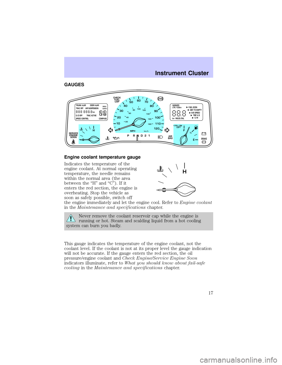
GAUGES
Engine coolant temperature gauge
Indicates the temperature of the
engine coolant. At normal operating
temperature, the needle remains
within the normal area (the area
between the ªHº and ªCº). If it
enters the red section, the engine is
overheating. Stop the vehicle as
soon as safely possible, switch off
the engine immediately and let the engine cool. Refer toEngine coolant
in theMaintenance and specificationschapter.
Never remove the coolant reservoir cap while the engine is
running or hot. Steam and scalding liquid from a hot cooling
system can burn you badly.
This gauge indicates the temperature of the engine coolant, not the
coolant level. If the coolant is not at its proper level the gauge indication
will not be accurate. If the gauge enters the red section, the oil
pressure/engine coolant andCheck Engine/Service Engine Soon
indicators illuminate, refer toWhat you should know about fail-safe
coolingin theMaintenance and specificationschapter.
10
2030405060
70
80
90
100
120206080
40100
120
160 140
180
P R N D 2 1
MPHkm/h
110
HF
E1
2
FILL ON
LEFT<
AIR
BAG CHECK
FUEL
CAP
SERVICE
ENGINE
SOON
TRUNK AJAR DOOR AJAR
TRAC OFF AIR SUSPENSION
O/D OFF TRAC ACTIVE
SPEED CONTROL COMPASSkmCIRCLE
SLOWLY FUEL ECON
DIST TO EMPTY
AVG SPEED
TRIP A B
E/M
km MILES/GALWASHER
LTR/100km
BRAKE
H
Instrument Cluster
17
Page 53 of 248
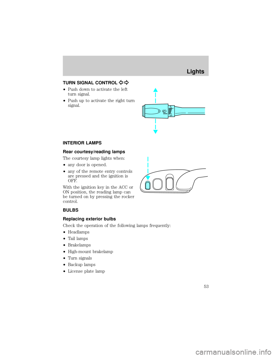
TURN SIGNAL CONTROL
²Push down to activate the left
turn signal.
²Push up to activate the right turn
signal.
INTERIOR LAMPS
Rear courtesy/reading lamps
The courtesy lamp lights when:
²any door is opened.
²any of the remote entry controls
are pressed and the ignition is
OFF.
With the ignition key in the ACC or
ON position, the reading lamp can
be turned on by pressing the rocker
control.
BULBS
Replacing exterior bulbs
Check the operation of the following lamps frequently:
²Headlamps
²Tail lamps
²Brakelamps
²High-mount brakelamp
²Turn signals
²Backup lamps
²License plate lamp
HI
LO
F
S
OFF
Lights
53
Page 54 of 248
Do not remove lamp bulbs unless they will be replaced immediately. If a
bulb is removed for an extended period of time, contaminants may enter
the lamp housings and affect performance.
Using the right bulbs
Replacement bulbs are specified in the chart below. Headlamp bulbs
must be marked with an authorized ªD.O.T.º for North America and an
ªEº for Europe to assure lamp performance, light brightness and pattern
and safe visibility. The correct bulbs will not damage the lamp assembly
or void the lamp assembly warranty and will provide quality bulb burn
time.
Function Trade Number
Tail lamp, brakelamp, turn lamp 3157K
Backup lamp 3156K
Side marker lamp (front) 194
Park, turn lamp (front) 3157 AK (amber)
Headlamp 9007
Cornering lamp 3156K
License plate lamp 168
High-mount brakelamp 912
Luggage compartment lamp 212-2
Map lamp 578
Visor vanity lamp 168
Door courtesy lamp 904
Glove compartment 194
All replacement bulbs are clear in color except where noted.
To replace all instrument panel lights - see your dealer.
Replacing the interior bulbs
Check the operation of the following interior bulbs frequently:
²interior overhead lamp
²map lamp
For bulb replacement, see a dealer or qualified technician.
Lights
54
Page 58 of 248
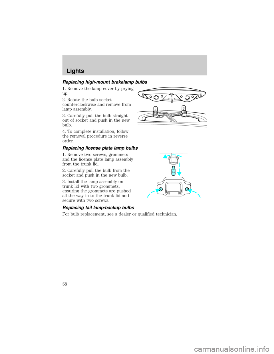
Replacing high-mount brakelamp bulbs
1. Remove the lamp cover by prying
up.
2. Rotate the bulb socket
counterclockwise and remove from
lamp assembly.
3. Carefully pull the bulb straight
out of socket and push in the new
bulb.
4. To complete installation, follow
the removal procedure in reverse
order.
Replacing license plate lamp bulbs
1. Remove two screws, grommets
and the license plate lamp assembly
from the trunk lid.
2. Carefully pull the bulb from the
socket and push in the new bulb.
3. Install the lamp assembly on
trunk lid with two grommets,
ensuring the grommets are pushed
all the way in to the trunk lid and
secure with two screws.
Replacing tail lamp/backup bulbs
For bulb replacement, see a dealer or qualified technician.
Lights
58
Page 64 of 248
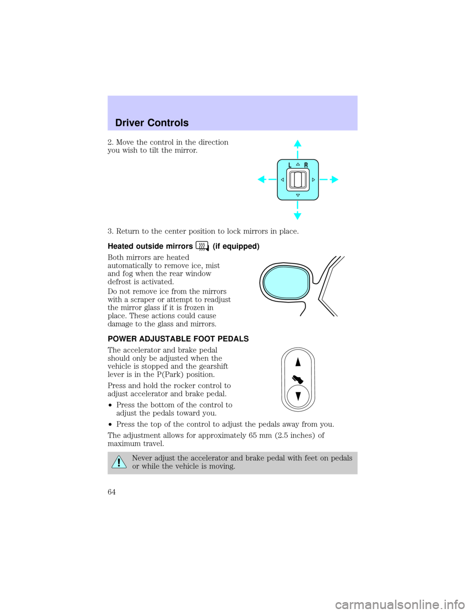
2. Move the control in the direction
you wish to tilt the mirror.
3. Return to the center position to lock mirrors in place.
Heated outside mirrors
(if equipped)
Both mirrors are heated
automatically to remove ice, mist
and fog when the rear window
defrost is activated.
Do not remove ice from the mirrors
with a scraper or attempt to readjust
the mirror glass if it is frozen in
place. These actions could cause
damage to the glass and mirrors.
POWER ADJUSTABLE FOOT PEDALS
The accelerator and brake pedal
should only be adjusted when the
vehicle is stopped and the gearshift
lever is in the P(Park) position.
Press and hold the rocker control to
adjust accelerator and brake pedal.
²Press the bottom of the control to
adjust the pedals toward you.
²Press the top of the control to adjust the pedals away from you.
The adjustment allows for approximately 65 mm (2.5 inches) of
maximum travel.
Never adjust the accelerator and brake pedal with feet on pedals
or while the vehicle is moving.
LR
Driver Controls
64
Page 66 of 248
If you drive up or down a steep hill, your vehicle speed may vary
momentarily slower or faster than the set speed. This is normal.
Speed control cannot reduce the vehicle speed if it increases above the
set speed on a downhill. If your vehicle speed is faster than the set
speed while driving on a downhill, you may want to shift to the next
lower gear or apply the brakes to reduce your vehicle speed.
If your vehicle slows down more than 16 km/h (10 mph) below your set
speed on an uphill, your speed control will disengage. This is normal.
Pressing RES/RESUME will re-engage it.
Do not use the speed control in heavy traffic or on roads that
are winding, slippery, or unpaved.
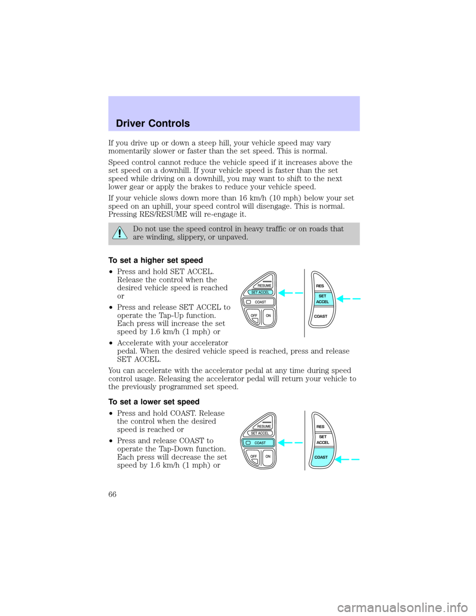
To set a higher set speed
²Press and hold SET ACCEL.
Release the control when the
desired vehicle speed is reached
or
²Press and release SET ACCEL to
operate the Tap-Up function.
Each press will increase the set
speed by 1.6 km/h (1 mph) or
²Accelerate with your accelerator
pedal. When the desired vehicle speed is reached, press and release
SET ACCEL.
You can accelerate with the accelerator pedal at any time during speed
control usage. Releasing the accelerator pedal will return your vehicle to
the previously programmed set speed.
To set a lower set speed
²Press and hold COAST. Release
the control when the desired
speed is reached or
²Press and release COAST to
operate the Tap-Down function.
Each press will decrease the set
speed by 1.6 km/h (1 mph) or
RES
SET
ACCEL
COAST
RES
SET
ACCEL
COAST
Driver Controls
66