location LINCOLN TOWN CAR 2002 Owners Manual
[x] Cancel search | Manufacturer: LINCOLN, Model Year: 2002, Model line: TOWN CAR, Model: LINCOLN TOWN CAR 2002Pages: 248, PDF Size: 1.9 MB
Page 43 of 248
ELECTRONIC AUTOMATIC TEMPERATURE CONTROL (EATC)
SYSTEM
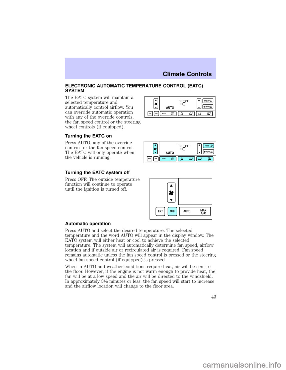
The EATC system will maintain a
selected temperature and
automatically control airflow. You
can override automatic operation
with any of the override controls,
the fan speed control or the steering
wheel controls (if equipped).
Turning the EATC on
Press AUTO, any of the override
controls or the fan speed control.
The EATC will only operate when
the vehicle is running.
Turning the EATC system off
Press OFF. The outside temperature
function will continue to operate
until the ignition is turned off.
Automatic operation
Press AUTO and select the desired temperature. The selected
temperature and the word AUTO will appear in the display window. The
EATC system will either heat or cool to achieve the selected
temperature. The system will automatically determine fan speed, airflow
location and if outside air or recirculated air is required. Fan speed
remains automatic unless the fan speed control is pressed or the steering
wheel fan speed control (if equipped) is pressed.
When in AUTO and weather conditions require heat, air will be sent to
the floor. However, if the engine is not warm enough to provide heat, the
fan will be at a low speed and the air will be directed to the windshield.
In approximately 3
1¤2minutes or less, the fan speed will start to increase
and the airflow location will change to the floor area.
˚F
AUTO
EXT OFF AUTOMAX
A/CFRONT
REAR
˚F
AUTO
EXT OFF AUTOMAX
A/CFRONT
REAR
EXT OFF AUTOMAX
A/C
Climate Controls
43
Page 44 of 248
If unusual conditions exist (i.e.-window fogging, etc.), the manual
override controls allow you to select airflow locations and the fan control
allows you to adjust fan speed as necessary.
Temperature selection
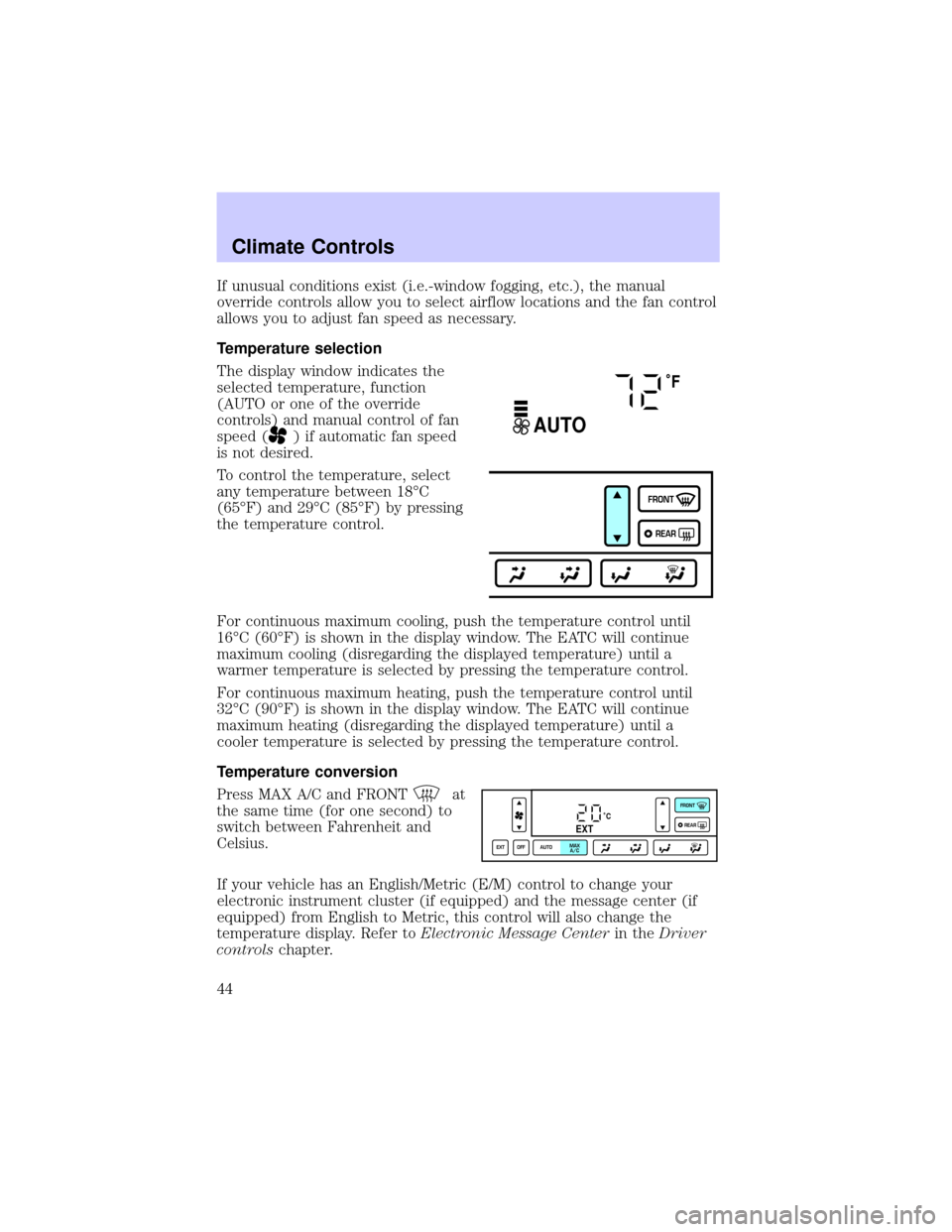
The display window indicates the
selected temperature, function
(AUTO or one of the override
controls) and manual control of fan
speed (
) if automatic fan speed
is not desired.
To control the temperature, select
any temperature between 18ÉC
(65ÉF) and 29ÉC (85ÉF) by pressing
the temperature control.
For continuous maximum cooling, push the temperature control until
16ÉC (60ÉF) is shown in the display window. The EATC will continue
maximum cooling (disregarding the displayed temperature) until a
warmer temperature is selected by pressing the temperature control.
For continuous maximum heating, push the temperature control until
32ÉC (90ÉF) is shown in the display window. The EATC will continue
maximum heating (disregarding the displayed temperature) until a
cooler temperature is selected by pressing the temperature control.
Temperature conversion
Press MAX A/C and FRONT
at
the same time (for one second) to
switch between Fahrenheit and
Celsius.
If your vehicle has an English/Metric (E/M) control to change your
electronic instrument cluster (if equipped) and the message center (if
equipped) from English to Metric, this control will also change the
temperature display. Refer toElectronic Message Centerin theDriver
controlschapter.
˚F
AUTO
FRONT
REAR
˚CEXT
EXT OFF AUTOMAX
A/CFRONT
REAR
Climate Controls
44
Page 47 of 248

If a manual override function is selected while the outside temperature is
displayed, the new function will be displayed for four seconds after it is
changed, then the outside temperature will return to the window along
with the override selection.
The outside temperature reading is most accurate when the vehicle is
moving. Higher readings may be obtained when the vehicle is not
moving. The readings that you get may not agree with temperatures
given on the radio due to differences in vehicle and station locations.
Operating tips
²In humid weather, select
(Defrost) before driving. This will
reduce fogging on your windshield. Once the windshield has been
cleared, operate the climate control system as desired.
²To reduce humidity buildup inside the vehicle in cold weather
conditions, do not drive with the climate control system in the OFF or
MAX A/C position.
²To reduce humidity buildup inside the vehicle in warm weather
conditions, do not drive with the climate control system in the OFF
position.
²Under normal weather conditions, your vehicle's climate control
system should be left in any position other than MAX A/C or OFF
when the vehicle is parked. This allows the vehicle to ªbreatheº
through the outside air inlet duct.
²Under snowy or dirty weather conditions, your vehicle's climate
control system should be left in the OFF position when the vehicle is
parked. This allows the climate control system to be free from
contamination of outside pollutants.
²If your vehicle has been parked with the windows closed during warm
weather conditions, the air conditioner will perform more efficiently in
cooling the vehicle if driven for two or three minutes with the
windows open. This will force most of the hot, stale air out of the
vehicle. Once the vehicle has been ªaired outº, operate the climate
control system as desired.
²Do not place objects under the front seat that will interfere with the
airflow to the rear seats.
²Remove any snow, ice or leaves from the air intake area at the base of
the windshield.
Climate Controls
47
Page 74 of 248
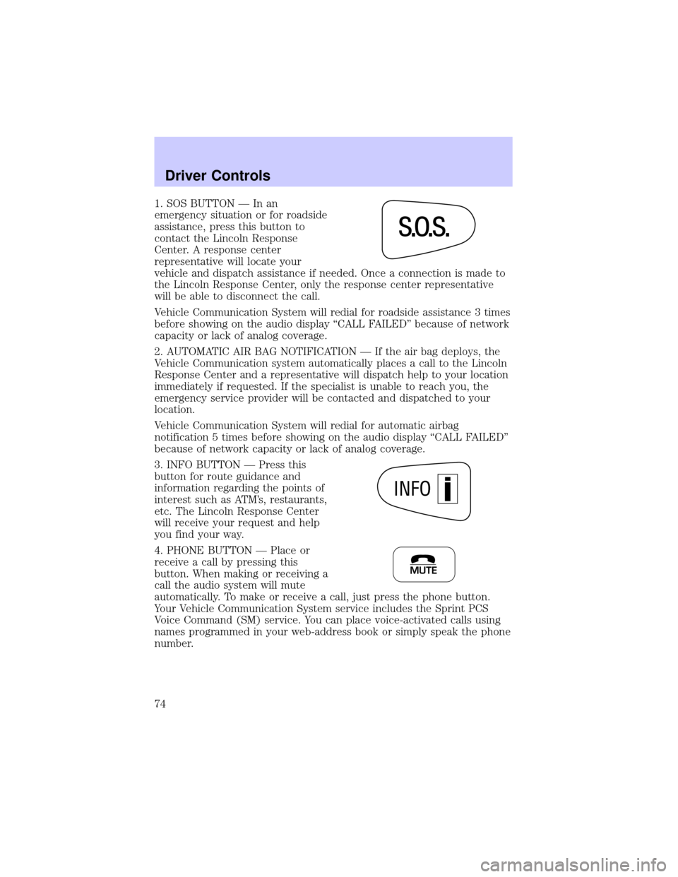
1. SOS BUTTON Ð In an
emergency situation or for roadside
assistance, press this button to
contact the Lincoln Response
Center. A response center
representative will locate your
vehicle and dispatch assistance if needed. Once a connection is made to
the Lincoln Response Center, only the response center representative
will be able to disconnect the call.
Vehicle Communication System will redial for roadside assistance 3 times
before showing on the audio display ªCALL FAILEDº because of network
capacity or lack of analog coverage.
2. AUTOMATIC AIR BAG NOTIFICATION Ð If the air bag deploys, the
Vehicle Communication system automatically places a call to the Lincoln
Response Center and a representative will dispatch help to your location
immediately if requested. If the specialist is unable to reach you, the
emergency service provider will be contacted and dispatched to your
location.
Vehicle Communication System will redial for automatic airbag
notification 5 times before showing on the audio display ªCALL FAILEDº
because of network capacity or lack of analog coverage.
3. INFO BUTTON Ð Press this
button for route guidance and
information regarding the points of
interest such as ATM's, restaurants,
etc. The Lincoln Response Center
will receive your request and help
you find your way.
4. PHONE BUTTON Ð Place or
receive a call by pressing this
button. When making or receiving a
call the audio system will mute
automatically. To make or receive a call, just press the phone button.
Your Vehicle Communication System service includes the Sprint PCS
Voice Command (SM) service. You can place voice-activated calls using
names programmed in your web-address book or simply speak the phone
number.
ss
. . .o
INFO
MUTE
Driver Controls
74
Page 76 of 248

Vehicle Communication System Limitations
²Vehicle Communication System services are available in the 48
contiguous states and Hawaii
²Vehicle Communication System services are not available in Alaska
²Only available within range of the cellular systems
²Connection limited by atmospheric and topographical conditions
²Connection limited by cellular network capabilities and infrastructure
²The wireless phone must have an active wireless service plan with
Sprint PCS and docked in the docking station located in the center
console for Vehicle Communication System to function properly
²The vehicle must be running or the ignition must be turned to either
ªACCº or ªRUN/ONº position
²May become inoperative if the vehicle is involved in an accident,
damaging one or more components
²Sprint PCS Voice Command (SM) services are only available on the
Sprint PCS network
Global Positioning Satellites are used to deliver location information
(only at the request of the vehicle occupants or in the event an airbag
deploys) and may not be available if signal is obstructed. (If a signal is
unavailable, the last valid position obtained before the signal was
obstructed will be sent.)
Vehicle Communication System is powered by the vehicle's battery and
will not operate if the battery is discharged or disconnected.
Vehicle Communication System specialist will make all reasonable efforts
to contact the Public Safety service providers but cannot be held
responsible for their response time or their activities.
Drivers have the responsibility to pay primary attention to the road and
drive safely. A driver may want to pull over to a safe parking spot before
using Vehicle Communication System services. Drivers who allow
themselves to become distracted may cause an accident. Please use this
technology responsibly.
Due to the specialized Lincoln software contained within the phone, your
local Sprint PCS store is unable to provide service or replacement units.
Issues or questions about equipment including the wireless phone should
be directed to your Lincoln dealer.
Driver Controls
76
Page 79 of 248
Compass zone adjustment
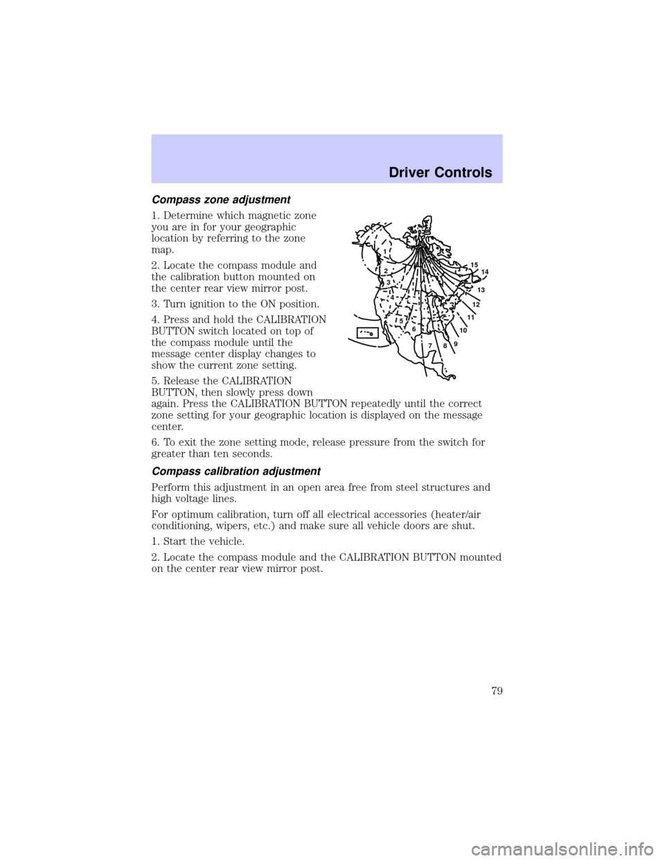
1. Determine which magnetic zone
you are in for your geographic
location by referring to the zone
map.
2. Locate the compass module and
the calibration button mounted on
the center rear view mirror post.
3. Turn ignition to the ON position.
4. Press and hold the CALIBRATION
BUTTON switch located on top of
the compass module until the
message center display changes to
show the current zone setting.
5. Release the CALIBRATION
BUTTON, then slowly press down
again. Press the CALIBRATION BUTTON repeatedly until the correct
zone setting for your geographic location is displayed on the message
center.
6. To exit the zone setting mode, release pressure from the switch for
greater than ten seconds.
Compass calibration adjustment
Perform this adjustment in an open area free from steel structures and
high voltage lines.
For optimum calibration, turn off all electrical accessories (heater/air
conditioning, wipers, etc.) and make sure all vehicle doors are shut.
1. Start the vehicle.
2. Locate the compass module and the CALIBRATION BUTTON mounted
on the center rear view mirror post.
1
2
3
4
5
6
7891011121314 15
Driver Controls
79
Page 89 of 248
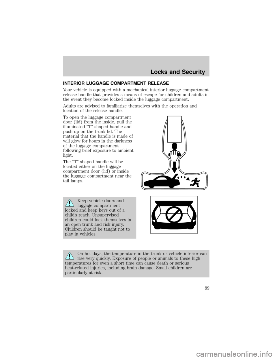
INTERIOR LUGGAGE COMPARTMENT RELEASE
Your vehicle is equipped with a mechanical interior luggage compartment
release handle that provides a means of escape for children and adults in
the event they become locked inside the luggage compartment.
Adults are advised to familiarize themselves with the operation and
location of the release handle.
To open the luggage compartment
door (lid) from the inside, pull the
illuminated ªTº shaped handle and
push up on the trunk lid. The
material that the handle is made of
will glow for hours in the darkness
of the luggage compartment
following brief exposure to ambient
light.
The ªTº shaped handle will be
located either on the luggage
compartment door (lid) or inside
the luggage compartment near the
tail lamps.
Keep vehicle doors and
luggage compartment
locked and keep keys out of a
child's reach. Unsupervised
children could lock themselves in
an open trunk and risk injury.
Children should be taught not to
play in vehicles.
On hot days, the temperature in the trunk or vehicle interior can
rise very quickly. Exposure of people or animals to these high
temperatures for even a short time can cause death or serious
heat-related injuries, including brain damage. Small children are
particularly at risk.
Locks and Security
89
Page 160 of 248
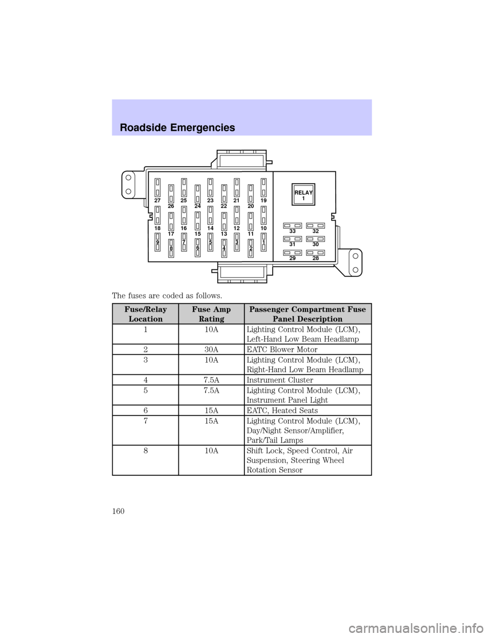
The fuses are coded as follows.
Fuse/Relay
LocationFuse Amp
RatingPassenger Compartment Fuse
Panel Description
1 10A Lighting Control Module (LCM),
Left-Hand Low Beam Headlamp
2 30A EATC Blower Motor
3 10A Lighting Control Module (LCM),
Right-Hand Low Beam Headlamp
4 7.5A Instrument Cluster
5 7.5A Lighting Control Module (LCM),
Instrument Panel Light
6 15A EATC, Heated Seats
7 15A Lighting Control Module (LCM),
Day/Night Sensor/Amplifier,
Park/Tail Lamps
8 10A Shift Lock, Speed Control, Air
Suspension, Steering Wheel
Rotation Sensor
27 25
26 2423 21
2219
20
18 16
17 1514 12
1310
33
31
2932
30
28 11
97
8653
41
2RELAY
1
Roadside Emergencies
160
Page 161 of 248
Fuse/Relay
LocationFuse Amp
RatingPassenger Compartment Fuse
Panel Description
9 20A Lighting Control Module (LCM),
Multi-Function Switch, Hi Beam
Headlamps
10 10A Restraint Control Module (RCM),
Air Bags
11 Ð Not Used
12 15A Instrument Cluster, Anti-Theft,
Ignition Switch, Ignition Coils
13 10A Anti-Lock Brake Module, Traction
Control Switch
14 7.5A Transmission Control Switch,
Lighting Control Module (LCM),
VCS
15 20A Multi-Function Switch, Turn
Signals
16 30A Wiper Control Module (WCM),
Windshield Wiper Motor
17 10A Digital Transmission Range (DTR)
Sensor, Back-Up Lamps, EC
Mirrors
18 7.5A Lighting Control Module (LCM),
Front Radio Control Unit, Cellular
Telephone Transceiver, Electronic
Day/Night Mirror, Compass
Module/Rear Audio/Climate
Control Module, VCS
19 10A EATC, Clock, Instrument Cluster,
PCM
20 7.5A Lighting Control Module (LCM),
ABS, Shift Lock
21 20A Multi-Function Switch, Hazard
Lamps
Roadside Emergencies
161
Page 162 of 248
Fuse/Relay
LocationFuse Amp
RatingPassenger Compartment Fuse
Panel Description
22 20A Multi-Function Switch, High
Mounted Stop Lamps, Stop Lamps
23 20A Datalink Connector, I/P Cigar
Lighter, Reardoor Cigar Lighters
(Long Wheel Base Only)
24 5A Front Radio Control Unit
25 15A Lighting Control Module (LCM),
Courtesy/Demand Lamps
26 5A Digital Transmission Range (DTR)
Sensor, Starter Relay Coil
27 20A Fuel Filler Door Release Switch
28 10A Heated Mirrors
29 20A LF Door Module, Door Locks,
Decklid Release
30 7.5A LF Seat Module, Trunk Lid
Release Switch, Door Lock
Switches, LF Seat Control Switch,
LF Door Module, Power Mirror
Switch
31 7.5A Main Light Switch, Lighting
Control Module (LCM)
32 25A Brake Pedal Position Switch
(BPP), Brake Pressure Switch,
Fuses 20 and 22
33 15A Front Radio Control Unit, Digital
Compact Disk Changer, Cellular
Telephone Transceiver, VCS
Relay 1 Ð Accessory Delay Relay
(Signature/Cartier) or Power
Window Relay (Executive)
Roadside Emergencies
162