warning lights LINCOLN TOWN CAR 2002 Owners Manual
[x] Cancel search | Manufacturer: LINCOLN, Model Year: 2002, Model line: TOWN CAR, Model: LINCOLN TOWN CAR 2002Pages: 248, PDF Size: 1.9 MB
Page 1 of 248
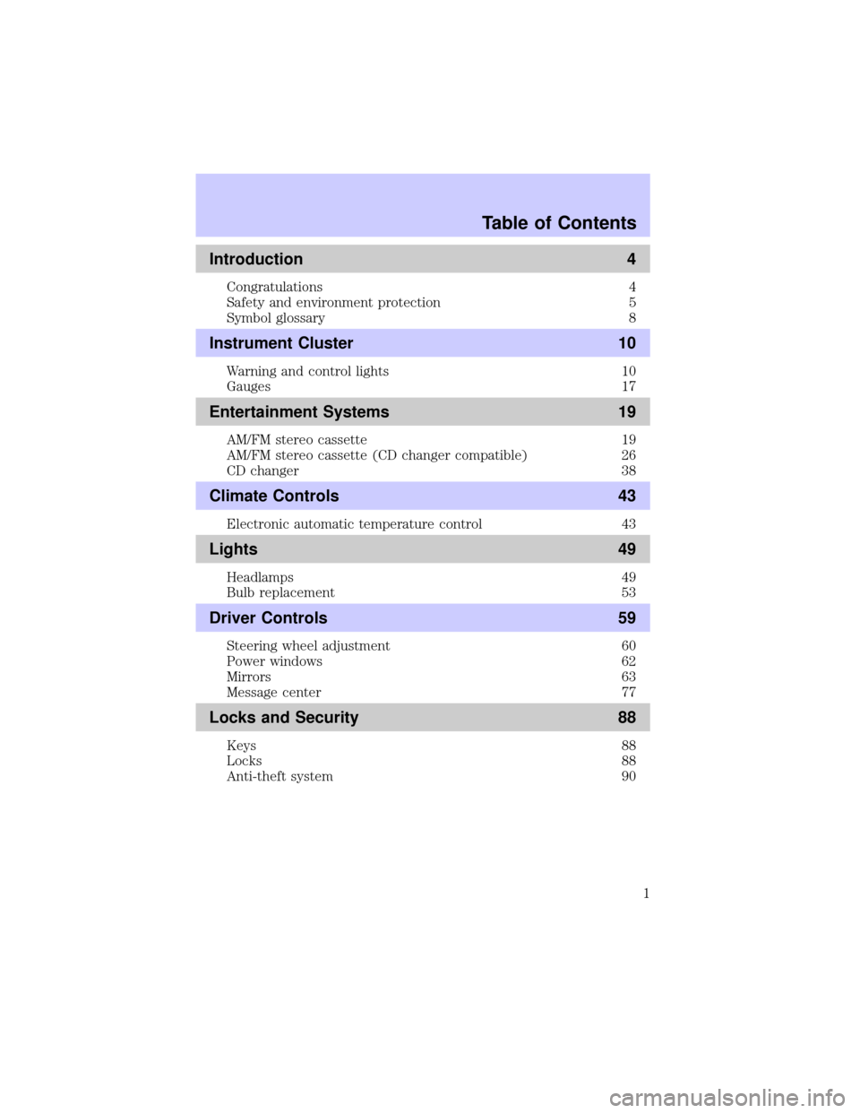
Introduction 4
Congratulations 4
Safety and environment protection 5
Symbol glossary 8
Instrument Cluster 10
Warning and control lights 10
Gauges 17
Entertainment Systems 19
AM/FM stereo cassette 19
AM/FM stereo cassette (CD changer compatible) 26
CD changer 38
Climate Controls 43
Electronic automatic temperature control 43
Lights 49
Headlamps 49
Bulb replacement 53
Driver Controls 59
Steering wheel adjustment 60
Power windows 62
Mirrors 63
Message center 77
Locks and Security 88
Keys 88
Locks 88
Anti-theft system 90
Table of Contents
1
Page 10 of 248
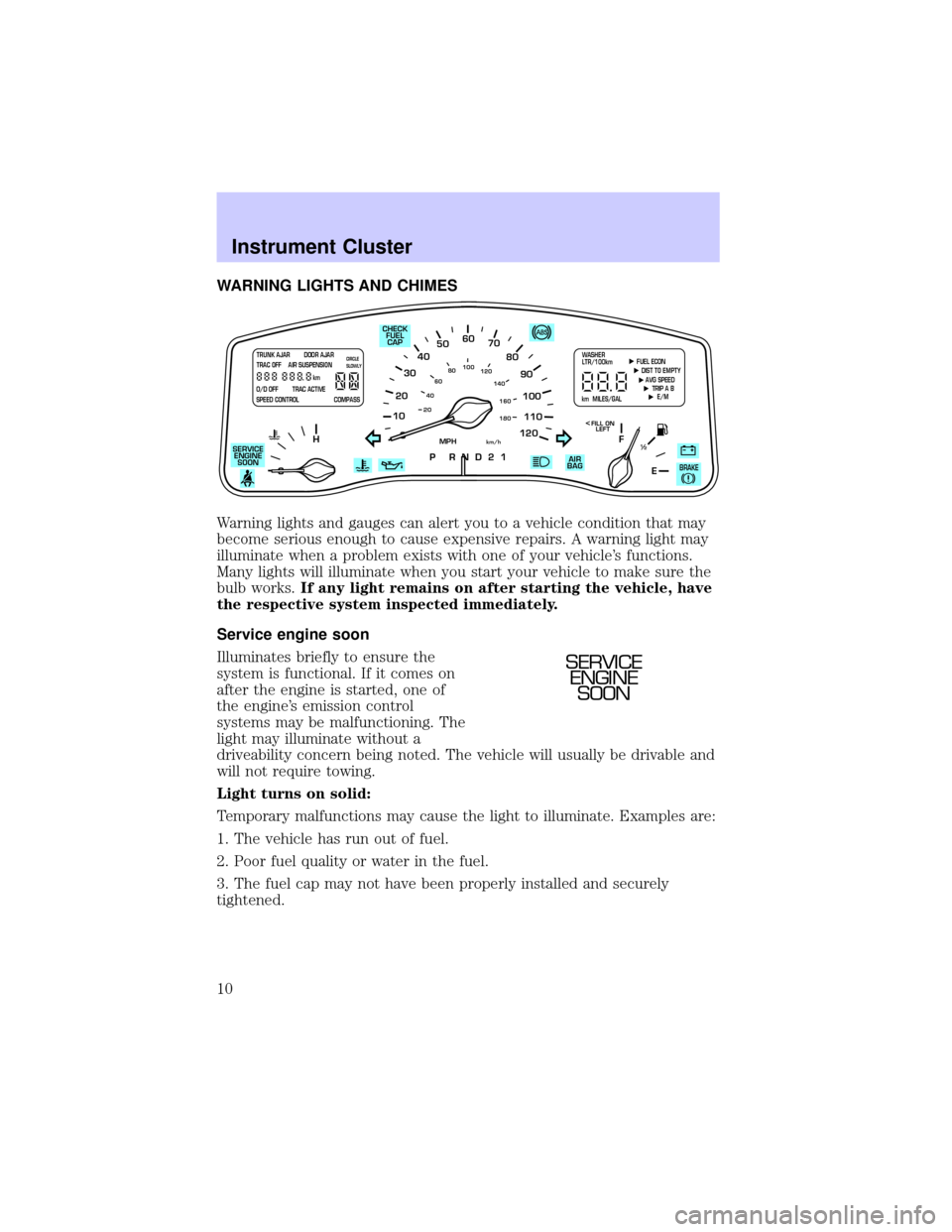
WARNING LIGHTS AND CHIMES
Warning lights and gauges can alert you to a vehicle condition that may
become serious enough to cause expensive repairs. A warning light may
illuminate when a problem exists with one of your vehicle's functions.
Many lights will illuminate when you start your vehicle to make sure the
bulb works.If any light remains on after starting the vehicle, have
the respective system inspected immediately.
Service engine soon
Illuminates briefly to ensure the
system is functional. If it comes on
after the engine is started, one of
the engine's emission control
systems may be malfunctioning. The
light may illuminate without a
driveability concern being noted. The vehicle will usually be drivable and
will not require towing.
Light turns on solid:
Temporary malfunctions may cause the light to illuminate. Examples are:
1. The vehicle has run out of fuel.
2. Poor fuel quality or water in the fuel.
3. The fuel cap may not have been properly installed and securely
tightened.
10
2030405060
70
80
90
100
120206080
40100
120
160 140
180
P R N D 2 1
MPHkm/h
110
HF
E1
2
FILL ON
LEFT<
AIR
BAG CHECK
FUEL
CAP
SERVICE
ENGINE
SOON
TRUNK AJAR DOOR AJAR
TRAC OFF AIR SUSPENSION
O/D OFF TRAC ACTIVE
SPEED CONTROL COMPASSkmCIRCLE
SLOWLY FUEL ECON
DIST TO EMPTY
AVG SPEED
TRIP A B
E/M
km MILES/GALWASHER
LTR/100km
BRAKE
SERVICE
ENGINE
SOON
Instrument Cluster
10
Page 107 of 248

²Front crash severity sensor.
²Restraints Control Module (RCM) with impact and safing sensors.
²Restraint system warning light and back-up tone.
²The electrical wiring for the air bags, crash sensor(s), safety belt
pretensioners, front safety belt usage sensors, driver seat position
sensor, passenger occupant classification sensor (if equipped), and
indicator lights.
How does the personal safety system work?
The Personal safety system can adapt the deployment strategy of your
vehicle's safety devices according to crash severity and occupant
conditions. A collection of crash and occupant sensors provides
information to the Restraints control module (RCM). During a crash, the
RCM activates the safety belt pretensioners and/or either one or both
stages of the dual-stage air bag supplemental restraints based on crash
severity and occupant conditions.
The fact that the pretensioners or air bags did not activate for both front
seat occupants in a collision does not mean that something is wrong with
the system. Rather, it means the Personal safety system determined the
accident conditions (crash severity, belt usage, etc.) were not
appropriate to activate these safety devices. Front air bags and
pretensioners are designed to activate only in frontal and near-frontal
collisions, not rollovers, side-impacts, or rear-impacts unless the collision
causes sufficient longitudinal deceleration.
Driver and passenger dual-stage air bag supplemental restraints
The dual-stage air bags offer the capability to tailor the level of air bag
inflation energy. A lower, less forceful energy level is provided for more
common, moderate-severity impacts. A higher energy level is used for
the most severe impacts. Refer toAir bag supplemental restraints
section in this chapter.
Front crash severity sensor
The front crash severity sensor enhances the ability to detect the
severity of an impact. Positioned up front, it provides valuable
information early in the crash event on the severity of the impact. This
allows your Personal safety system to distinguish between different levels
of crash severity and modify the deployment strategy of the dual-stage
air bags and safety belt pretensioners.
Seating and Safety Restraints
107
Page 109 of 248

Front safety belt usage sensors
The front safety belt usage sensors detect whether or not the driver and
front outboard passenger safety belts are fastened. This information
allows your Personal safety system to tailor the air bag deployment and
safety belt pretensioner activation depending upon safety belt usage.
Refer toSafety beltsection in this chapter.
Front safety belt pretensioners
The safety belt pretensioners are designed to tighten the safety belts
firmly against the occupant's body during a collision. This maximizes the
effectiveness of the safety belts and helps properly position the occupant
relative to the air bag to improve protection. The safety belt
pretensioners can be either activated alone or, if the collision is of
sufficient severity, together with the air bags.
Front safety belt energy management retractors
The front safety belt energy management retractors allow webbing to be
pulled out of the retractor in a gradual and controlled manner in
response to the occupant's forward momentum. This helps reduce the
risk of force-related injuries to the occupant's chest by limiting the load
on the occupant. Refer toSafety beltsection in this chapter.
Determining if the Personal safety system is operational
The Personal safety system uses a warning light in the instrument cluster
or a back-up tone to indicate the condition of the system. Refer to the
Warning lightsection in theInstrument clusterchapter. Routine
maintenance of the Personal safety system is not required.
The Restraints control module (RCM) monitors its own internal circuits
and the circuits for the air bag supplemental restraints, crash sensor(s),
safety belt pretensioners, front safety belt buckle sensors, driver seat
position sensor, and passenger occupant classification sensor (if
equipped). In addition, the RCM also monitors the restraints warning
light in the instrument cluster. A difficulty with the system is indicated
by one or more of the following.
²The warning light will either flash or stay lit.
²The warning light will not illuminate immediately after ignition is
turned on.
²A series of five beeps will be heard. The tone pattern will repeat
periodically until the problem and warning light are repaired.
Seating and Safety Restraints
109
Page 136 of 248
STARTING
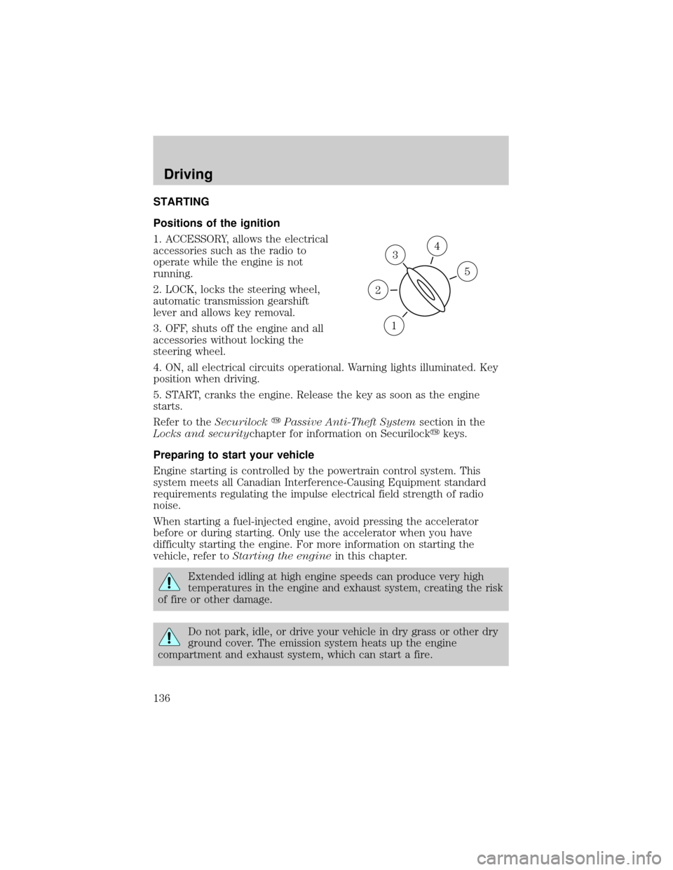
Positions of the ignition
1. ACCESSORY, allows the electrical
accessories such as the radio to
operate while the engine is not
running.
2. LOCK, locks the steering wheel,
automatic transmission gearshift
lever and allows key removal.
3. OFF, shuts off the engine and all
accessories without locking the
steering wheel.
4. ON, all electrical circuits operational. Warning lights illuminated. Key
position when driving.
5. START, cranks the engine. Release the key as soon as the engine
starts.
Refer to theSecurilockyPassive Anti-Theft Systemsection in the
Locks and securitychapter for information on Securilockykeys.
Preparing to start your vehicle
Engine starting is controlled by the powertrain control system. This
system meets all Canadian Interference-Causing Equipment standard
requirements regulating the impulse electrical field strength of radio
noise.
When starting a fuel-injected engine, avoid pressing the accelerator
before or during starting. Only use the accelerator when you have
difficulty starting the engine. For more information on starting the
vehicle, refer toStarting the enginein this chapter.
Extended idling at high engine speeds can produce very high
temperatures in the engine and exhaust system, creating the risk
of fire or other damage.
Do not park, idle, or drive your vehicle in dry grass or other dry
ground cover. The emission system heats up the engine
compartment and exhaust system, which can start a fire.
3
1
2
5
4
Driving
136
Page 143 of 248
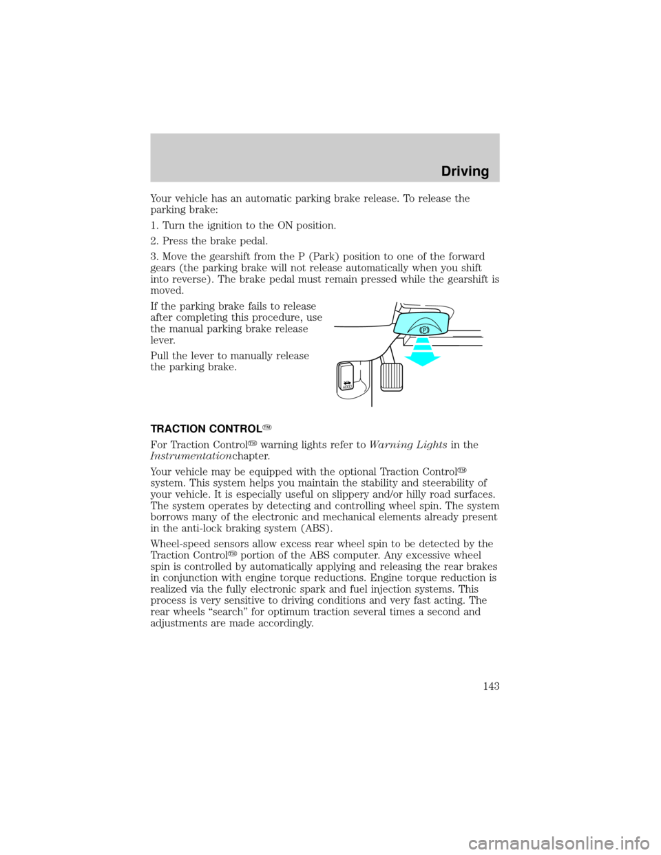
Your vehicle has an automatic parking brake release. To release the
parking brake:
1. Turn the ignition to the ON position.
2. Press the brake pedal.
3. Move the gearshift from the P (Park) position to one of the forward
gears (the parking brake will not release automatically when you shift
into reverse). The brake pedal must remain pressed while the gearshift is
moved.
If the parking brake fails to release
after completing this procedure, use
the manual parking brake release
lever.
Pull the lever to manually release
the parking brake.
TRACTION CONTROLY
For Traction Controlywarning lights refer toWarning Lightsin the
Instrumentationchapter.
Your vehicle may be equipped with the optional Traction Controly
system. This system helps you maintain the stability and steerability of
your vehicle. It is especially useful on slippery and/or hilly road surfaces.
The system operates by detecting and controlling wheel spin. The system
borrows many of the electronic and mechanical elements already present
in the anti-lock braking system (ABS).
Wheel-speed sensors allow excess rear wheel spin to be detected by the
Traction Controlyportion of the ABS computer. Any excessive wheel
spin is controlled by automatically applying and releasing the rear brakes
in conjunction with engine torque reductions. Engine torque reduction is
realized via the fully electronic spark and fuel injection systems. This
process is very sensitive to driving conditions and very fast acting. The
rear wheels ªsearchº for optimum traction several times a second and
adjustments are made accordingly.
HOOD
Driving
143
Page 217 of 248
Please consult yourWarranty Guidefor complete emission warranty
information.
Readiness for Inspection/Maintenance (I/M) testing
In some localities, it may be a legal requirement to pass an I/M test of
the on-board diagnostics system. If your ªCheck Engine/Service Engine
Soonº light is on, refer to the description in theWarning lights and
chimessection of theInstrument Clusterchapter. Your vehicle may not
pass the I/M test with the ªCheck Engine/Service Engine Soonº light on.
If the vehicle's powertrain system or its battery has just been serviced,
the on-board diagnostics system is reset to a ªnot ready for I/M testº
condition. To ready the on-board diagnostics system for I/M testing, a
minimum of 30 minutes of city and highway driving is necessary as
described below:
²First, at least 10 minutes of driving on an expressway or highway.
²Next, at least 20 minutes driving in stop-and-go, city-type traffic with
at least four idle periods.
Allow the vehicle to sit for at least eight hours without starting the
engine. Then, start the engine and complete the above driving cycle. The
engine must warm up to its normal operating temperature. Once started,
do not turn off the engine until the above driving cycle is complete.
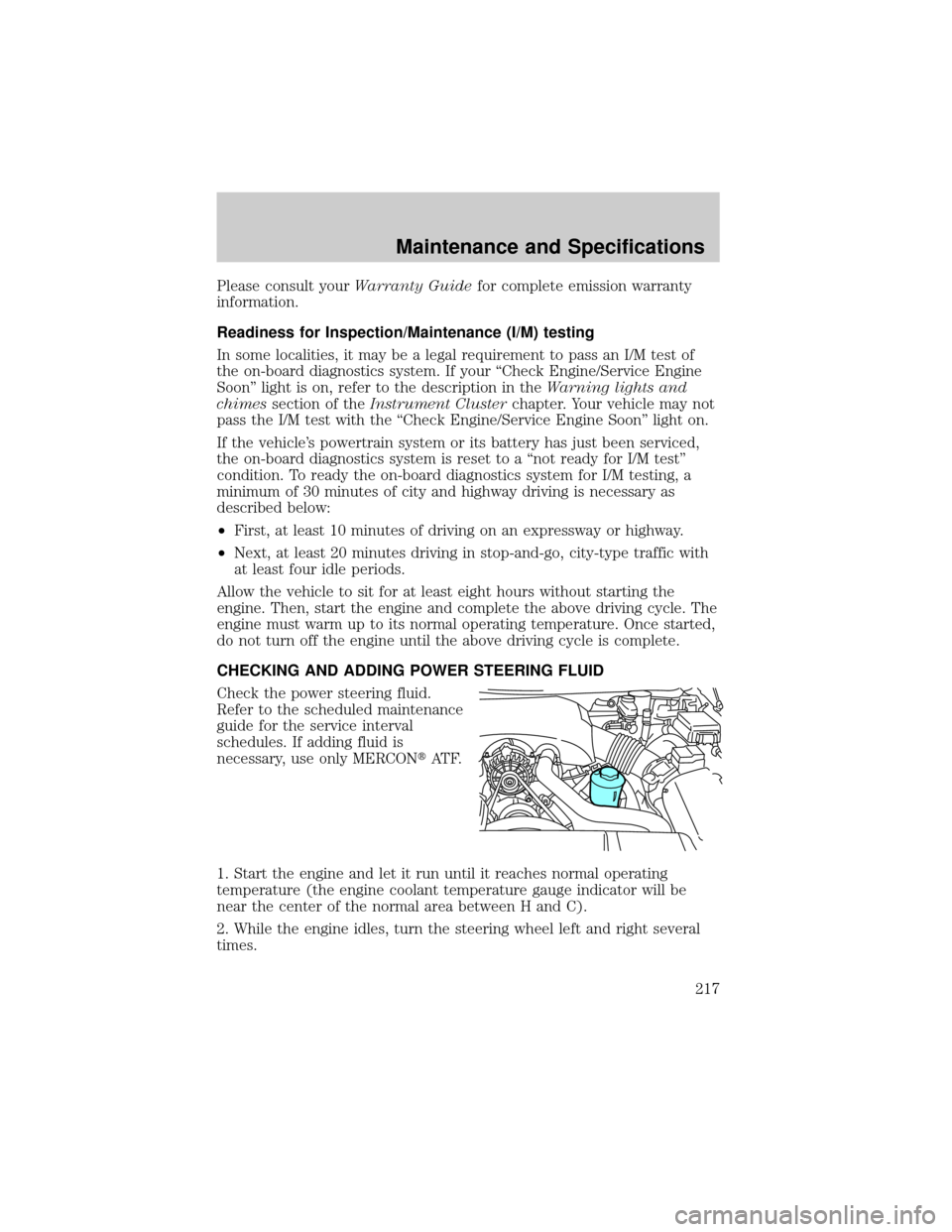
CHECKING AND ADDING POWER STEERING FLUID
Check the power steering fluid.
Refer to the scheduled maintenance
guide for the service interval
schedules. If adding fluid is
necessary, use only MERCONtAT F.
1. Start the engine and let it run until it reaches normal operating
temperature (the engine coolant temperature gauge indicator will be
near the center of the normal area between H and C).
2. While the engine idles, turn the steering wheel left and right several
times.
Maintenance and Specifications
217
Page 240 of 248

bulb specifications ....................54
daytime running lights .............49
flash to pass ..............................50
high beam ...........................15, 50
replacing bulbs .........................55
turning on and off ....................49
warning chime ..........................16
HomeLink universal
transceiver (see Garage door
opener) ..................................69±72
Hood ..........................................194
I
Ignition ...............................136, 230
Infant seats
(see Safety seats) .............129±130
Inspection/maintenance (I/M)
testing ........................................217
Instrument panel
cleaning ...................................190
cluster ................................10, 190
lighting up panel and
interior .......................................50
J
Jack ............................................165
positioning ...............................165
storage .....................................165
Jump-starting your vehicle ......169
K
Keyless entry system .................96
autolock .....................................94
keypad .......................................96
programming entry code .........96Keys ...............................88, 98±100
key in ignition chime ...............16
positions of the ignition .........136
L
Lamps
autolamp system .......................49
bulb replacement
specifications chart ..................54
cargo lamps ...............................50
daytime running light ...............49
headlamps .................................49
headlamps, flash to pass ..........50
instrument panel, dimming .....50
interior lamps .....................53±54
replacing bulbs .......53, 55, 57±58
Lane change indicator (see
Turn signal) .................................53
Lights, warning and indicator ....10
air bag ........................................12
air suspension ...........................14
anti-lock brakes (ABS) ....12, 142
brake ..........................................12
charging system ........................12
cruise indicator .........................14
door ajar ....................................15
fuel cap light .............................11
high beam .................................15
liftgate ajar ................................16
low coolant ................................13
low washer fluid .......................14
oil pressure ...............................13
safety belt .................................12
service engine soon ..................10
speed control ............................68
traction control system ............15
turn signal indicator .................15
Index
240
Page 243 of 248

W
Warning chimes ...........................16
Warning lights (see Lights) .......10
Washer fluid ..............................195
Water, Driving through .............149
Windows
power .........................................62Windshield washer fluid and
wipers
checking and adding fluid .....195
checking and cleaning ..............59
operation ...................................59
replacing wiper blades .............60
Wrecker towing .........................175
Index
243