low side LINCOLN TOWN CAR 2011 Owners Manual
[x] Cancel search | Manufacturer: LINCOLN, Model Year: 2011, Model line: TOWN CAR, Model: LINCOLN TOWN CAR 2011Pages: 306, PDF Size: 2.04 MB
Page 4 of 306
CONGRATULATIONS
Congratulations on acquiring your new Lincoln. Please take the time to
get well acquainted with your vehicle by reading this handbook. The
more you know and understand about your vehicle, the greater the
safety and pleasure you will derive from driving it.
For more information on Ford Motor Company and its products visit the
following website:
•In the United States: www.ford.com
•In Canada: www.ford.ca
•In Mexico: www.ford.com.mx
•In Australia: www.ford.com.au
Additional owner information is given in separate publications.
This Owner’s Guide describes every option and model variant available
and therefore some of the items covered may not apply to your
particular vehicle. Furthermore, due to printing cycles it may describe
options before they are generally available.
Remember to pass on the Owner’s Guide when reselling the vehicle. It is
an integral part of the vehicle.
WARNING: Fuel pump shut-off:In the event of an accident
this feature will automatically cut off the fuel supply to the
engine. It can also be activated through sudden vibration (e.g. collision
when parking). To restart your vehicle, refer toFuel pump shut-offin
theRoadside Emergencieschapter.
SAFETY AND ENVIRONMENT PROTECTION
Warning symbols in this guide
How can you reduce the risk of personal injury to yourself or others? In
this guide, answers to such questions are contained in comments
highlighted by the warning triangle symbol. These comments should be
read and observed.
Introduction
4
2011 Town Car(tow)
Owners Guide, 2nd Printing
USA(fus)
Page 10 of 306
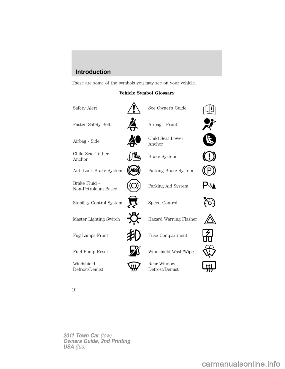
These are some of the symbols you may see on your vehicle.
Vehicle Symbol Glossary
Safety Alert
See Owner’s Guide
Fasten Safety BeltAirbag - Front
Airbag - SideChild Seat Lower
Anchor
Child Seat Tether
AnchorBrake System
Anti-Lock Brake SystemParking Brake System
Brake Fluid -
Non-Petroleum BasedParking Aid System
Stability Control SystemSpeed Control
Master Lighting SwitchHazard Warning Flasher
Fog Lamps-FrontFuse Compartment
Fuel Pump ResetWindshield Wash/Wipe
Windshield
Defrost/DemistRear Window
Defrost/Demist
Introduction
10
2011 Town Car(tow)
Owners Guide, 2nd Printing
USA(fus)
Page 18 of 306
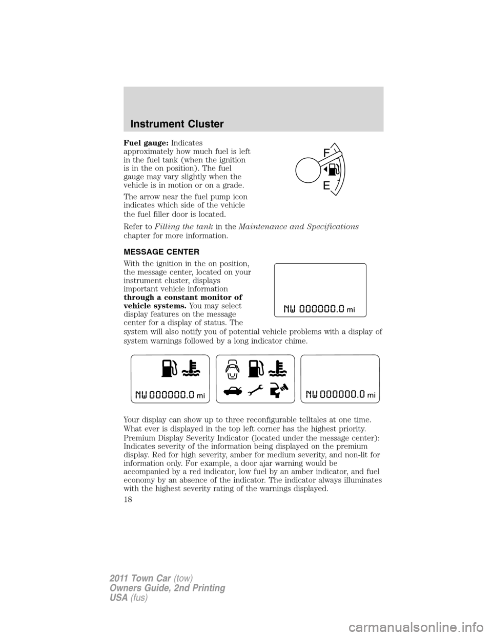
Fuel gauge:Indicates
approximately how much fuel is left
in the fuel tank (when the ignition
is in the on position). The fuel
gauge may vary slightly when the
vehicle is in motion or on a grade.
The arrow near the fuel pump icon
indicates which side of the vehicle
the fuel filler door is located.
Refer toFilling the tankin theMaintenance and Specifications
chapter for more information.
MESSAGE CENTER
With the ignition in the on position,
the message center, located on your
instrument cluster, displays
important vehicle information
through a constant monitor of
vehicle systems.You may select
display features on the message
center for a display of status. The
system will also notify you of potential vehicle problems with a display of
system warnings followed by a long indicator chime.
Your display can show up to three reconfigurable telltales at one time.
What ever is displayed in the top left corner has the highest priority.
Premium Display Severity Indicator (located under the message center):
Indicates severity of the information being displayed on the premium
display. Red for high severity, amber for medium severity, and non-lit for
information only. For example, a door ajar warning would be
accompanied by a red indicator, low fuel by an amber indicator, and fuel
economy by an absence of the indicator. The indicator always illuminates
with the highest severity rating of the warnings displayed.
Instrument Cluster
18
2011 Town Car(tow)
Owners Guide, 2nd Printing
USA(fus)
Page 24 of 306
WARNING:Never remove the coolant reservoir cap while the
engine is running or hot.
CHECK FUEL CAP— Displayed when the fuel filler cap is not
properly installed. Check the fuel filler cap for proper installation. Refer
toFuel filler capin theMaintenance and Specificationschapter.
CHECK AIR SUSPENSION— Displayed when the air suspension
system is not operating properly. If this message is displayed while
driving, pull off the road as soon as safely possible. For more
information, refer toAir suspension systemin theDrivingchapter.
AIR SUSP OFF— Displayed when the air suspension system is turned
off. For more information, refer toAir suspension systemin the
Drivingchapter.
FUEL LEVEL LOW— Displayed as an early reminder of a low fuel
condition. Warning message can be reset by pressing the RESET button,
but will return after 10 minutes. If any other button is pressed besides
RESET, the message ’’PRESS RESET TO CLEAR’’ will appear in the
message center. Once this message disappears (after approximately two
seconds), press RESET to clear the warning.
TRUNK AJAR— Displayed when the trunk is not completely closed.
OVERDRIVE OFF— Displayed when the overdrive is disabled.
OVERDRIVE ON— Displayed when the overdrive is enabled.
LOW TIRE PRESSURE— Displayed when one or more tires on your
vehicle have low tire pressure. Refer toInflating your tiresin theTires,
Wheels and Loadingchapter.
TIRE PRESSURE MONITOR FAULT— Displayed when the Tire
Pressure Monitoring System is malfunctioning. If the warning stays on or
continues to come on, contact your authorized dealer as soon as
possible.
TIRE PRESSURE SENSOR FAULT— Displayed when a tire pressure
sensor is malfunctioning, or your spare tire is in use (Note: this includes
the use of the optional full-sized matching spare tire and wheel). For
more information on how the system operates under these conditions,
refer toTire Pressure Monitoring System (TPMS)in theTires, Wheels
and Loadingchapter. If the warning stays on or continues to come on,
contact your authorized dealer as soon as possible.
Instrument Cluster
24
2011 Town Car(tow)
Owners Guide, 2nd Printing
USA(fus)
Page 39 of 306
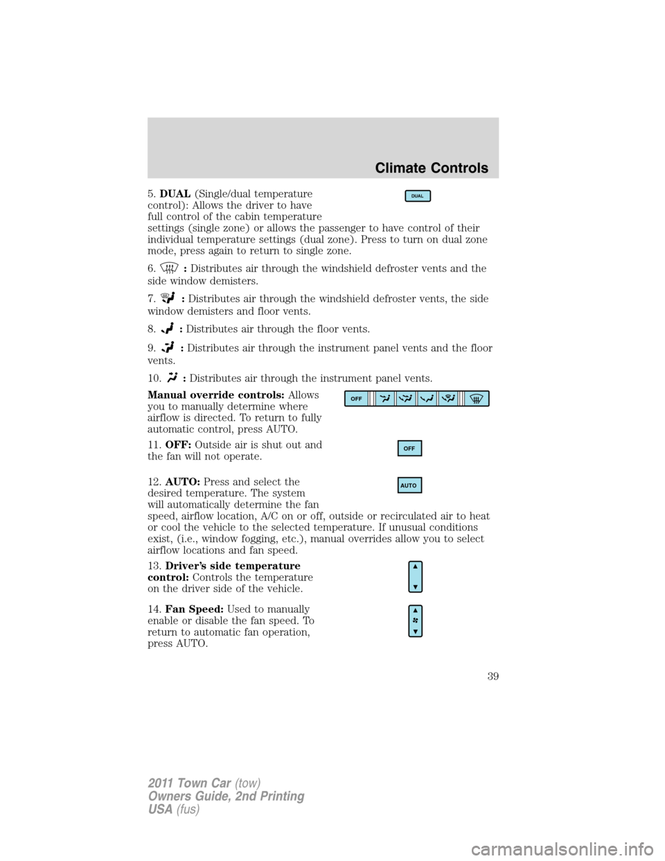
5.DUAL(Single/dual temperature
control): Allows the driver to have
full control of the cabin temperature
settings (single zone) or allows the passenger to have control of their
individual temperature settings (dual zone). Press to turn on dual zone
mode, press again to return to single zone.
6.
:Distributes air through the windshield defroster vents and the
side window demisters.
7.
:Distributes air through the windshield defroster vents, the side
window demisters and floor vents.
8.
:Distributes air through the floor vents.
9.
:Distributes air through the instrument panel vents and the floor
vents.
10.
:Distributes air through the instrument panel vents.
Manual override controls:Allows
you to manually determine where
airflow is directed. To return to fully
automatic control, press AUTO.
11.OFF:Outside air is shut out and
the fan will not operate.
12.AUTO:Press and select the
desired temperature. The system
will automatically determine the fan
speed, airflow location, A/C on or off, outside or recirculated air to heat
or cool the vehicle to the selected temperature. If unusual conditions
exist, (i.e., window fogging, etc.), manual overrides allow you to select
airflow locations and fan speed.
13.Driver’s side temperature
control:Controls the temperature
on the driver side of the vehicle.
14.Fan Speed:Used to manually
enable or disable the fan speed. To
return to automatic fan operation,
press AUTO.
DUAL
OFF
OFF
AUTO
Climate Controls
39
2011 Town Car(tow)
Owners Guide, 2nd Printing
USA(fus)
Page 40 of 306
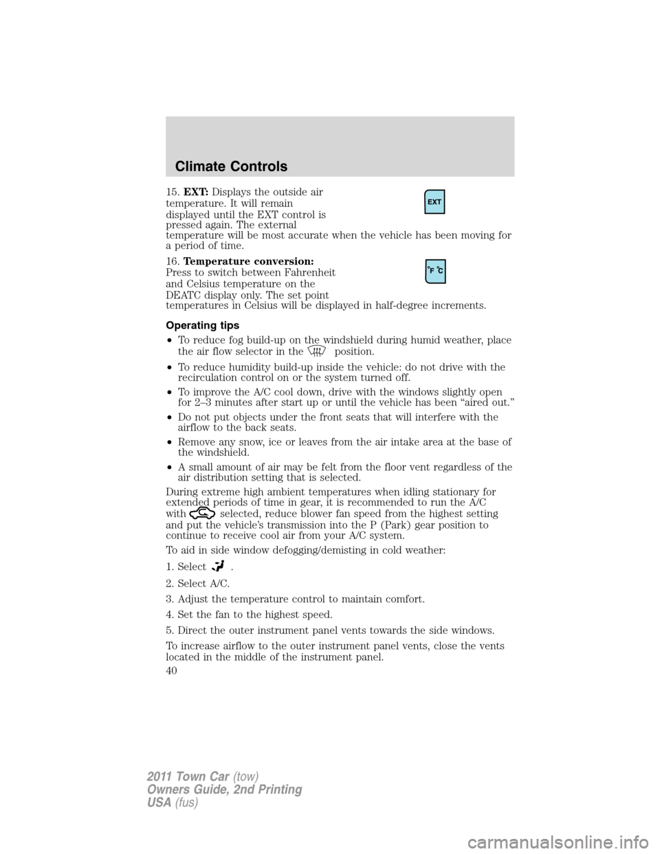
15.EXT:Displays the outside air
temperature. It will remain
displayed until the EXT control is
pressed again. The external
temperature will be most accurate when the vehicle has been moving for
a period of time.
16.Temperature conversion:
Press to switch between Fahrenheit
and Celsius temperature on the
DEATC display only. The set point
temperatures in Celsius will be displayed in half-degree increments.
Operating tips
•To reduce fog build-up on the windshield during humid weather, place
the air flow selector in the
position.
•To reduce humidity build-up inside the vehicle: do not drive with the
recirculation control on or the system turned off.
•To improve the A/C cool down, drive with the windows slightly open
for 2–3 minutes after start up or until the vehicle has been “aired out.”
•Do not put objects under the front seats that will interfere with the
airflow to the back seats.
•Remove any snow, ice or leaves from the air intake area at the base of
the windshield.
•A small amount of air may be felt from the floor vent regardless of the
air distribution setting that is selected.
During extreme high ambient temperatures when idling stationary for
extended periods of time in gear, it is recommended to run the A/C
with
selected, reduce blower fan speed from the highest setting
and put the vehicle’s transmission into the P (Park) gear position to
continue to receive cool air from your A/C system.
To aid in side window defogging/demisting in cold weather:
1. Select
.
2. Select A/C.
3. Adjust the temperature control to maintain comfort.
4. Set the fan to the highest speed.
5. Direct the outer instrument panel vents towards the side windows.
To increase airflow to the outer instrument panel vents, close the vents
located in the middle of the instrument panel.
Climate Controls
40
2011 Town Car(tow)
Owners Guide, 2nd Printing
USA(fus)
Page 41 of 306
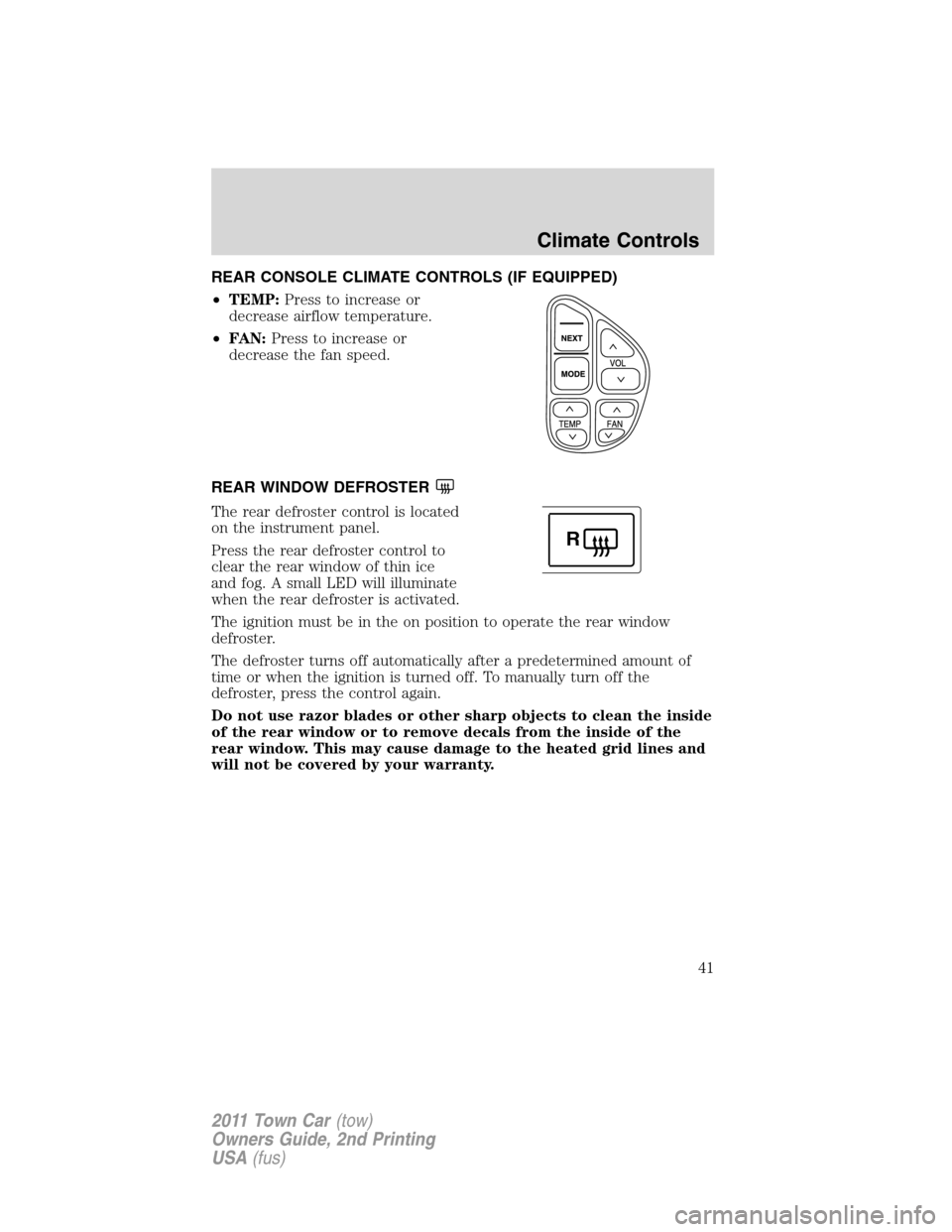
REAR CONSOLE CLIMATE CONTROLS (IF EQUIPPED)
•TEMP:Press to increase or
decrease airflow temperature.
•FAN:Press to increase or
decrease the fan speed.
REAR WINDOW DEFROSTER
The rear defroster control is located
on the instrument panel.
Press the rear defroster control to
clear the rear window of thin ice
and fog. A small LED will illuminate
when the rear defroster is activated.
The ignition must be in the on position to operate the rear window
defroster.
The defroster turns off automatically after a predetermined amount of
time or when the ignition is turned off. To manually turn off the
defroster, press the control again.
Do not use razor blades or other sharp objects to clean the inside
of the rear window or to remove decals from the inside of the
rear window. This may cause damage to the heated grid lines and
will not be covered by your warranty.
R
Climate Controls
41
2011 Town Car(tow)
Owners Guide, 2nd Printing
USA(fus)
Page 47 of 306
BULB REPLACEMENT
Lamp assembly condensation
Exterior lamps are vented to accommodate normal changes in pressure.
Condensation can be a natural by-product of this design. When moist air
enters the lamp assembly through the vents, there is a possibility that
condensation can occur when the temperature is cold. When normal
condensation occurs, a thin film of mist can form on the interior of the
lens. The thin mist eventually clears and exits through the vents during
normal operation. Clearing time may take as long as 48 hours under dry
weather conditions.
Examples of acceptable condensation are:
•Presence of thin mist (no streaks, drip marks or droplets)
•Fine mist covers less than 50% of the lens
Examples of unacceptable moisture (usually caused by a lamp water
leak) are:
•Water puddle inside the lamp
•Large water droplets, drip marks or streaks present on the interior of
the lens
Take your vehicle to a dealer for service if any of the above conditions of
unacceptable moisture are present.
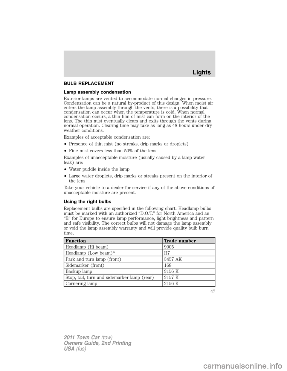
Using the right bulbs
Replacement bulbs are specified in the following chart. Headlamp bulbs
must be marked with an authorized “D.O.T.” for North America and an
“E” for Europe to ensure lamp performance, light brightness and pattern
and safe visibility. The correct bulbs will not damage the lamp assembly
or void the lamp assembly warranty and will provide quality bulb burn
time.
Function Trade number
Headlamp (Hi beam) 9005
Headlamp (Low beam)* H7
Park and turn lamp (front) 3457 AK
Sidemarker (front) 168
Backup lamp 3156 K
Stop, tail, turn and sidemarker lamp (rear) 3157 K
Cornering lamp 3156 K
Lights
47
2011 Town Car(tow)
Owners Guide, 2nd Printing
USA(fus)
Page 50 of 306
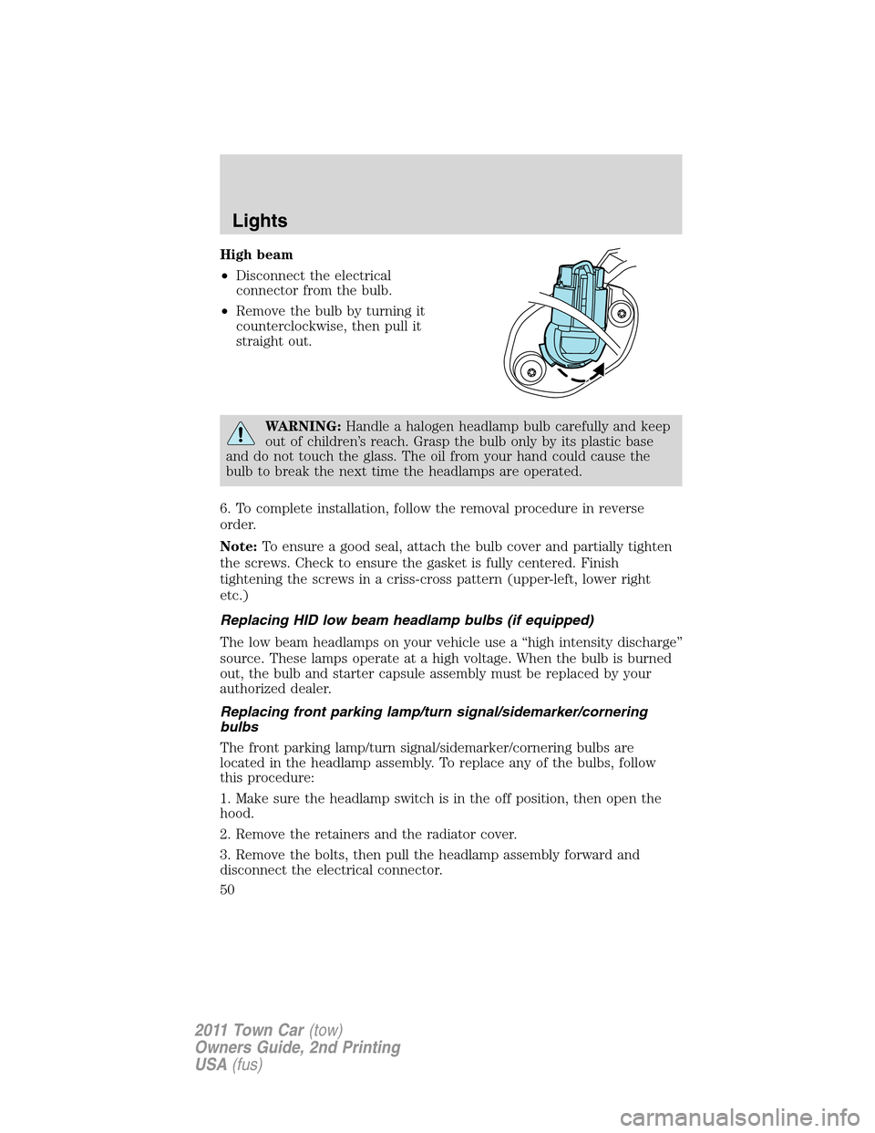
High beam
•Disconnect the electrical
connector from the bulb.
•Remove the bulb by turning it
counterclockwise, then pull it
straight out.
WARNING:Handle a halogen headlamp bulb carefully and keep
out of children’s reach. Grasp the bulb only by its plastic base
and do not touch the glass. The oil from your hand could cause the
bulb to break the next time the headlamps are operated.
6. To complete installation, follow the removal procedure in reverse
order.
Note:To ensure a good seal, attach the bulb cover and partially tighten
the screws. Check to ensure the gasket is fully centered. Finish
tightening the screws in a criss-cross pattern (upper-left, lower right
etc.)
Replacing HID low beam headlamp bulbs (if equipped)
The low beam headlamps on your vehicle use a “high intensity discharge”
source. These lamps operate at a high voltage. When the bulb is burned
out, the bulb and starter capsule assembly must be replaced by your
authorized dealer.
Replacing front parking lamp/turn signal/sidemarker/cornering
bulbs
The front parking lamp/turn signal/sidemarker/cornering bulbs are
located in the headlamp assembly. To replace any of the bulbs, follow
this procedure:
1. Make sure the headlamp switch is in the off position, then open the
hood.
2. Remove the retainers and the radiator cover.
3. Remove the bolts, then pull the headlamp assembly forward and
disconnect the electrical connector.
Lights
50
2011 Town Car(tow)
Owners Guide, 2nd Printing
USA(fus)
Page 56 of 306
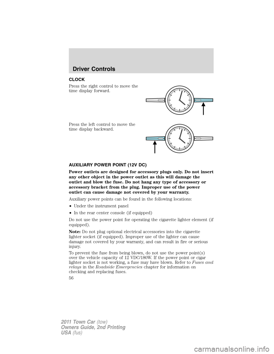
CLOCK
Press the right control to move the
time display forward.
Press the left control to move the
time display backward.
AUXILIARY POWER POINT (12V DC)
Power outlets are designed for accessory plugs only. Do not insert
any other object in the power outlet as this will damage the
outlet and blow the fuse. Do not hang any type of accessory or
accessory bracket from the plug. Improper use of the power
outlet can cause damage not covered by your warranty.
Auxiliary power points can be found in the following locations:
•Under the instrument panel
•In the rear center console (if equipped)
Do not use the power point for operating the cigarette lighter element (if
equipped).
Note:Do not plug optional electrical accessories into the cigarette
lighter socket (if equipped). Improper use of the lighter can cause
damage not covered by your warranty, and can result in fire or serious
injury.
To prevent the fuse from being blown, do not use the power point(s)
over the vehicle capacity of 12 VDC/180W. If the power point or cigar
lighter socket is not working, a fuse may have blown. Refer toFuses and
relaysin theRoadside Emergencieschapter for information on
checking and replacing fuses.
Driver Controls
56
2011 Town Car(tow)
Owners Guide, 2nd Printing
USA(fus)