LOTUS ELISE 2005 Owners Manual
Manufacturer: LOTUS, Model Year: 2005, Model line: ELISE, Model: LOTUS ELISE 2005Pages: 205, PDF Size: 4.51 MB
Page 141 of 205
Headlamp AlignmentThe headlamps of your Elise were correctly adjusted during
the manufacture of the car, and should only require subsequent
adjustment if the headlamp assembly or front body is disturbed.
Simply replacing the bulb will not affect alignment. Incorrectly adjusted headlamps can cause poor lighting performance or dazzle to oncoming traf fic. Special headlamp setting equip
-
ment is required to correctly set the headlamps, such that only
qualified technicians using appropriate equipment should be
entrusted with this procedure:
1. Using beam setting equipment compatible with local regu
-
lations, position the machine between 300 and 700mm in
front of the LH headlamp, and parallel with the two headlamp
units using the sight bar or similar device dependent on the machine design, to ensure cross car match. Use the guides provided on the machine to ensure the correct height and
lateral setting.
2. Switch on the headlamp low beams (uppermost lamps) and check the lateral beam alignment. The ‘knee point’ of the beam cut off line must lie within a tolerance of 2% to the pas
-
senger side, and 0%. Check the vertical alignment of the low beam which must lie within a tolerance of - 0.5% and -2%.
Electrical
139
oh_croft_InD.indd 13920/05/2004 07:59:15ProCarManuals.com
Page 142 of 205
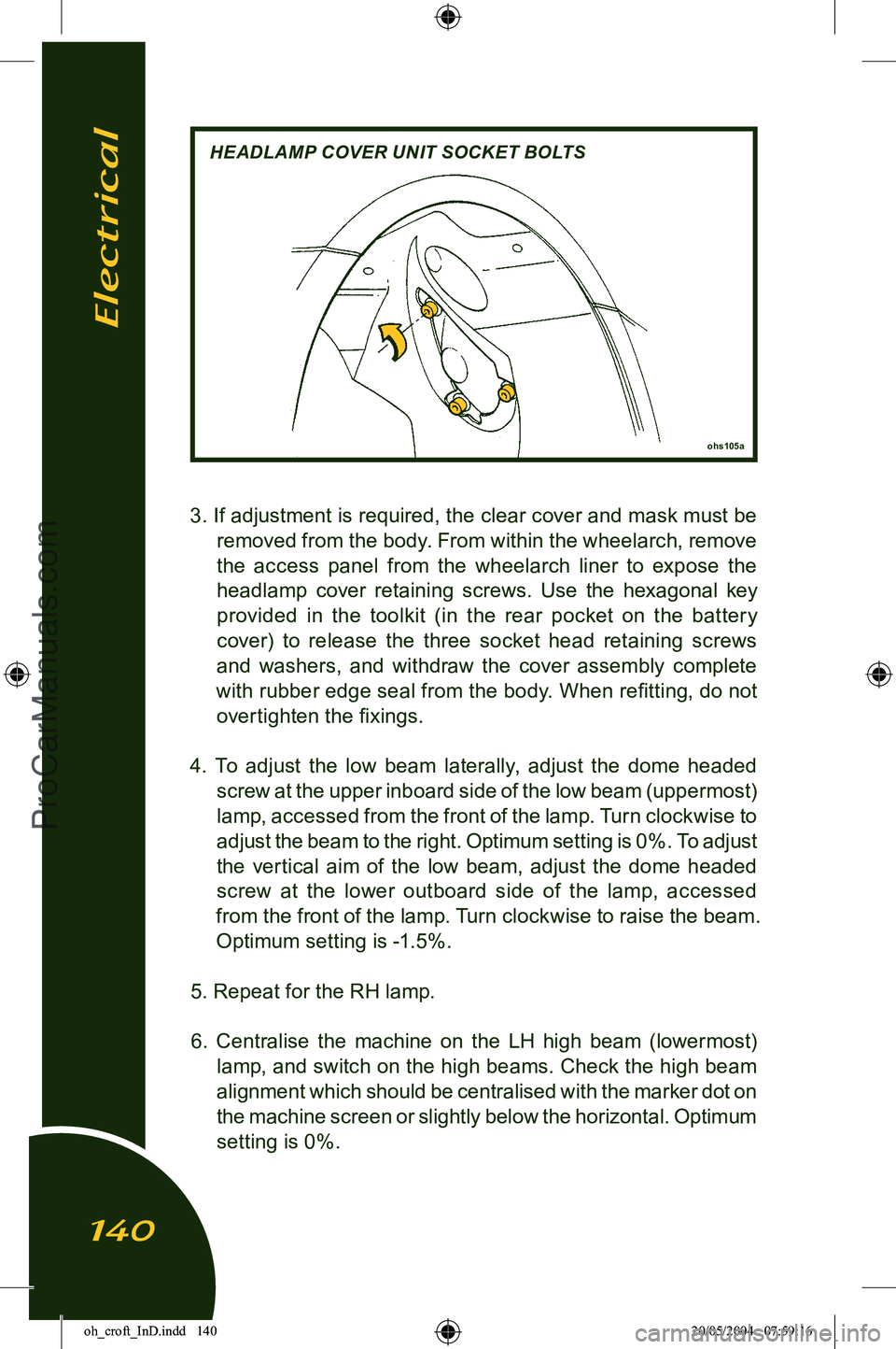
3. If adjustment is required, the clear cover and mask must be removed from the body. From within the wheelarch, remove
the access panel from the wheelarch liner to expose the
headlamp cover retaining screws. Use the hexagonal key provided in the toolkit (in the rear pocket on the batter y
cover) to release the three socket head retaining screws and washers, and withdraw the cover assembly complete
with rubber edge seal from the body. When refitting, do not overtighten the fixings.
4. To adjust the low beam laterally, adjust the dome headed screw at the upper inboard side of the low beam (uppermost)
lamp, accessed from the front of the lamp. Turn clockwise to
adjust the beam to the right. Optimum setting is 0%. To adjust
the vertical aim of the low beam, adjust the dome headed screw at the lower outboard side of the lamp, accessed
from the front of the lamp. Turn clockwise to raise the beam.
Optimum setting is -1.5%.
5. Repeat for the RH lamp. 6. Centralise the machine on the LH high beam (lowermost) lamp, and switch on the high beams. Check the high beam
alignment which should be centralised with the marker dot on
the machine screen or slightly below the horizontal. Optimum
setting is 0%.
ohs105a
HEADLAMP COVER UNIT SOCKET BOLTS
Electrical
140
oh_croft_InD.indd 14020/05/2004 07:59:16ProCarManuals.com
Page 143 of 205
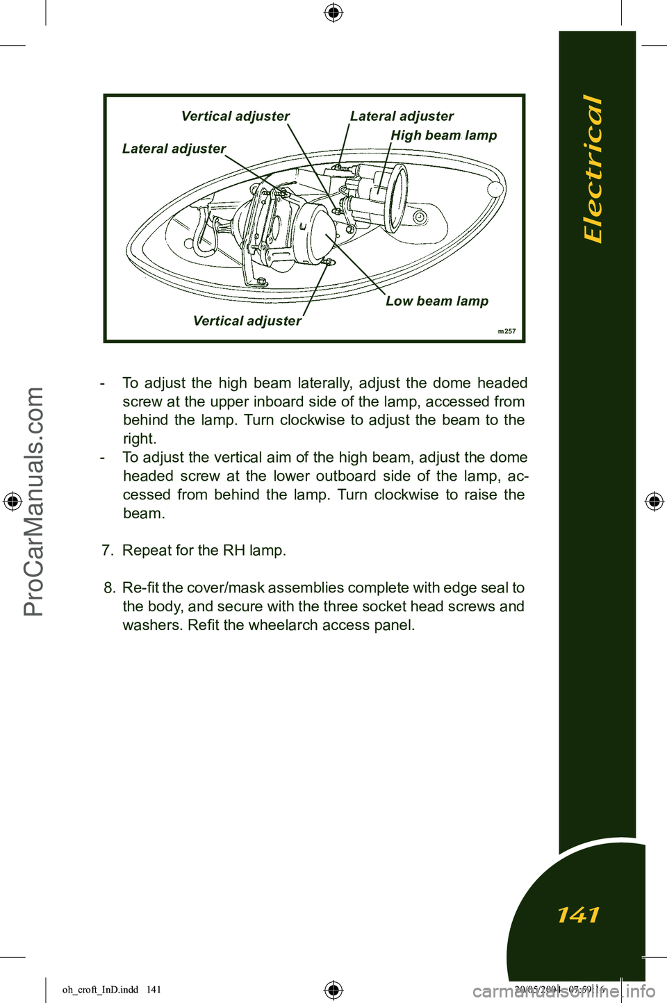
- To adjust the high beam laterally, adjust the dome headed screw at the upper inboard side of the lamp, accessed from behind the lamp. Turn clockwise to adjust the beam to the
right.
- To adjust the vertical aim of the high beam, adjust the dome headed screw at the lower outboard side of the lamp, ac
-
cessed from behind the lamp. Turn clockwise to raise the
beam.
7. Repeat for the RH lamp. 8. Re-fit the cover/mask assemblies complete with edge seal to the body, and secure with the three socket head screws and
washers. Refit the wheelarch access panel.
m257
Vertical adjuster
Lateral adjuster Lateral adjuster
High beam lamp
Vertical adjuster
Low beam lamp
Electrical
141
oh_croft_InD.indd 14120/05/2004 07:59:16ProCarManuals.com
Page 144 of 205
BULB REPLACEMENT
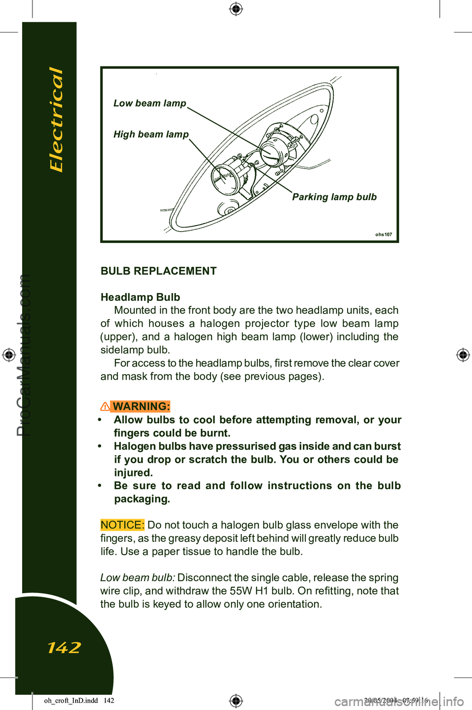
Headlamp BulbMounted in the front body are the two headlamp units, each
of which houses a halogen projector type low beam lamp
(upper), and a halogen high beam lamp (lower) including the sidelamp bulb. For access to the headlamp bulbs, first remove the clear cover
and mask from the body (see previous pages).
WARNING:
• Allow bulbs to cool before attempting removal, or your fingers could be burnt.
• Halogen bulbs have pressurised gas inside and can burst if you drop or scratch the bulb. You or others could be
injured.
• Be sure to read and follow instructions on the bulb
packaging.
NOTICE: Do not touch a halogen bulb glass envelope with the
fingers, as the greasy deposit left behind will greatly reduce bulb life. Use a paper tissue to handle the bulb.
Low beam bulb: Disconnect the single cable, release the spring wire clip, and withdraw the 55W H1 bulb. On refitting, note that the bulb is keyed to allow only one orientation.
ohs107
Low beam lamp
High beam lamp
Parking lamp bulb
Electrical
142
oh_croft_InD.indd 14220/05/2004 07:59:16ProCarManuals.com
Page 145 of 205
High beam bulb: Disconnect the two cables from the bulb, re-
lease the spring wire clip, and withdraw the 55W H7 bulb. On re
-
fitting, note that the bulb is keyed to allow only one orientation.
Parking lamp: Twist the bulb holder counterclockwise to release
from the main beam lamp, and withdraw the bayonet fitting T4
W bulb.
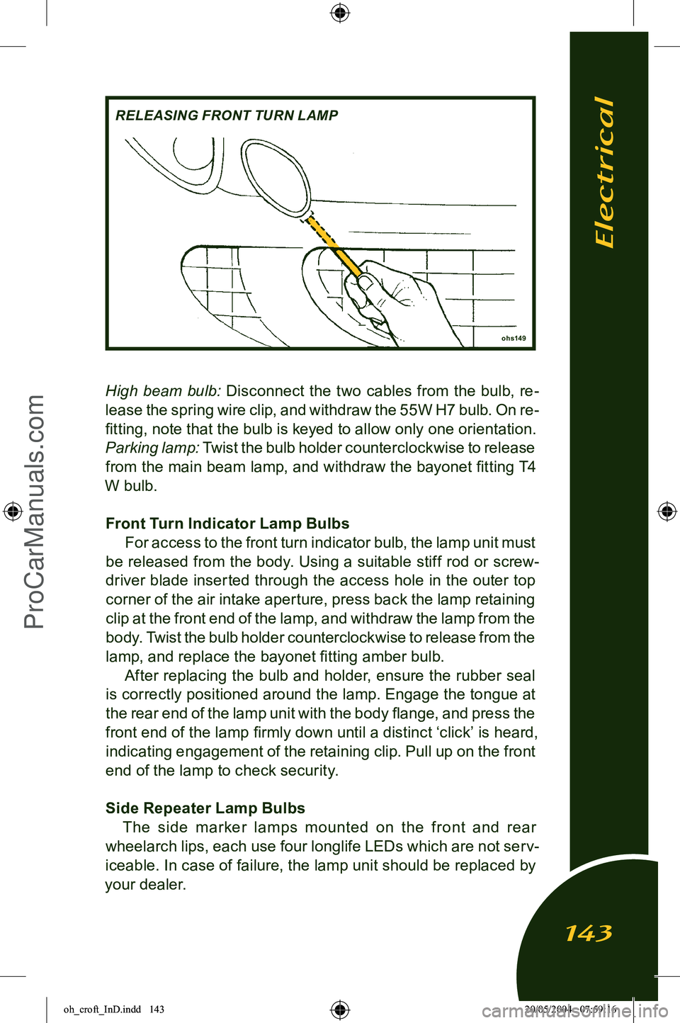
Front Turn Indicator Lamp Bulbs For access to the front turn indicator bulb, the lamp unit must
be released from the body. Using a suitable stiff rod or screw
-
driver blade inserted through the access hole in the outer top
corner of the air intake aperture, press back the lamp retaining
clip at the front end of the lamp, and withdraw the lamp from the body. Twist the bulb holder counterclockwise to release from the
lamp, and replace the bayonet fitting amber bulb. After replacing the bulb and holder, ensure the rubber seal
is correctly positioned around the lamp. Engage the tongue at
the rear end of the lamp unit with the body flange, and press the
front end of the lamp firmly down until a distinct ‘click’ is heard, indicating engagement of the retaining clip. Pull up on the front
end of the lamp to check security.
Side Repeater Lamp Bulbs The side mar ker lamps mounted on the front and rear
wheelarch lips, each use four longlife LEDs which are not serv
-
iceable. In case of failure, the lamp unit should be replaced by
your dealer.
ohs149
RELEASING FRONT TURN LAMP
Electrical
143
oh_croft_InD.indd 14320/05/2004 07:59:16ProCarManuals.com
Page 146 of 205
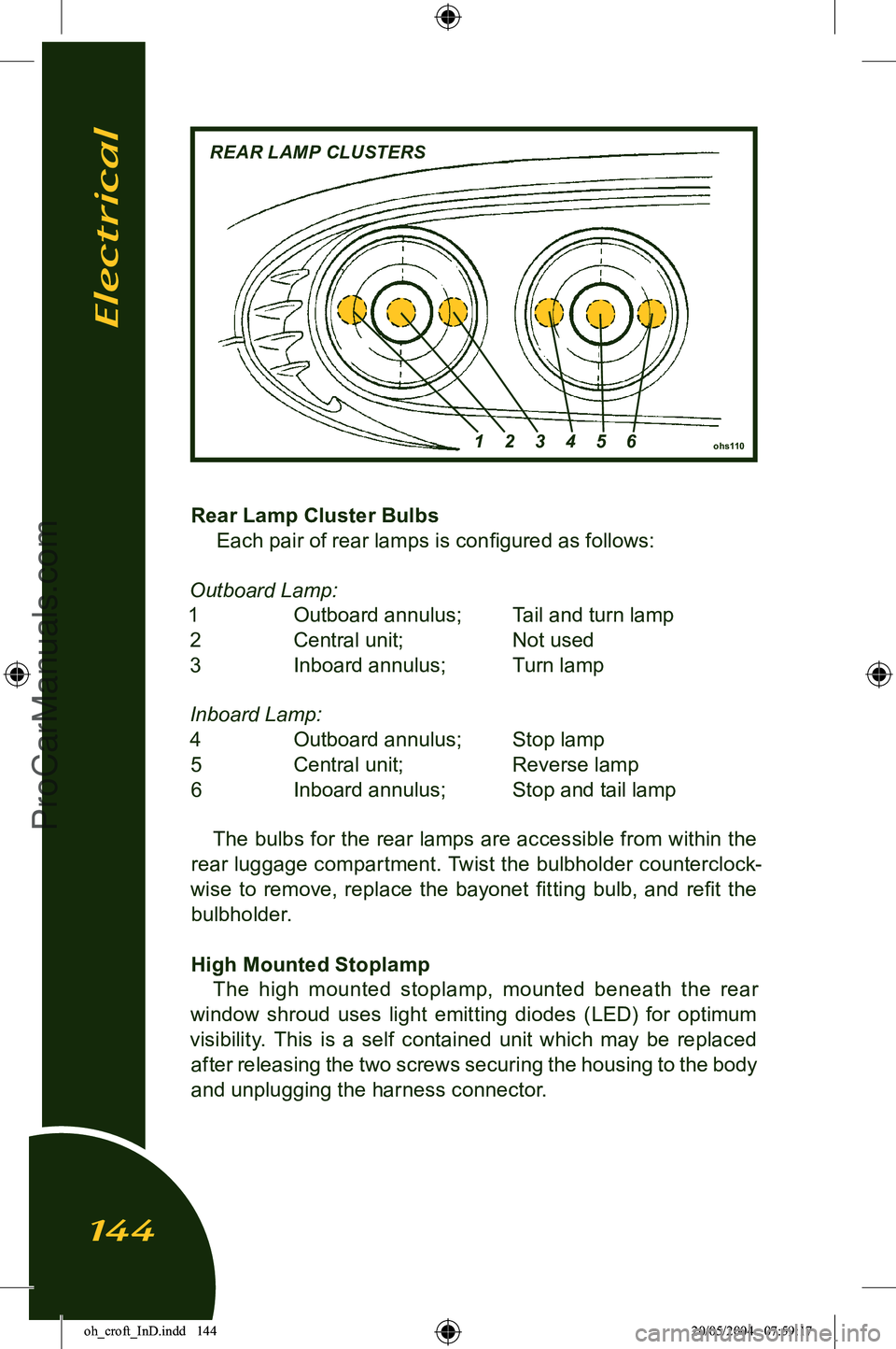
Rear Lamp Cluster BulbsEach pair of rear lamps is configured as follows:
Outboard Lamp:
1 Outboard annulus; Tail and turn lamp 2 Central unit; Not used
3 Inboard annulus; Turn lamp
Inboard Lamp: 4 Outboard annulus; Stop lamp 5 Central unit; Reverse lamp
6 Inboard annulus; Stop and tail lamp
The bulbs for the rear lamps are accessible from within the
rear luggage compartment. Twist the bulbholder counterclock
-
wise to remove, replace the bayonet fitting bulb, and refit the bulbholder.
High Mounted Stoplamp The high mounted stoplamp, mounted beneath the rear
window shroud uses light emitting diodes (LED) for optimum
visibility. This is a self contained unit which may be replaced after releasing the two screws securing the housing to the body
and unplugging the harness connector.
ohs110
REAR LAMP CLUSTERS
1 2 3 4 5 6
Electrical
144
oh_croft_InD.indd 14420/05/2004 07:59:17ProCarManuals.com
Page 147 of 205
Licence Plate Lamps To replace a bulb in a licence plate lamp, first remove the two
screws securing the lamp, and withdraw. Replace the festoon
bulb, and refit the lamp.
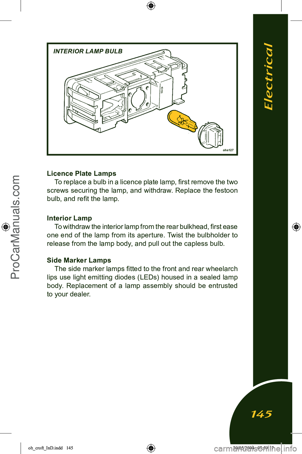
Interior Lamp To withdraw the interior lamp from the rear bulkhead, first ease
one end of the lamp from its aperture. Twist the bulbholder to release from the lamp body, and pull out the capless bulb.
Side Marker Lamps The side marker lamps fitted to the front and rear wheelarch
lips use light emitting diodes (LEDs) housed in a sealed lamp
body. Replacement of a lamp assembly should be entrusted
to your dealer.
ohs127
INTERIOR LAMP BULB
Electrical
145
oh_croft_InD.indd 14520/05/2004 07:59:17ProCarManuals.com
Page 148 of 205
LIFTING AND TOWING
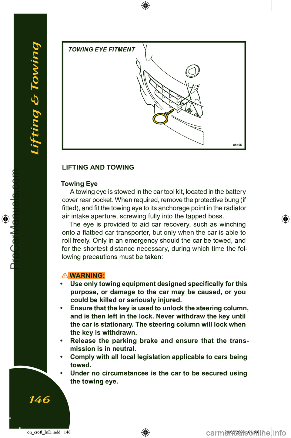
Towing Eye A towing eye is stowed in the car tool kit, located in the battery
cover rear pocket. When required, remove the protective bung (if
fitted), and fit the towing eye to its anchorage point in the radiator air intake aperture, screwing fully into the tapped boss.
The eye is provided to aid car recovery, such as winching
onto a flatbed car transporter, but only when the car is able to roll freely. Only in an emergency should the car be towed, and
for the shortest distance necessary, during which time the fol
-
lowing precautions must be taken:
WARNING:
• Use only towing equipment designed specifically for this purpose, or damage to the car may be caused, or you
could be killed or seriously injured.
• Ensure that the key is used to unlock the steering column, and is then left in the lock. Never withdraw the key until
the car is stationary. The steering column will lock when
the key is withdrawn.
• Release the parking brake and ensure that the trans
-
mission is in neutral.
• Comply with all local legislation applicable to cars being
towed.
• Under no circumstances is the car to be secured using
the towing eye.
ohs95
TOWING EYE FITMENT
Lifting & Towing
146
oh_croft_InD.indd 14620/05/2004 07:59:17ProCarManuals.com
Page 149 of 205
Towing a Trailer
WARNING:The Elise is not suitable for towing a trailer.
Car Tie-Down When moving a car by transporter or trailer, the car should be
secured only by chocking and strapping around the road wheels.
Attaching restraints around suspension linkages or chassis or body components may cause damage.
Lifting & Towing
147
oh_croft_InD.indd 14720/05/2004 07:59:17ProCarManuals.com
Page 150 of 205
Lifting Your Car
WARNING:
• Using a lifting jack can be dangerous. If the car falls off the jack, you or others could be seriously injured or killed.
NEVER get under a car when it is supported only by a
jack.
• Before raising the car with a jack: - Turn off the engine;
- Firmly apply the parking brake;
- Engage first or reverse gear;
- Securely chock all wheels not to be lifted.
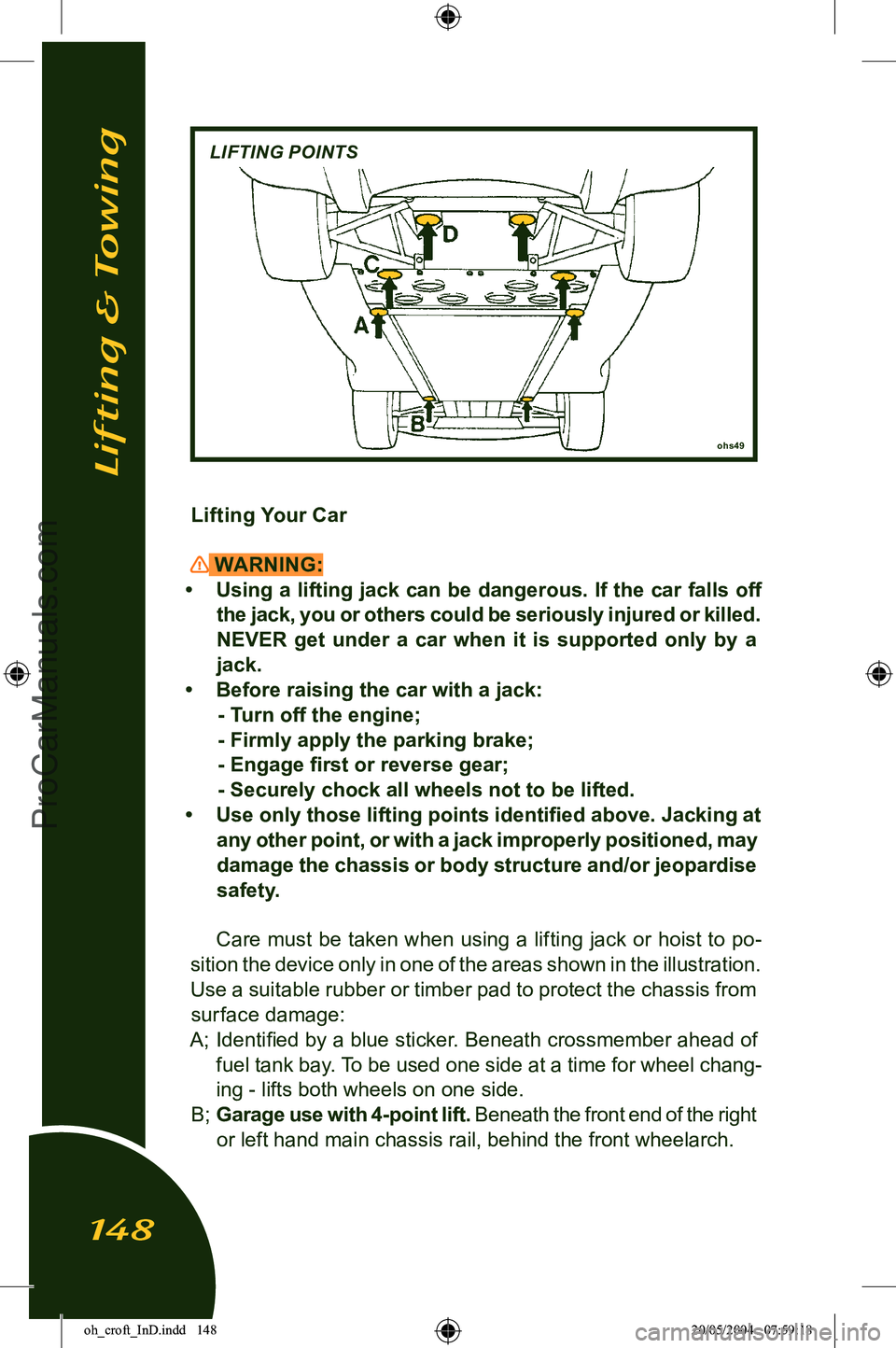
• Use only those lifting points identified above. Jacking at any other point, or with a jack improperly positioned, may
damage the chassis or body structure and/or jeopardise safety.
Care must be taken when using a lifting jack or hoist to po
-
sition the device only in one of the areas shown in the illustration.
Use a suitable rubber or timber pad to protect the chassis from
surface damage:
A; Identified by a blue sticker. Beneath crossmember ahead of fuel tank bay. To be used one side at a time for wheel chang
-
ing - lifts both wheels on one side.
B; Garage use with 4-point lift. Beneath the front end of the right
or left hand main chassis rail, behind the front wheelarch.
ohs49
LIFTING POINTS
Lifting & Towing
148
oh_croft_InD.indd 14820/05/2004 07:59:18ProCarManuals.com