stop LOTUS ELISE 2005 User Guide
[x] Cancel search | Manufacturer: LOTUS, Model Year: 2005, Model line: ELISE, Model: LOTUS ELISE 2005Pages: 205, PDF Size: 4.51 MB
Page 69 of 205
FootbrakeVentilated disc brakes are fitted to all four wheels of the
Elise. These are operated by separate front and rear hydraulic
circuits, supplied from a tandem master cylinder with vacuum
servo. Anti-lock control is provided by a microprocessor based
electro-hydraulic unit, integrated into the base braking system. The braking system is designed to provide good pedal feed
-
back, with efficient disc cooling to inhibit brake fade. With a
new car, or new brake system components, maximum braking
efficiency will be achieved if, for the first few hundred miles, needless heavy braking is avoided. Allow the brake pads and discs to ‘bed in’ fully before using the brakes to their full potential.
Pedal effort will reduce as the brakes are bedded in, and as they
are warmed from cold to normal working temperature. Note that
the hard grade pad material may give rise to a certain amount of brake noise under some conditions; such noise is not harmful
and does not affect the life or efficiency of the brakes.
WARNING:
• After driving through a ford, or a flooded road, some loss of braking response may be experienced until the brakes
have dried out. As soon as it is safe to do so after such an encounter, apply the brakes until normal operation
is restored. Failure to do so may result in an accident in
which you or others may be killed or seriously injured.
• The brake assistance servo uses vacuum supplied from the engine intake plenum, such that assistance is avail
-
able only when the engine is running. Never coast down
-
hill with the engine stopped. If this situation accidently arises, avoid repeated application of the brakes, or the
stored vacuum supply will be rapidly used up. Greater
pedal pressures will be required. This may adversely affect performance of the brakes which may result in an
accident in which you or others may be killed or seriously
injured.
Anti-lock Brake System The Anti-lock Brake System (ABS) is used to optimise brake
performance in extreme conditions and reduce the potential
for any wheel to lock up. Under most conditions, the maximum braking force is provided by a wheel which is rotating at about
90% of road speed. Apart from the likelihood of increasing the
Driving Controls
67
oh_croft_InD.indd 6720/05/2004 07:58:57ProCarManuals.com
Page 70 of 205
stopping distance, a locked wheel provides little or no steering
force, such that with both front wheels locked, movement of the steering wheel has no effect on car direction. With the anti-lock
system, even panic braking results in controlled deceleration and the retention of steering response. ABS is especially ad
-
vantageous when braking on slippery road surfaces and in bad driving conditions, but it is important to realise that the ABS
cannot increase the friction level at the road surface, but can only make optimum use of the grip available.
WARNING: When driving in adverse weather, or on poor road sur
-
faces, always be alert to the possibility of slippery condi
-
tions and make the necessary allowance for increased stop
-
ping distances. Failure to do so may result in an accident in which you or others may be killed or seriously injured.
Normal braking, controlled by the pressure applied to the
brake pedal, occurs when the road conditions allow for decel
-
eration to be achieved without danger of wheel lock. The relative
speeds of the four wheels are continuously monitored by the
ABS when the brakes are applied, and if one or more wheels begin to lock, the brake pressure to that wheel(s) is modulated
by the ABS to help keep the wheel rotating and provide the
maximum controlled braking force. The wheels may appear
to lock momentarily as the wheel speed rapidly changes, and some tire noise (intermittent screeching) may be heard which is normal and will vary with road and tire conditions. Note that the
ABS does not function at speeds below 5 mph (7 km/h). When the ABS is activated, the driver is will feel a ‘pulsing’
sensation at the brake pedal as the fluid pressure is modulated, and also by audible clicking sounds. These signals indicate to
the driver that maximum braking is occuring, and that driving style should be modified to suit the conditions.
The minimum stopping distance is achieved by applying the
brakes firmly and steadily, and allowing the ABS to modulate
hydraulic pressure. The driver should not attempt to emulate
this process by ‘pumping’ the brake pedal, as modulation at the pedal will treat all four wheels similarly, rather than the individual
wheel control allowed by the electronics. An ABS tell tale lamp in the instrument panel is provided
to warn of any problems in the system and to indicate that the
Driving Controls
68
oh_croft_InD.indd 6820/05/2004 07:58:57ProCarManuals.com
Page 71 of 205
integral self diagnostics have switched out the anti-lock function.
See ‘ABS tell tale lamp’.
WARNING:
• The increased control that ABS provides should not induce you to take more risks with your safety. ABS will
not prevent a skid caused by abrupt steering movements,
or attempting to corner too quickly.
• Always maintain a safe following distance from other cars relative to the road surface and weather conditions.
Obey all traffic laws.
• Risk of accidents due to inappropriate speed cannot be reduced even by ABS. The driver is responsible for the
judgement of safe speed.
• The control unit of the ABS is set for standard tire size. If non-standard Tires are fitted, the control unit may mis-
interpret the speed of the car, because of the variant data
it receives from the wheel speed sensors. Fitting non standard tires would seriously affect the performance of
your ABS.
• The amber ABS tell tale in the instrument panel should light for about 4 seconds following ignition switch on, and
then go out. If the lamp remains lit, or comes on whilst driving, a fault in the anti-lock brake system is indicated.
The base brake system will continue to operate normally,
but without ABS. The car can be driven but should be
checked and repaired at the earliest opportunity.
• Activation of the ABS will vary according to the level of grip available at the Tires. On dry surfaces, activation
will occur only with a high pedal pressure. On slippery
surfaces, only a low pressure will be needed.
• On loose or uneven surfaces, such as gravel or snow, a car with ABS may need a longer stopping distance. Allow
a greater distance between cars in these conditions.
Driving Controls
69
oh_croft_InD.indd 6920/05/2004 07:58:57ProCarManuals.com
Page 74 of 205
STARTING PROCEDURE & ENGINE BREAK-IN
WARNING:CARBON MONOXIDE - Be aware of the danger of carbon
monoxide! Never run the engine in an enclosed space. The
exhaust gases contain carbon monoxide, a deadly gas
which is particularly dangerous, as being colourless odour
-
less and tasteless, its presence is very difficult to detect.
Before starting the engine, always check that the parking
brake is firmly applied, the transmission is in neutral, and as
an extra precaution, depress the clutch pedal. Switch off any
unnecessary electrical loads.
Starting a Cold or Warm Engine
The fuel injection and engine management system controls fuel delivery and engine settings under all normal operating conditions.
i) Insert the key into the steering lock/ignition switch and turn to
position ‘l’ to unlock the column. Before turning on the igni
-
tion; if the security tell tale in the tachometer face is flashing, mobilise the engine by pressing once, and for a full second,
the larger of the two buttons on the transmitter fob.
ii) Turn the key to position ‘II’ to switch on the ignition, and pause
for a moment to allow the fuel system to prime.
iii) Depress the clutch pedal as a precaution, and without moving
the accelerator, press the ‘Start’ button at the left hand end of
the dashboard to engage the starter motor. Release the button
as soon as the engine starts. Allow a cold engine to idle for
10 seconds before driving off, but if ambient temperatures are below freezing, allow the engine and screen heating systems
to warm up for a few minutes before driving.
iv) If the engine fails to start within 15 seconds, stop cranking
and pause for 10 seconds before a second attempt.
v) If further efforts are unsuccessful, contact your dealer or seek
other expert help.
WARNING:
An unattended car with a running engine is potentially
hazardous. Turn off the engine before leaving the car.
Starting & Engine Break-In
72
oh_croft_InD.indd 7220/05/2004 07:58:58ProCarManuals.com
Page 78 of 205
Methanol - Do not use gasolines containing methanol (wood
alcohol). Use of this type of alcohol can result in car performance deterioration and damage to critical parts in the fuel system. Fuel
system damage and car performance problems, resulting from
the use of gasolines containing methanol, may not be covered by your car warranty.
Fuels Containing MMT - Some North American fuels contain methylcyclopentadienyl manganese tricarbonyl (MMT), which
is an octane enhancing additive. Such fuels may damage the
emission control system and are NOT recommended.
Diesel
- The Lotus Elise will not operate on diesel fuel.
Fuel Filling
WARNING:
• Gasoline and its attendant fumes are highly explosive. You can be burned or seriously injured when handling
fuel. Before stopping at a filling station, switch off mobile phones and other electronic equipment, ensure that all
cigarettes are extinguished and that no naked flames or
other potential ignition sources are present. Switch off
the engine before refuelling.
• Remove the filler cap slowly to allow any pressure to bleed off gradually. Hasty removal may result in a small amount
of fuel spray with a possible health or fire hazard. External Operations
76
oh_croft_InD.indd 7620/05/2004 07:58:59ProCarManuals.com
Page 101 of 205
ohs149
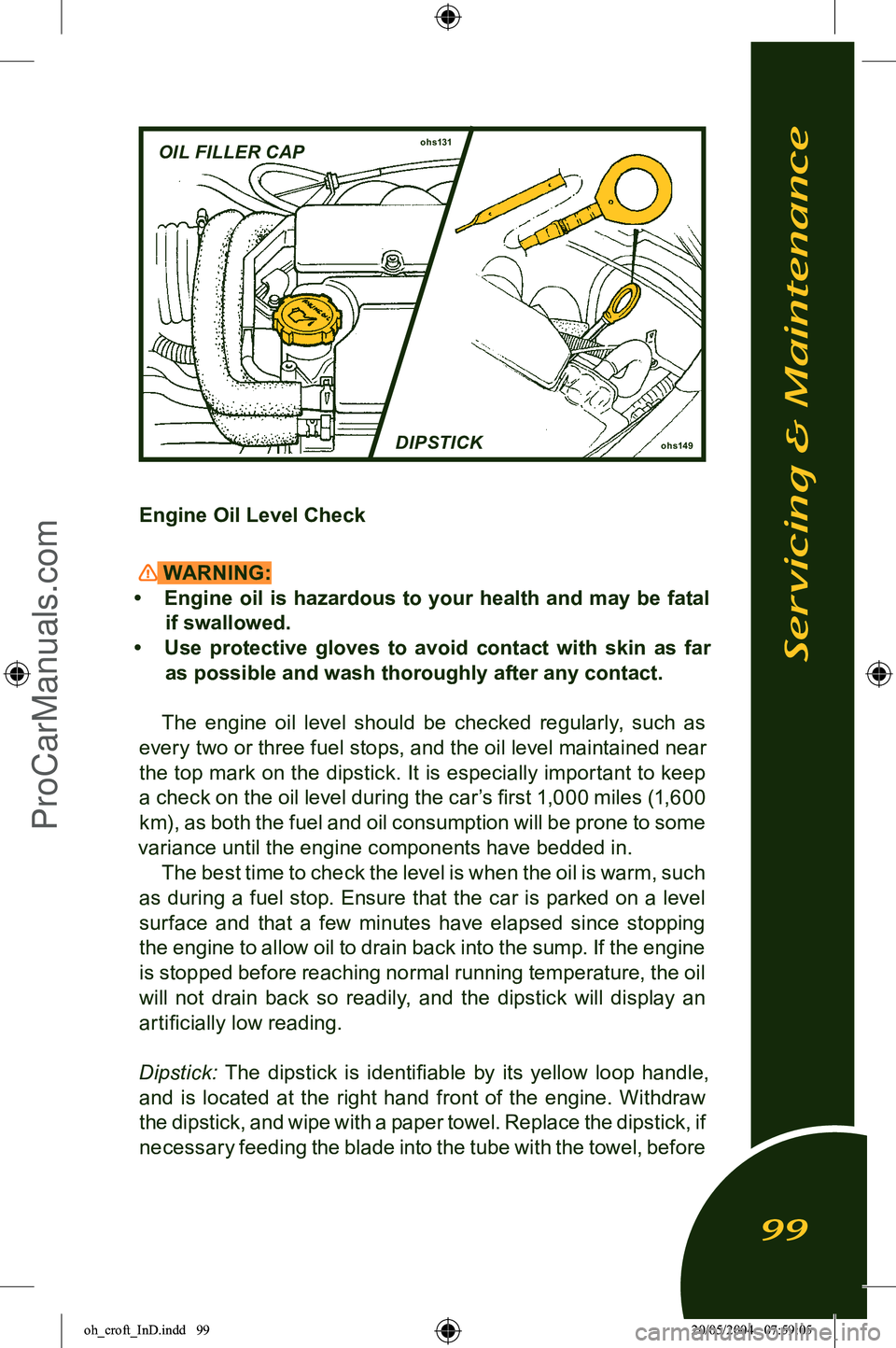
OIL FILLER CAPohs131
DIPSTICK
Engine Oil Level Check
WARNING:
• Engine oil is hazardous to your health and may be fatal
if swallowed.
• Use protective gloves to avoid contact with skin as far as possible and wash thoroughly after any contact.
The engine oil level should be checked regularly, such as
every two or three fuel stops, and the oil level maintained near
the top mark on the dipstick. It is especially important to keep a check on the oil level during the car’s first 1,000 miles (1,600
km), as both the fuel and oil consumption will be prone to some
variance until the engine components have bedded in. The best time to check the level is when the oil is warm, such
as during a fuel stop. Ensure that the car is parked on a level
surface and that a few minutes have elapsed since stopping
the engine to allow oil to drain back into the sump. If the engine is stopped before reaching normal running temperature, the oil
will not drain back so readily, and the dipstick will display an artificially low reading.
Dipstick: The dipstick is identifiable by its yellow loop handle,
and is located at the right hand front of the engine. Withdraw
the dipstick, and wipe with a paper towel. Replace the dipstick, if necessary feeding the blade into the tube with the towel, before
Servicing & Maintenance
99
oh_croft_InD.indd 9920/05/2004 07:59:05ProCarManuals.com
Page 123 of 205
characteristics and climates.
Traction - AA, A, B, C: The traction grades, from highest to lowest are: A A, A, B, and C. They represent the tires ability to stop on wet pavement as measured under con
-
trolled conditions on specified government test surfaces of asphalt and concrete. A tire marked ‘C’ may have poor
traction performance.
WARNING: The traction grade assigned to this tire is based
on braking (straight ahead) traction tests and does
not include acceleration, cornering, hydroplaning, or
peak traction characteristics.
Temperature - A, B, C: The temperature grades are A (the highest), B, and C, representing the tire’s resistance to the generation of heat and its ability to dissipate heat when
tested under controlled conditions on a specified indoor laboratory test wheel. Sustained high temperature can cause the material of the tire to degenerate and reduce tire
life, and excessive temperature can lead to sudden tire fail
-
ure. The grade ‘C’ corresponds to a level of performance
which all passenger car Tires must meet under Federal Motor Car Safety Standard No. 109. Grades ‘B’ and ‘A’ represent higher levels of performance on the laboratory
test wheel than the minimum required by law.
WARNING: The temperature grade for this tire is established
for a tire that is properly inflated and not overloaded. Excessive speed, underinflation, or excessive load
-
ing, either separately or in combination, can cause
heat buildup and possible tire failure.
These grades are moulded onto the sidewalls of pas
-
senger car tires. All passenger car tires must conform to Federal safety requirements in addition to these grades.
Tire Placard/Label The tire and loading Information label stuck on the
driver’s door jamb specifies the correct size and pres
-
Tires & Wheels
121
oh_croft_InD.indd 12120/05/2004 07:59:11ProCarManuals.com
Page 138 of 205
WARNING:Replacing a fuse with one which has a higher rating may
cause extensive damage to the electrical system and pos
-
sibly cause a fire. If a fuse of the correct rating is not avail
-
able, use one of a lower rating as a temporary measure.
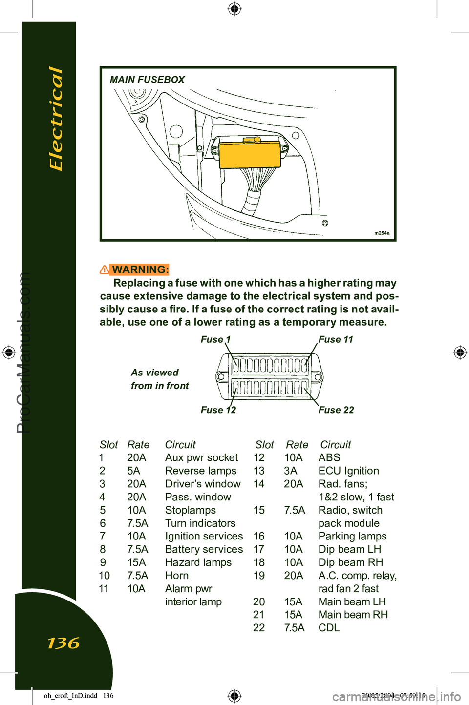
Slot
Rate Circuit Slot Rate Circuit
1 20A Aux pwr socket 12 10A ABS 2 5A Reverse lamps 13 3A ECU Ignition
3 20A Driver’s window 14 20A Rad. fans;
4 20A Pass. window 1&2 slow, 1 fast 5 10A Stoplamps 15 7.5A Radio, switch6 7.5A Turn indicators pack module
7 10A Ignition services 16 10A Parking lamps
8 7.5A Battery services 17 10A Dip beam LH9 15A Hazard lamps 18 10A Dip beam RH
10 7.5A Horn 19 20A A.C. comp. relay,
11 10A Alarm pwr rad fan 2 fast interior lamp 20 15A Main beam LH
21 15A Main beam RH
22 7.5A CDL
m254a
MAIN FUSEBOX
Fuse 1Fuse 11
Fuse 12 Fuse 22
As viewed
from in front
Electrical
136
oh_croft_InD.indd 13620/05/2004 07:59:15ProCarManuals.com
Page 139 of 205
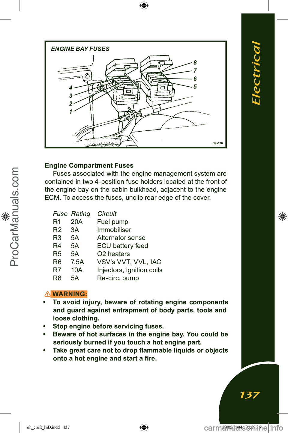
Engine Compartment FusesFuses associated with the engine management system are
contained in two 4-position fuse holders located at the front of
the engine bay on the cabin bulkhead, adjacent to the engine ECM. To access the fuses, unclip rear edge of the cover.
Fuse Rating CircuitR1 20A Fuel pump
R2 3A Immobiliser
R3 5A Alternator sense
R4 5A ECU battery feed
R5 5A O2 heaters
R6 7.5A VSV's V VT, V VL, IAC
R7 10A Injectors, ignition coils
R8 5A Re-circ. pump
WARNING:
• To avoid injury, beware of rotating engine components and guard against entrapment of body parts, tools and
loose clothing.
• Stop engine before servicing fuses.
• Beware of hot surfaces in the engine bay. You could be seriously burned if you touch a hot engine part.
• Take great care not to drop flammable liquids or objects onto a hot engine and start a fire.
ohs136
ENGINE BAY FUSES
4
3
2
1
8
7
6
5
Electrical
137
oh_croft_InD.indd 13720/05/2004 07:59:15ProCarManuals.com
Page 146 of 205
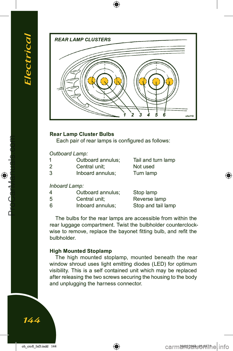
Rear Lamp Cluster BulbsEach pair of rear lamps is configured as follows:
Outboard Lamp:
1 Outboard annulus; Tail and turn lamp 2 Central unit; Not used
3 Inboard annulus; Turn lamp
Inboard Lamp: 4 Outboard annulus; Stop lamp 5 Central unit; Reverse lamp
6 Inboard annulus; Stop and tail lamp
The bulbs for the rear lamps are accessible from within the
rear luggage compartment. Twist the bulbholder counterclock
-
wise to remove, replace the bayonet fitting bulb, and refit the bulbholder.
High Mounted Stoplamp The high mounted stoplamp, mounted beneath the rear
window shroud uses light emitting diodes (LED) for optimum
visibility. This is a self contained unit which may be replaced after releasing the two screws securing the housing to the body
and unplugging the harness connector.
ohs110
REAR LAMP CLUSTERS
1 2 3 4 5 6
Electrical
144
oh_croft_InD.indd 14420/05/2004 07:59:17ProCarManuals.com