instrument panel LOTUS ELISE 2005 Owners Manual
[x] Cancel search | Manufacturer: LOTUS, Model Year: 2005, Model line: ELISE, Model: LOTUS ELISE 2005Pages: 205, PDF Size: 4.51 MB
Page 4 of 205
8. INSTRUMENTS & SWITCHES
Ignition Switch/Steering Lock ..........................................
44
Engine Start Button .........................................................
45
Warning āTell Taleā Lamps ...............................................
46
Bulb Check ................................................................
46
Turn Tell Tale .............................................................
46
Seat Belt Tell Tale ......................................................
47
Brake Tell Tale ...........................................................
47
Oil Pressure Tell Tale ................................................
47
Low Fuel Level Tell Tale ............................................
48
ABS Tell Tale ............................................................
48
High Beam Tell Tale ..................................................
48
Airbag Tell Tale ..........................................................
48
Battery Charging Tell Tale .........................................
48
Engine Malfunction Indicator Lamp ...........................
49
Security/RPM Tell Tale ..............................................
49
Instruments .................................................................
51
Speedometer .............................................................
51
Tachometer ...............................................................
51
LCD Display Panel ....................................................
52
Fuel Level Display ...............................................
52
Coolant Temperature Display ..............................
53
Odometer ............................................................
53
Trip Recorder .......................................................
53
Dashboard Switches .......................................................
54
Parking Lamp Switch ................................................
54
Headlamp Switch ......................................................
54
Lights-on Buzzer .......................................................
55
Hazard Warning Lamps Switch .................................
55
Instrument Illumination ..............................................
56
Auxiliary Power Socket .............................................
57
Column Switches & Horn ................................................
58
Headlamp High/Low Beam/Flasher/Turn Indicators .
58
Windscreen Wiper/Washer .......................................
59
Horn .................................................................
60
Audio Equipment ............................................................
60
9. HEATING, VENTILATION & AIR CONDITIONING
Air Conditioning ..............................................................
61
Air Re-circulation ............................................................
62
Heater Temperature ........................................................
62
Fan Speed .................................................................
62
Air Distribution ................................................................
63
Engine Bay Ventilation ....................................................
65
Contents
2
oh_croft_InD.indd 220/05/2004 07:58:39ProCarManuals.com
Page 16 of 205
NOTICE: DO NOT push or tow start the car; or turn off the igni-
tion at engine speeds above idle; or run the fuel tank dry: Any of these actions may damage the catalytic converter.
Before driving the car:
ā¢ Check tires for damage, wear and proper inļ¬ation.
Under-inļ¬a-
tion causes increased rolling resistance and uses more fuel.
(Please refer to the section in this handbook on tires, page 115).
ā¢ Check all windows, mirrors and lights are clear and unob
-
structed and all lights are correctly working.
ā¢ Check that the engine cover and front body access panels
are correctly latched;
ā¢ Adjust the seat and mirrors, and familiarise yourself with
the controls.
ā¢ Check all instruments and warning lamps (ātell talesā) are reading correctly.
ā¢ Ensure that both driver and passenger are properly restrained
by their seat belts.
Care of the Environment By virtue of its light weight, simple content, constructional
process and fuel efļ¬ciency, the Elise has a low environmental im
-
pact compared with many road cars. All drivers should, however,
be aware of the effect of motor car exhaust emissions on the
environment and drive in a way which minimises pollution by:
ā¢ Anticipating traffic flow to avoid needless acceleration
and braking.
ā¢ Using the highest suitable gear.
ā¢ Switching off rather than idling for long periods.
ā¢ Driving off as soon as it is safe to do so; it is not necessary or beneļ¬cial to the engine to allow extended idling from cold.
ā¢ Having the car serviced regularly as a poorly maintained car will use more fuel; have any engine faults attended to imme
-
diately.
ā¢ Considering the need to use the car for very short journeys.
The emissions produced by an engine are many times greater
when cold than when warm.
Safety Information
14
oh_croft_InD.indd 1420/05/2004 07:58:42ProCarManuals.com
Page 25 of 205
belt, even with airbags. Sit as far back from the steering
wheel as is comfortable, whilst ensuring that full control can be maintained.
ā¢ Airbags plus lap-shoulder seat belts offer the best protection for adults, but not for young children and
infants. Neither the car ās seat belt system nor its
airbag system is designed for them. Young children and
infants need the protection that a child restraint system can
provide. See later section on āChild Restraintsā.
ā¢ If an object is between a person and an airbag, the bag
might not inļ¬ate properly or it might force the object into
that person causing death or serious injury. The path of an inļ¬ating airbag must be kept clear. Donāt put anything between an occupant and an airbag, and donāt attach or
put anything on the steering wheel hub or on or near any
passenger dashboard air bag covering.
ā¢ Do not lean against the inside of the doors; always hold the steering wheel by the outer rim; never rest your hands
on the airbag panel.
ā¢ Never transport heavy objects on or in front of the pas
-
senger seat.
ā¢ Give your passenger all of the information in this sec
-
tion.
ā¢ Do not attempt to de-activate the airbags, or make any other changes to the wiring or components of the airbag
system. Do not undertake any wiring for electrical ac
-
cessory equipment in the vicinity of the airbag wiring harnesses. Doing so may disable the airbag system, or
cause its unintended deployment.
ā¢ Adjust the driverās seat to ensure that your chest is at
least 10 inches (250mm) from the steering wheel.
ā¢ If the airbag trim cover on the passenger side of the dash
-
board is accidently knocked off, the passenger airbag will
not operate correctly. Improper protection could result
in death or serious injury to a passenger in a crash. Do
not attempt to reļ¬t or repair the trim cover, but have the
fault rectiļ¬ed immediately by your dealer.
Airbag Tell Tale There is an airbag warning light (ātell taleā) on the instrument
panel which shows the airbag symbol. The system checks the
following airbag electrical circuits for malfunction:
Seating & Safety Restraints
23
oh_croft_InD.indd 2320/05/2004 07:58:45ProCarManuals.com
Page 54 of 205
engine speed is being approached. When exploiting full accel-
eration, gearchange upshifts should be made immediately the
tell tale comes on.
Note that this lamp also functions as a security system tell
tale (see āCar Securityā). Recalibration of the speedo and tacho needle zero positions
will occur during a 3 second period following ignition switch on,
but if a needle becomes āstrandedā outside of the re-calibration
range, the following procedure should be followed:
With the car stationary;
ā¢ Open driverās door;
ā¢ Press and hold trip reset button on steering column shroud;
ā¢ Turn on ignition.
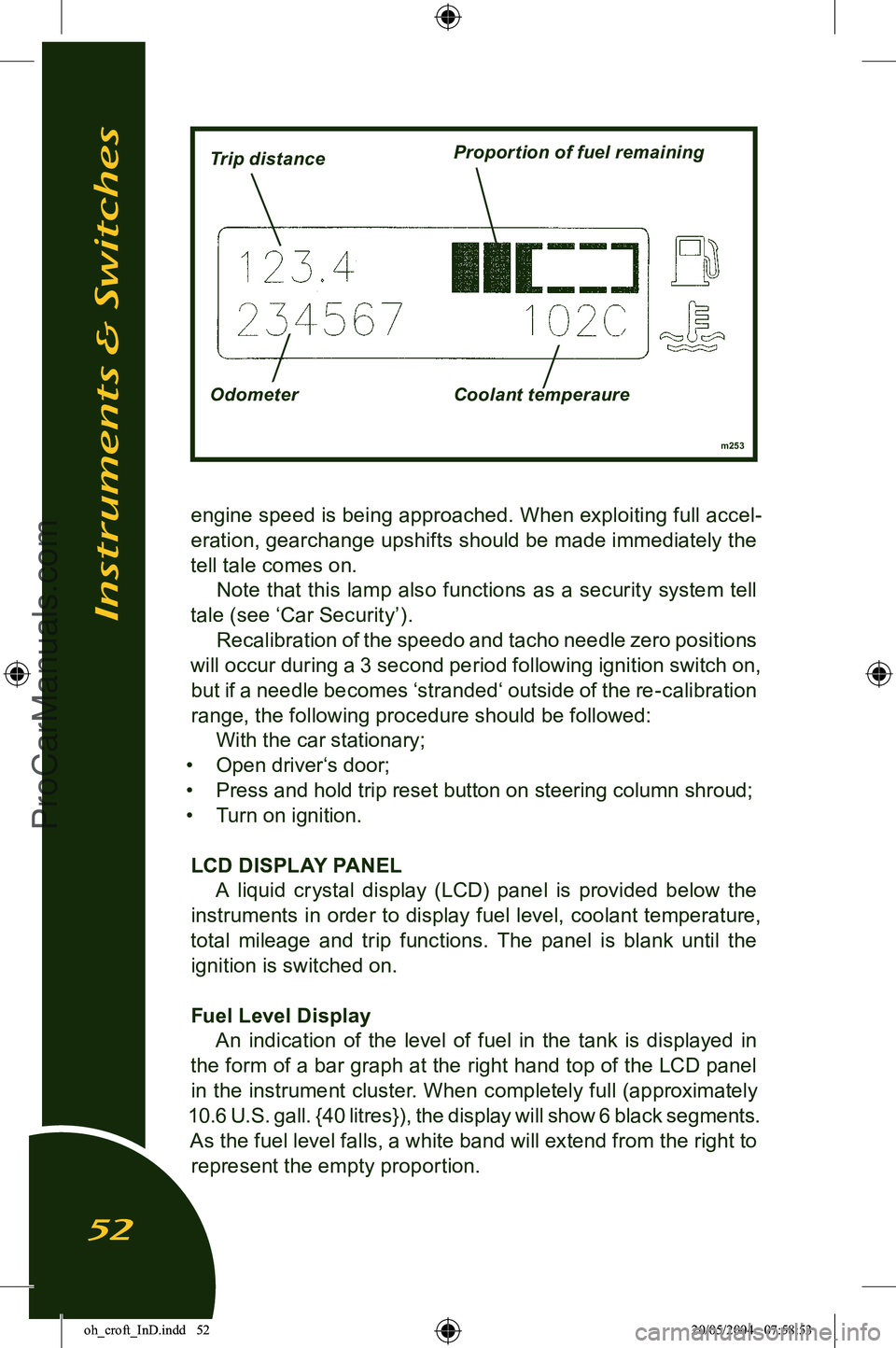
LCD DISPLAY PANEL A liquid crystal display (LCD) panel is provided below the
instruments in order to display fuel level, coolant temperature,
total mileage and trip functions. The panel is blank until the ignition is switched on.
Fuel Level Display An indication of the level of fuel in the tank is displayed in
the form of a bar graph at the right hand top of the LCD panel in the instrument cluster. When completely full (approximately
10.6 U.S. gall. {40 litres}), the display will show 6 black segments. As the fuel level falls, a white band will extend from the right to represent the empty proportion.
Instruments & Switches
52
m253
Trip distanceProportion of fuel remaining
Odometer Coolant temperaure
oh_croft_InD.indd 5220/05/2004 07:58:53ProCarManuals.com
Page 55 of 205
When only a single segment remains, representing approxi-
mately 1.3 U.S. gall. (5 litres), the amber low fuel tell tale will
ļ¬ash. Refuel at the next opportunity.
NOTICE: Do not allow the tank to run completely dry, as this may damage the catalytic converter and fuel pump. This may
affect the terms of your warranty.
Coolant Temperature Display The engine coolant temperature will be displayed at the bot
-
tom right hand corner of the panel as soon as the temperature reaches 162Ā°F. The running temperature will ļ¬uctuate a cer
-
tain amount as the operating conditions change, and during periods of idling or in heavy trafļ¬c, the temperature may rise to
over 212Ā°F, with the cooling fans switching on at half speed at
approximately 208Ā°F and at full speed at approximately 217Ā°F.
The temperature display will ļ¬ash at temperatures over 226Ā°F to prompt closer monitoring by the driver of high temperatures.
The pressurised cooling system has a boiling point of over 248Ā°F.
If the temperature approaches this level then the driver should be concerned. If this should occur, allow the engine to idle for a
few minutes whilst monitoring the temperature, and if it continues to rise, switch off and seek qualiļ¬ed assistance.
NOTICE: After a heavy snowfall, ensure that the radiator cooling
outlet grilles in the front body are cleared of snow before driving
the car, or overheating may occur.
Odometer An odometer (total distance recorder) reading is displayed at
the bottom left hand corner of the panel.
Trip Recorder A trip distance recorder is provided at the top left hand corner
of the panel. In order to zero the trip display, switch on the ignition, and
press for a moment (less than 1 second), the small button
on the steering column shroud ahead of the ignition switch.
This dual function button also controls the panel illumination
- see āInstrument & Switch Illuminationā.
Instruments & Switches
53
oh_croft_InD.indd 5320/05/2004 07:58:53ProCarManuals.com
Page 60 of 205
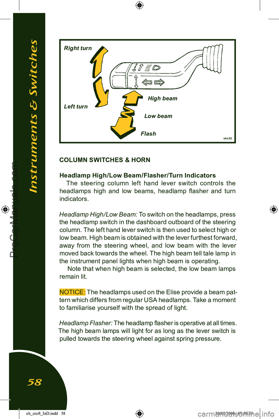
COLUMN SWITCHES & HORNHeadlamp High /Low Beam /Flasher/Turn Indicators The steering column lef t hand lever switch controls the
headlamps high and low beams, headlamp ļ¬asher and turn
indicators.
Headlamp High/Low Beam:
To switch on the headlamps, press
the headlamp switch in the dashboard outboard of the steering column. The left hand lever switch is then used to select high or
low beam. High beam is obtained with the lever furthest forward,
away from the steering wheel, and low beam with the lever moved back towards the wheel. The high beam tell tale lamp in
the instrument panel lights when high beam is operating.
Note that when high beam is selected, the low beam lamps
remain lit.
NOTICE:
The headlamps used on the Elise provide a beam pat-
tern which differs from regular USA headlamps. Take a moment
to familiarise yourself with the spread of light.
Headlamp Flasher:
The headlamp ļ¬asher is operative at all times.
The high beam lamps will light for as long as the lever switch is pulled towards the steering wheel against spring pressure.
Instruments & Switches
58
ohs32Flash
Right turn
Left turn
High beam
Low beam
oh_croft_InD.indd 5820/05/2004 07:58:55ProCarManuals.com
Page 62 of 205
Windscreen Washer: Two windscreen washer jets are provided,
one each side of the wiper spindle. Pulling the control lever to
-
wards the steering wheel will operate both the washer pump and the wiper. When the switch is released, the wiper will continue
for a further four sweeps.
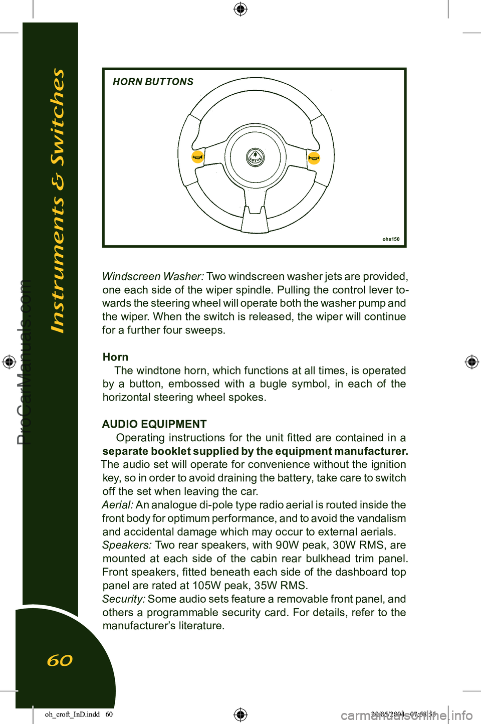
Horn The windtone horn, which functions at all times, is operated
by a button, embossed with a bugle symbol, in each of the
horizontal steering wheel spokes.
AUDIO EQUIPMENT Operating instructions for the unit ļ¬tted are contained in a
separate booklet supplied by the equipment manufacturer.
The audio set will operate for convenience without the ignition key, so in order to avoid draining the battery, take care to switch
off the set when leaving the car.
Aerial:
An analogue di-pole type radio aerial is routed inside the
front body for optimum performance, and to avoid the vandalism and accidental damage which may occur to external aerials.
Speakers:
Two rear speakers, with 90W peak, 30W RMS, are
mounted at each side of the cabin rear bulkhead trim panel.
Front speakers, ļ¬tted beneath each side of the dashboard top
panel are rated at 105W peak, 35W RMS.
Security:
Some audio sets feature a removable front panel, and
others a programmable security card. For details, refer to the
manufacturerās literature.
Instruments & Switches
60
ohs150
HORN BUTTONS
oh_croft_InD.indd 6020/05/2004 07:58:55ProCarManuals.com
Page 70 of 205
stopping distance, a locked wheel provides little or no steering
force, such that with both front wheels locked, movement of the steering wheel has no effect on car direction. With the anti-lock
system, even panic braking results in controlled deceleration and the retention of steering response. ABS is especially ad
-
vantageous when braking on slippery road surfaces and in bad driving conditions, but it is important to realise that the ABS
cannot increase the friction level at the road surface, but can only make optimum use of the grip available.
WARNING: When driving in adverse weather, or on poor road sur
-
faces, always be alert to the possibility of slippery condi
-
tions and make the necessary allowance for increased stop
-
ping distances. Failure to do so may result in an accident in which you or others may be killed or seriously injured.
Normal braking, controlled by the pressure applied to the
brake pedal, occurs when the road conditions allow for decel
-
eration to be achieved without danger of wheel lock. The relative
speeds of the four wheels are continuously monitored by the
ABS when the brakes are applied, and if one or more wheels begin to lock, the brake pressure to that wheel(s) is modulated
by the ABS to help keep the wheel rotating and provide the
maximum controlled braking force. The wheels may appear
to lock momentarily as the wheel speed rapidly changes, and some tire noise (intermittent screeching) may be heard which is normal and will vary with road and tire conditions. Note that the
ABS does not function at speeds below 5 mph (7 km/h). When the ABS is activated, the driver is will feel a āpulsingā
sensation at the brake pedal as the ļ¬uid pressure is modulated, and also by audible clicking sounds. These signals indicate to
the driver that maximum braking is occuring, and that driving style should be modiļ¬ed to suit the conditions.
The minimum stopping distance is achieved by applying the
brakes ļ¬rmly and steadily, and allowing the ABS to modulate
hydraulic pressure. The driver should not attempt to emulate
this process by āpumpingā the brake pedal, as modulation at the pedal will treat all four wheels similarly, rather than the individual
wheel control allowed by the electronics. An ABS tell tale lamp in the instrument panel is provided
to warn of any problems in the system and to indicate that the
Driving Controls
68
oh_croft_InD.indd 6820/05/2004 07:58:57ProCarManuals.com
Page 71 of 205
integral self diagnostics have switched out the anti-lock function.
See āABS tell tale lampā.
WARNING:
ā¢ The increased control that ABS provides should not induce you to take more risks with your safety. ABS will
not prevent a skid caused by abrupt steering movements,
or attempting to corner too quickly.
ā¢ Always maintain a safe following distance from other cars relative to the road surface and weather conditions.
Obey all trafļ¬c laws.
ā¢ Risk of accidents due to inappropriate speed cannot be reduced even by ABS. The driver is responsible for the
judgement of safe speed.
ā¢ The control unit of the ABS is set for standard tire size. If non-standard Tires are ļ¬tted, the control unit may mis-
interpret the speed of the car, because of the variant data
it receives from the wheel speed sensors. Fitting non standard tires would seriously affect the performance of
your ABS.
ā¢ The amber ABS tell tale in the instrument panel should light for about 4 seconds following ignition switch on, and
then go out. If the lamp remains lit, or comes on whilst driving, a fault in the anti-lock brake system is indicated.
The base brake system will continue to operate normally,
but without ABS. The car can be driven but should be
checked and repaired at the earliest opportunity.
ā¢ Activation of the ABS will vary according to the level of grip available at the Tires. On dry surfaces, activation
will occur only with a high pedal pressure. On slippery
surfaces, only a low pressure will be needed.
ā¢ On loose or uneven surfaces, such as gravel or snow, a car with ABS may need a longer stopping distance. Allow
a greater distance between cars in these conditions.
Driving Controls
69
oh_croft_InD.indd 6920/05/2004 07:58:57ProCarManuals.com