power LOTUS ELISE 2005 Owners Manual
[x] Cancel search | Manufacturer: LOTUS, Model Year: 2005, Model line: ELISE, Model: LOTUS ELISE 2005Pages: 205, PDF Size: 4.51 MB
Page 4 of 205
8. INSTRUMENTS & SWITCHES
Ignition Switch/Steering Lock ..........................................
44
Engine Start Button .........................................................
45
Warning âTell Taleâ Lamps ...............................................
46
Bulb Check ................................................................
46
Turn Tell Tale .............................................................
46
Seat Belt Tell Tale ......................................................
47
Brake Tell Tale ...........................................................
47
Oil Pressure Tell Tale ................................................
47
Low Fuel Level Tell Tale ............................................
48
ABS Tell Tale ............................................................
48
High Beam Tell Tale ..................................................
48
Airbag Tell Tale ..........................................................
48
Battery Charging Tell Tale .........................................
48
Engine Malfunction Indicator Lamp ...........................
49
Security/RPM Tell Tale ..............................................
49
Instruments .................................................................
51
Speedometer .............................................................
51
Tachometer ...............................................................
51
LCD Display Panel ....................................................
52
Fuel Level Display ...............................................
52
Coolant Temperature Display ..............................
53
Odometer ............................................................
53
Trip Recorder .......................................................
53
Dashboard Switches .......................................................
54
Parking Lamp Switch ................................................
54
Headlamp Switch ......................................................
54
Lights-on Buzzer .......................................................
55
Hazard Warning Lamps Switch .................................
55
Instrument Illumination ..............................................
56
Auxiliary Power Socket .............................................
57
Column Switches & Horn ................................................
58
Headlamp High/Low Beam/Flasher/Turn Indicators .
58
Windscreen Wiper/Washer .......................................
59
Horn .................................................................
60
Audio Equipment ............................................................
60
9. HEATING, VENTILATION & AIR CONDITIONING
Air Conditioning ..............................................................
61
Air Re-circulation ............................................................
62
Heater Temperature ........................................................
62
Fan Speed .................................................................
62
Air Distribution ................................................................
63
Engine Bay Ventilation ....................................................
65
Contents
2
oh_croft_InD.indd 220/05/2004 07:58:39ProCarManuals.com
Page 11 of 205
⢠Powerful anti-lock four wheel disc brakes.
⢠High geared responsive steering requiring only small steering
wheel movements to alter course
⢠Exceptional road holding with optimised handling character
-
istics
You and your passenger cannot take full advantage of these
safety features unless you remain sitting in a proper position
and always wear your seat belt properly. In fact, some safety
features can contribute to injuries if they are not used properly. Drivers should be aware of their own limitations as well as
those of the car, and ensure that all road driving is conducted
well within both sets of capabilities, particularly on wet roads, or under adverse weather conditions.
Remember:
Driving a car requires:
⢠Care;
⢠Attention; and
⢠Sensible judgement.
Be aware that any motor car has the potential to cause death
or injury both to its occupants and/or other persons, and must
be used only in a responsible and cautious manner. This entire
handbook is ï¬lled with important safety information.
Please
read it carefully.
Remember:
⢠ALWAYS WEAR YOUR SEAT BELT.
⢠Never drive while under the inï¬uence of alcohol or drugs.
⢠Never drive when excessively tired.
⢠Never use mobile phones, map read or attempt other distract
-
ing activities whilst driving.
⢠Always obey all speed and trafï¬c laws and regulations and never drive faster than the posted speed limit or than condi
-
tions allow.
⢠Be particularly careful driving on slippery or wet surfaces.
⢠Familiarise yourself with the car and always drive prudently, being aware of your own limitations and the limitations of the
car. Failure to operate the car properly can result in an ac
-
cident and serious injury.
Safety Information
9
oh_croft_InD.indd 920/05/2004 07:58:41ProCarManuals.com
Page 32 of 205
Car Security AlarmThe Lotus Elise is ï¬tted with a Cobra 8186 immobiliser/alarm
which includes the following features:
⢠âDynamic codingâ of the transmitter fobs; Each time the trans
-
mitters are used, the operating frequency is random changed
to guard against unauthorised code copying.
⢠Automatic (passive) engine immobilisation to prevent the engine from being started without the transmitter fob.
⢠Sensing switches on doors, front body access panels and the engine cover, meaning the alarm sounds if someone tries to
force entry.
⢠Personal protection by âon demandâ activation of the siren.
⢠Selectable cockpit intrusion sensing using a microwave
sensor.
⢠Self powered siren to maintain protection if the car battery is
disconnected.
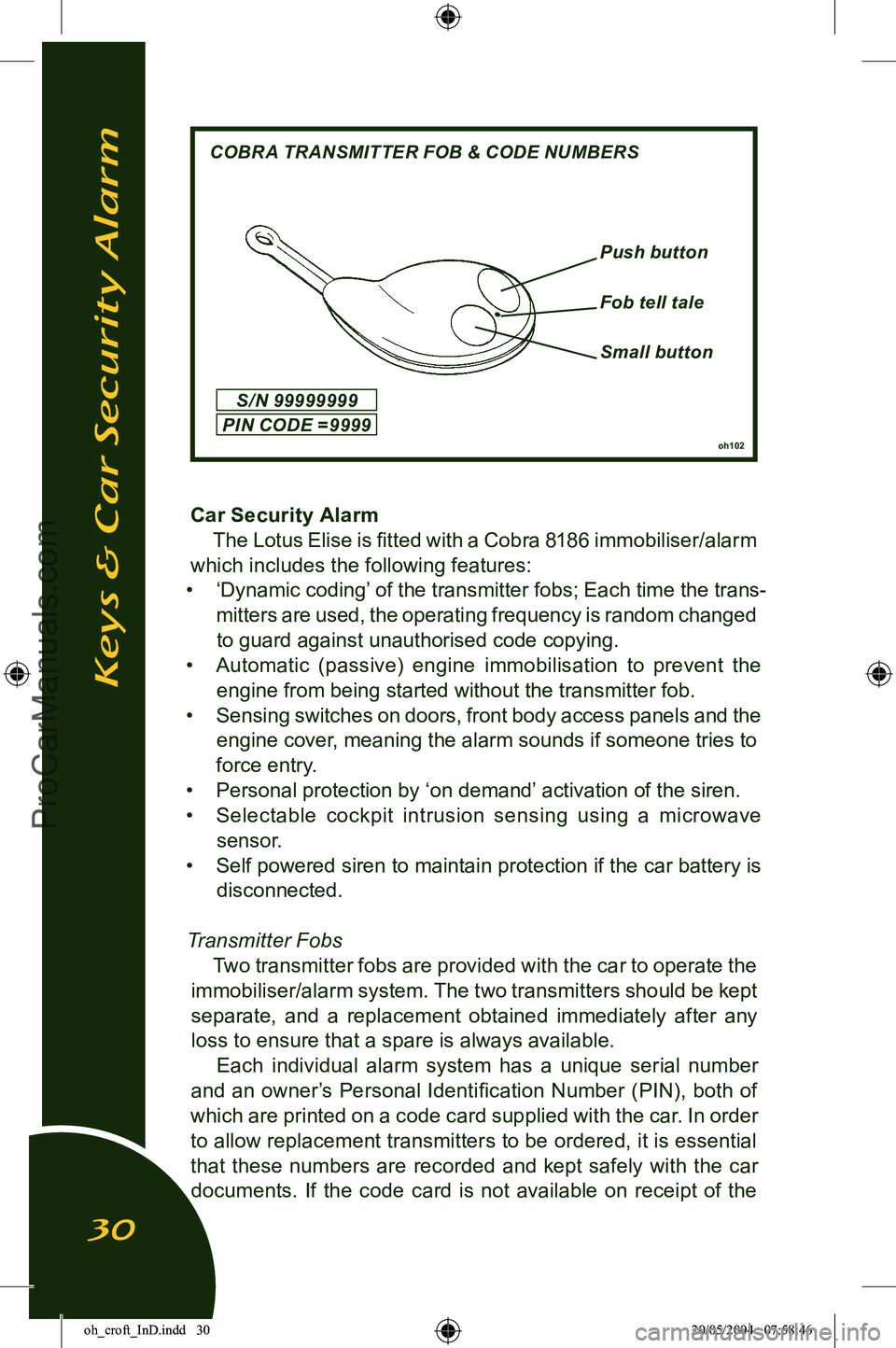
Transmitter Fobs Two transmitter fobs are provided with the car to operate the
immobiliser/alarm system. The two transmitters should be kept
separate, and a replacement obtained immediately after any loss to ensure that a spare is always available.
Each individual alarm system has a unique serial number
and an ownerâs Personal Identiï¬cation Number (PIN), both of
which are printed on a code card supplied with the car. In order to allow replacement transmitters to be ordered, it is essential
that these numbers are recorded and kept safely with the car
documents. If the code card is not available on receipt of the
oh102
Small button
Keys & Car Security Alarm
30
COBRA TRANSMITTER FOB & CODE NUMBERS
Push button
Fob tell tale
S / N 99999999
PIN CODE = 9999
oh_croft_InD.indd 3020/05/2004 07:58:46ProCarManuals.com
Page 34 of 205
Arming the AlarmRemove the ignition key, close (and lock) both doors, and
check that the engine cover and front body access panels are
secure. The roof may be either closed or open. Press once, and for a full second, the larger of the two buttons on the trans
-
mitter fob (on cars with central door locking, this action will automatically lock both doors - see later). This command will
be acknowledged by:
- 2 ï¬ashes of the hazard warning lamps;
- Continuous ï¬ashing of the security tell tale.
Check that these indications occur. If not, press the button a
second time, as the ï¬rst press may have only switched off the passive immobilisation (see above). Note that if the system is armed when a door or engine cover/
front access panel is not fully closed or if the interior lamp is in the âoffâ position, a continuous buzz will be heard as warning. If still open after expiry of the arming period, (see below)
the alarm will be armed with that switch group (both doors, or
front/rear access lids) excluded from the circuit.
After arming the system, the engine is immediately immo
-
bilised, but a period of approximately 45 seconds must elapse
before all functions and sensors become fully active. After
this time, the alarm will be triggered by any of the following actions:
- Interruption of the car battery power supply.
- Energising the ignition circuit (âhot wiringâ).
- Opening a door;
- Opening the engine cover or a front access panel.
- Movement detected within the cabin.
When the alarm is triggered, the hazard warning lamps will
ï¬ash and the electronic wailing siren will sound for a period of approximately 30 seconds before closing down and resetting, ready for any further triggering input. If a trigger is continuously
present, the alarm will repeat after a short delay, and continue
in this sequence for about 10 cycles. To silence the siren when triggered, press once, and for a full
second, the larger button on the transmitter fob. This will not affect the status of the alarm which will remain armed.
Keys & Car Security Alarm
32
oh_croft_InD.indd 3220/05/2004 07:58:47ProCarManuals.com
Page 37 of 205
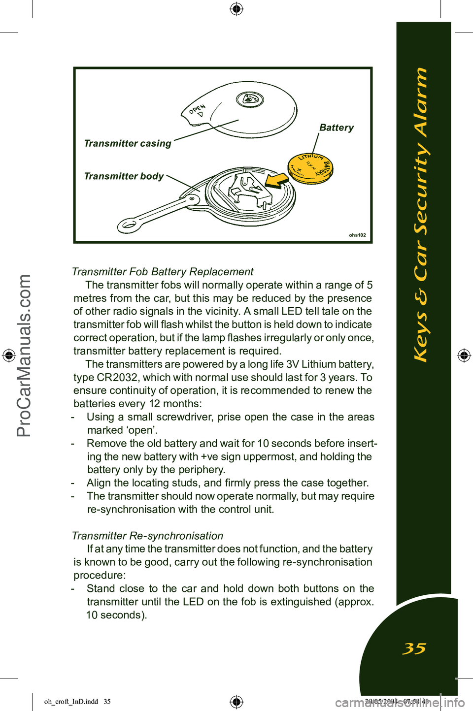
Transmitter Fob Battery ReplacementThe transmitter fobs will normally operate within a range of 5
metres from the car, but this may be reduced by the presence
of other radio signals in the vicinity. A small LED tell tale on the
transmitter fob will ï¬ash whilst the button is held down to indicate correct operation, but if the lamp ï¬ashes irregularly or only once,
transmitter battery replacement is required.
The transmitters are powered by a long life 3V Lithium battery,
type CR2032, which with normal use should last for 3 years. To ensure continuity of operation, it is recommended to renew the batteries every 12 months:
- Using a small screwdriver, prise open the case in the areas
marked âopenâ.
- Remove the old battery and wait for 10 seconds before insert
-
ing the new battery with +ve sign uppermost, and holding the battery only by the periphery.
- Align the locating studs, and ï¬rmly press the case together.
- The transmitter should now operate normally, but may require
re-synchronisation with the control unit.
Transmitter Re-synchronisation If at any time the transmitter does not function, and the battery
is known to be good, carry out the following re-synchronisation procedure:
- Stand close to the car and hold down both buttons on the
transmitter until the LED on the fob is extinguished (approx.
10 seconds).
ohs102
Keys & Car Security Alarm
35
Transmitter casing
Transmitter body
Batter y
oh_croft_InD.indd 3520/05/2004 07:58:48ProCarManuals.com
Page 41 of 205
Notes:
⢠In the event of a ï¬at car battery, the CDL will not operate. The
doors can be unlocked from outside only after opening the
engine cover and restoring power to the battery by substitution,
re-charging or âjumpingâ to a second battery. The doors cannot
be unlocked using the mechanical key if the CDL was used
to lock the car.
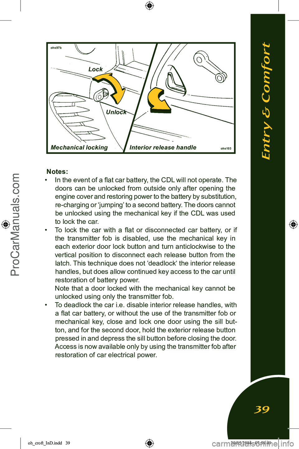
⢠To lock the car with a ï¬at or disconnected car battery, or if
the transmitter fob is disabled, use the mechanical key in each exterior door lock button and turn anticlockwise to the
vertical position to disconnect each release button from the latch. This technique does not âdeadlockâ the interior release
handles, but does allow continued key access to the car until restoration of battery power.
Note that a door locked with the mechanical key cannot be
unlocked using only the transmitter fob.
⢠To deadlock the car i.e. disable interior release handles, with
a ï¬at car battery, or without the use of the transmitter fob or mechanical key, close and lock one door using the sill but
-
ton, and for the second door, hold the exterior release button pressed in and depress the sill button before closing the door.
Access is now available only by using the transmitter fob after restoration of car electrical power.
ohs97b
ohs103
Mechanical locking Interior release handle
Entry & Comfort
39
LockUnlock
oh_croft_InD.indd 3920/05/2004 07:58:49ProCarManuals.com
Page 59 of 205
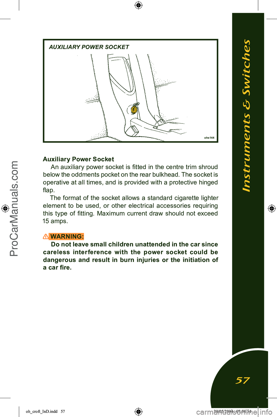
Auxiliary Power SocketAn auxiliary power socket is ï¬tted in the centre trim shroud
below the oddments pocket on the rear bulkhead. The socket is
operative at all times, and is provided with a protective hinged
ï¬ap. The format of the socket allows a standard cigarette lighter
element to be used, or other electrical accessories requiring
this type of ï¬tting. Maximum current draw should not exceed
15 amps.
WARNING: Do not leave small children unattended in the car since
careless inter ference with the power socket could be
dangerous and result in burn injuries or the initiation of a car ï¬re.
Instruments & Switches
57
ohs144
AUXILIARY POWER SOCKET
oh_croft_InD.indd 5720/05/2004 07:58:54ProCarManuals.com
Page 73 of 205
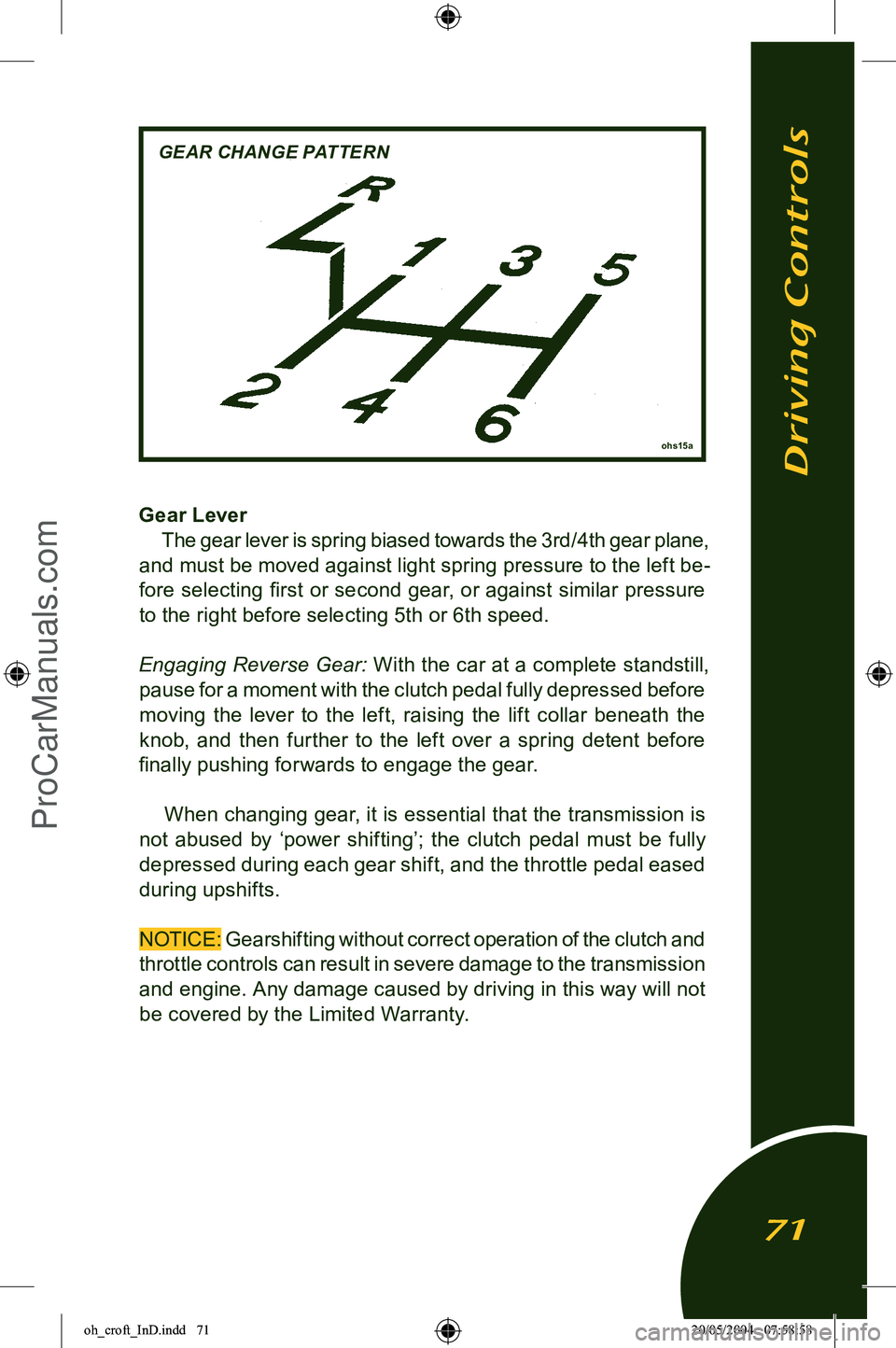
Gear LeverThe gear lever is spring biased towards the 3rd/4th gear plane,
and must be moved against light spring pressure to the left be
-
fore selecting ï¬rst or second gear, or against similar pressure to the right before selecting 5th or 6th speed.
Engaging Reverse Gear: With the car at a complete standstill
,
pause for a moment with the clutch pedal fully depressed before
moving the lever to the left, raising the lift collar beneath the
knob, and then further to the left over a spring detent before
ï¬nally pushing forwards to engage the gear.
When changing gear, it is essential that the transmission is
not abused by âpower shiftingâ; the clutch pedal must be fully
depressed during each gear shift, and the throttle pedal eased
during upshifts.
NOTICE: Gearshifting without correct operation of the clutch and
throttle controls can result in severe damage to the transmission
and engine. Any damage caused by driving in this way will not be covered by the Limited Warranty.
Driving Controls
71
ohs15a
GEAR CHANGE PATTERN
oh_croft_InD.indd 7120/05/2004 07:58:58ProCarManuals.com
Page 75 of 205
NOTICE: The use of wide throttle openings and/or high rpm before the engine has reached normal running temperature will
result in premature wear, and should be avoided.
Idle Speed Engine idle speed is controlled electronically by the engine
management computer, and is normally about 850 rpm. A
raised idle speed is required under certain operating conditions
including the engine warm up phase, when the increased speed helps the catalytic converter to reach operating temperature, as
well as inhibiting engine stall. Idle speed will return to normal automatically when the engine has warmed sufï¬ciently.
Engine Break-In Although the Elise powertrain is built to close tolerances
using modern technology, the progressive and sympathetic
breaking-in (or bedding-in) of a new engine and transmission
remains a major factor in attaining ef ï¬cient operation with
smooth, durable and economic performance to last throughout
the life of the car.
NOTICE: Failure to comply with the following break-in provi
-
sions could invalidate the terms of the car warranty:
It is important during the carâs early life to limit the workload on
the engine and thus control the heat generated within it, which is primarily a function of throttle opening and rpm. However, being
too sympathetic on the car will not allow the piston rings to bed in
satisfactorily, so a balance of spirited and gentle use is required.
For the ï¬rst 600 miles (1,000 km), use no more than moderate
throttle openings (about half of the available accelerator pedal
travel) and do not run the engine continuously at engine speeds over 4,500 rpm. Occasional short bursts at wider throttle and
higher rpm will be beneï¬cial, as will a constantly changing cruis
-
ing speed and making full use of the gearbox. Do not allow the
engine to labour in too high a gear ratio, but change down and
let the engine operate in its natural power band. When changing gear, use only a light touch on the gear lever.
Forcing the change will cause unnecessary wear on the system components and result in higher shift efforts being required. Al
-
low the brakes to bed-in by avoiding needless heavy braking for
the ï¬rst 100 miles (160 km). Both gearchange and brake pedal
Starting & Engine Break-In
73
oh_croft_InD.indd 7320/05/2004 07:58:59ProCarManuals.com
Page 76 of 205
efforts are likely to reduce during the break-in process.After 600 miles (1,000 km) have been covered, full throttle
and/or maximum rpm may be used for short periods, but not
until the ï¬rst âAfter Salesâ service has been carried out should
full car performance be exploited. Note that various operating parameters are continuously
monitored and recorded in the engine electronic controller. This
data may be downloaded by Lotus dealers on demand to assist
fault diagnosis and identify vehicle misuse.
Tires:
New tires also require a short âbreak-inâ period before
providing optimum grip.
Engine Special Features The engine of the Elise is designated V VTL-i for âVariable
Valve Timing and Lift - intelligentâ. Using microprocessor control, the inlet camshaft timing is advanced or retarded according to
immediate operating conditions, and the lift of both inlet and
exhaust valves is increased at high engine speed. This technol
-
ogy is used to provide high power output whilst retaining good
low speed response.
Starting & Engine Break-In
74
oh_croft_InD.indd 7420/05/2004 07:58:59ProCarManuals.com