battery LUCID AIR 2023 Owners Manual
[x] Cancel search | Manufacturer: LUCID, Model Year: 2023, Model line: AIR, Model: LUCID AIR 2023Pages: 241, PDF Size: 5.15 MB
Page 3 of 241
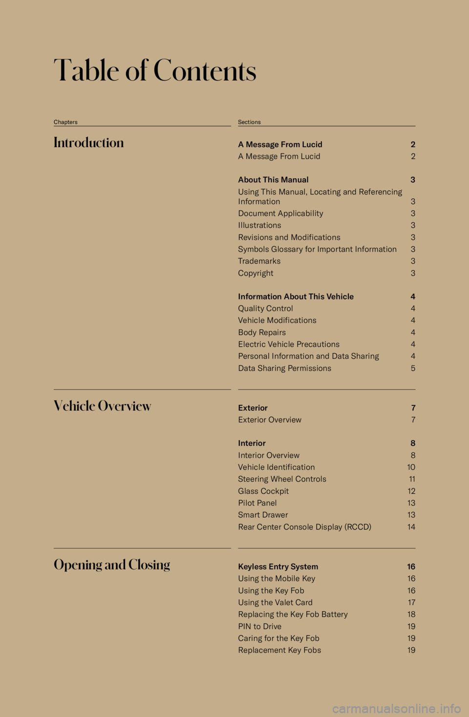
Table of Contents
ChaptersSectionsIntroductionA Message From Lucid 2
A Message From Lucid 2
About This Manual 3
Using This Manual, Locating and Referencing
Information 3
Document Applicability 3
Illustrations 3
Revisions and Modifications 3
Symbols Glossary for Important Information 3
Trademarks 3
Copyright 3
Information About This Vehicle 4
Quality Control 4
Vehicle Modifications 4
Body Repairs 4
Electric Vehicle Precautions 4
Personal Information and Data Sharing 4
Data Sharing Permissions 5Vehicle OverviewExterior 7
Exterior Overview 7
Interior 8Interior Overview 8
Vehicle Identification 10
Steering Wheel Controls 11
Glass Cockpit 12
Pilot Panel 13
Smart Drawer 13
Rear Center Console Display (RCCD) 14Opening and ClosingKeyless Entry System 16
Using the Mobile Key 16 Using the Key Fob 16Using the Valet Card 17
Replacing the Key Fob Battery 18
PIN to Drive 19
Caring for the Key Fob 19
Replacement Key Fobs 19
Page 5 of 241

Using Seat Belts When Pregnant 39Seat Belt Pre-tensioners 39
Testing Seat Belts 40
Child Safety 41
Guidelines for Seating Children 41
Choosing a Child Safety Seat 41
Seating Larger Children 42
Installing Child Safety Seats 42
Installing LATCH or ISOFIX Child Seats 43 Installing Seat Belt Retained Child Seats 44
Attaching Upper Tether Straps 44
Child Safety Seat Warnings 45
Airbags 46 Location of Airbags and Airbag Sensors 46
Airbag Safety Information 47
Airbag Safety Labels 47
How the Airbags Work 47
Types of Airbags 48
Obstruction of Airbags 49
Front Passenger Seat Occupant Classification
System (OCS) 50
Effects of Airbag Inflation 53
Airbag SRS Warning Indicator 53
Airbag Service Information 53Driving & OperatingDriver Information 55
Vehicle Information and Alerts 55
Trip Information 55
Pilot Panel 56
Extending and Retracting the Pilot Panel 56
Center Cockpit Panel 57
Center Cockpit Panel - Overview 57
Warning Indicators 58
High-Voltage Drive System Failure 64
Charge and Power Meter 64
Battery State of Charge Indicator 64
Starting and Powering Off 65
Starting 65 Powering Off 65
Steering Wheel 66Adjusting the Steering Wheel Position 66
Steering Feel and Sensitivity 66
Steering Wheel - Right Controls 67
Steering Wheel - Left Controls 68
Page 9 of 241
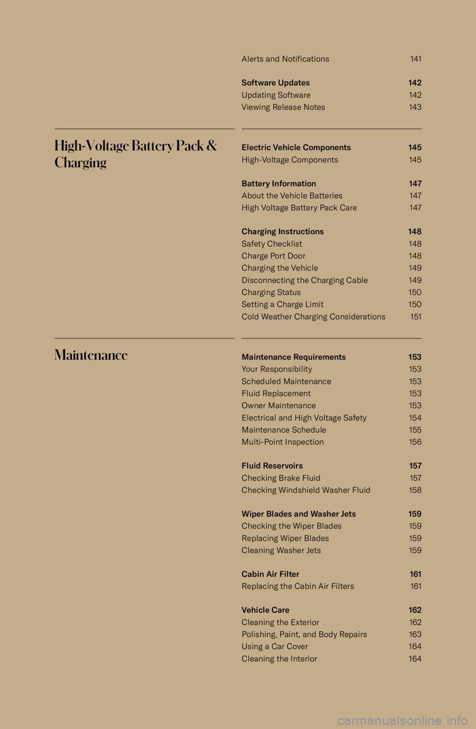
Alerts and Notifications 141
Software Updates 142
Updating Software 142 Viewing Release Notes 143High-Voltage Battery Pack &
ChargingElectric Vehicle Components 145
High-Voltage Components 145
Battery Information 147
About the Vehicle Batteries 147
High Voltage Battery Pack Care 147
Charging Instructions 148
Safety Checklist 148 Charge Port Door 148Charging the Vehicle 149Disconnecting the Charging Cable 149
Charging Status 150
Setting a Charge Limit 150
Cold Weather Charging Considerations 151MaintenanceMaintenance Requirements 153
Your Responsibility 153
Scheduled Maintenance 153
Fluid Replacement 153
Owner Maintenance 153
Electrical and High Voltage Safety 154
Maintenance Schedule 155
Multi-Point Inspection 156
Fluid Reservoirs 157
Checking Brake Fluid 157 Checking Windshield Washer Fluid 158
Wiper Blades and Washer Jets 159
Checking the Wiper Blades 159 Replacing Wiper Blades 159
Cleaning Washer Jets 159
Cabin Air Filter 161
Replacing the Cabin Air Filters 161
Vehicle Care 162
Cleaning the Exterior 162
Polishing, Paint, and Body Repairs 163
Using a Car Cover 164
Cleaning the Interior 164
Page 10 of 241
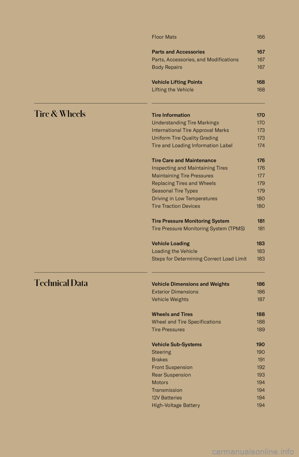
Floor Mats 166Parts and Accessories 167
Parts, Accessories, and Modifications167
Body Repairs 167
Vehicle Lifting Points 168
Lifting the Vehicle 168Tire & WheelsTire Information 170
Understanding Tire Markings 170 International Tire Approval Marks 173
Uniform Tire Quality Grading 173
Tire and Loading Information Label 174
Tire Care and Maintenance 176
Inspecting and Maintaining Tires 176
Maintaining Tire Pressures 177
Replacing Tires and Wheels 179
Seasonal Tire Types 179 Driving in Low Temperatures 180
Tire Traction Devices 180
Tire Pressure Monitoring System 181 Tire Pressure Monitoring System (TPMS) 181
Vehicle Loading 183
Loading the Vehicle 183
Steps for Determining Correct Load Limit 183Technical DataVehicle Dimensions and Weights 186
Exterior Dimensions 186
Vehicle Weights 187
Wheels and Tires 188
Wheel and Tire Specifications 188
Tire Pressures 189
Vehicle Sub-Systems 190
Steering 190
Brakes 191
Front Suspension 192
Rear Suspension 193
Motors 194
Transmission 194
12V Batteries 194
High-Voltage Battery 194
Page 11 of 241
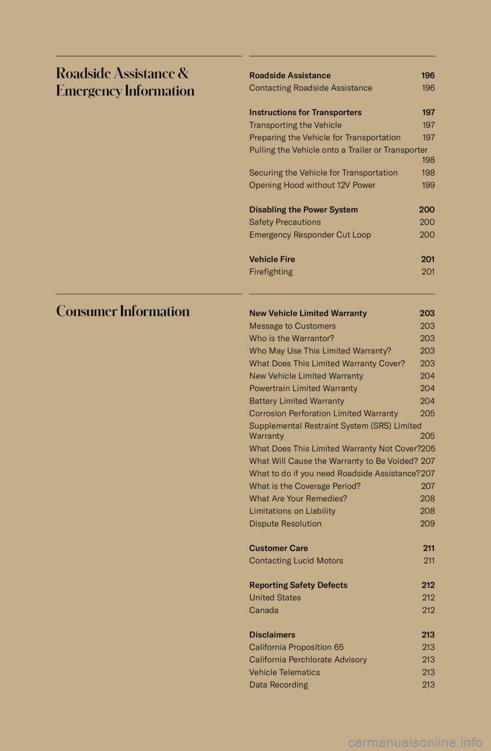
Roadside Assistance &Emergency InformationRoadside Assistance 196
Contacting Roadside Assistance 196
Instructions for Transporters 197
Transporting the Vehicle 197
Preparing the Vehicle for Transportation 197
Pulling the Vehicle onto a Trailer or Transporter 198
Securing the Vehicle for Transportation 198
Opening Hood without 12V Power 199
Disabling the Power System 200
Safety Precautions 200 Emergency Responder Cut Loop 200
Vehicle Fire 201
Firefighting 201Consumer InformationNew Vehicle Limited Warranty 203
Message to Customers 203 Who is the Warrantor? 203Who May Use This Limited Warranty? 203
What Does This Limited Warranty Cover? 203 New Vehicle Limited Warranty 204
Powertrain Limited Warranty 204
Battery Limited Warranty 204
Corrosion Perforation Limited Warranty 205
Supplemental Restraint System (SRS) Limited
Warranty 205
What Does This Limited Warranty Not Cover?205 What Will Cause the Warranty to Be Voided? 207
What to do if you need Roadside Assistance? 207
What is the Coverage Period? 207
What Are Your Remedies? 208 Limitations on Liability 208Dispute Resolution 209
Customer Care 211
Contacting Lucid Motors 211
Reporting Safety Defects 212
United States 212
Canada 212
Disclaimers 213
California Proposition 65 213 California Perchlorate Advisory 213
Vehicle Telematics 213
Data Recording 213
Page 12 of 241

Vehicle Recycling 215
High-Voltage Battery Recycling Process 215
FCC, FDA, and ISED Compliance 216
FCC and ISED Certification 216
Page 70 of 241
Center Cockpit Panel
Center Cockpit Panel - Overview
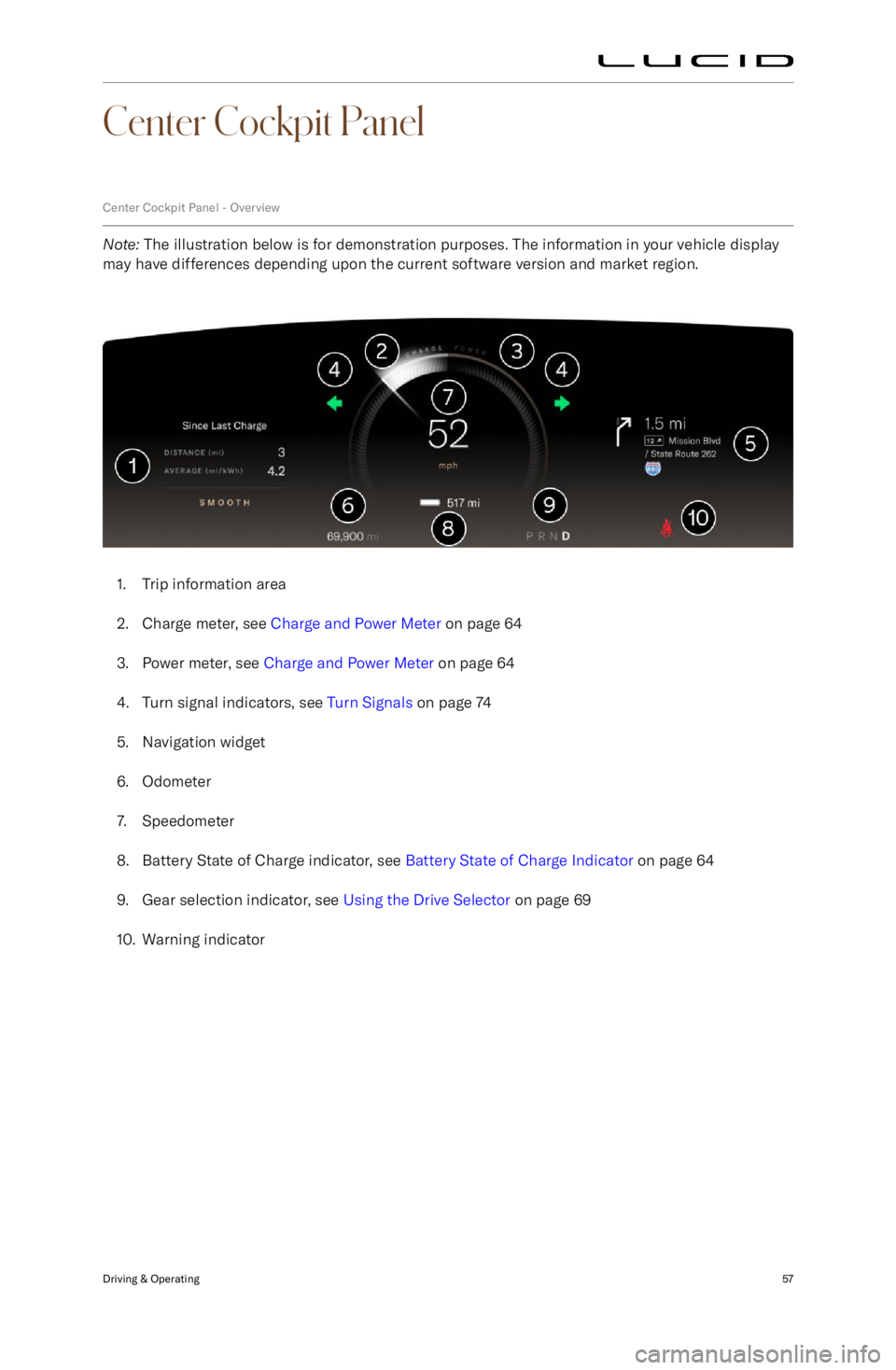
Note: The illustration below is for demonstration purposes. The information in your vehicle display
may have differences depending upon the current software version and market region.
1. Trip information area
2. Charge meter, see Charge and Power Meter on page 64
3. Power meter, see Charge and Power Meter on page 64
4. Turn signal indicators, see Turn Signals on page 74
5. Navigation widget
6. Odometer
7. Speedometer
8. Battery State of Charge indicator, see Battery State of Charge Indicator on page 64
9. Gear selection indicator, see Using the Drive Selector on page 69
10. Warning indicator
Driving & Operating57
Page 72 of 241
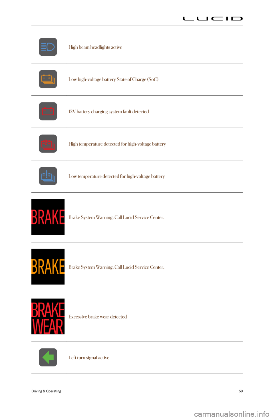
High beam headlights activeLow high-voltage battery State of Charge (SoC)12V battery charging system fault detectedHigh temperature detected for high-voltage batteryLow temperature detected for high-voltage battery
Brake System Warning. Call Lucid Service Center.Brake System Warning. Call Lucid Service Center.Excessive brake wear detected
Left turn signal active
Driving & Operating59
Page 77 of 241
High-Voltage Drive System Failure
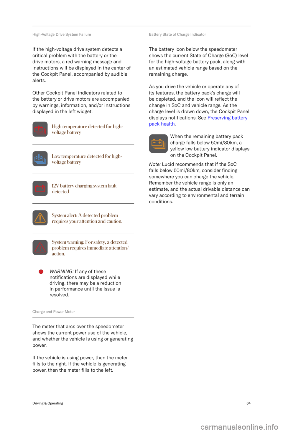
If the high-voltage drive system detects a
critical problem with the battery or the drive motors, a red warning message andinstructions will be displayed in the center of
the Cockpit Panel, accompanied by audible
alerts.
Other Cockpit Panel indicators related to
the battery or drive motors are accompanied
by warnings, information, and/or instructions
displayed in the left widget.High temperature detected for high-
voltage batteryLow temperature detected for high-
voltage battery12V battery charging system fault
detectedSystem alert: A detected problem
requires your attention and caution.System warning: For safety, a detected
problem requires immediate attention/
action.WARNING: If any of these
notifications are displayed while
driving, there may be a reduction
in performance until the issue is
resolved.
Charge and Power Meter
The meter that arcs over the speedometer
shows the current power use of the vehicle,
and whether the vehicle is using or generating
power.
If the vehicle is using power, then the meter
fills to the right. If the vehicle is generating
power, then the meter fills to the left.
Battery State of Charge Indicator
The battery icon below the speedometer
shows the current State of Charge (SoC) level
for the high-voltage battery pack, along with an estimated vehicle range based on the
remaining charge.
As you drive the vehicle or operate any of
its features, the battery pack
Page 83 of 241
Drive Modes
Using Neutral
1. To shift out of park unlock the car witheither the keyfob, the nfc card, a pairedphone, or the phone app with correct
credentials.
2. Once the car is unlocked and powered on, you can open the driver door and
shift to neutral by pressing the brake
pedal and operating the shift lever.
The park brake will disengage, and the
vehicle will be ready to be pushed or
pulled.
3. If the electrical system of the vehicle is dead where the vehicle does not
wake up and unlock when asked for, the operator needs to connect a 12v jump-
start battery to the jump-start terminal so that operations A and B can be
conducted.
Drive Modes
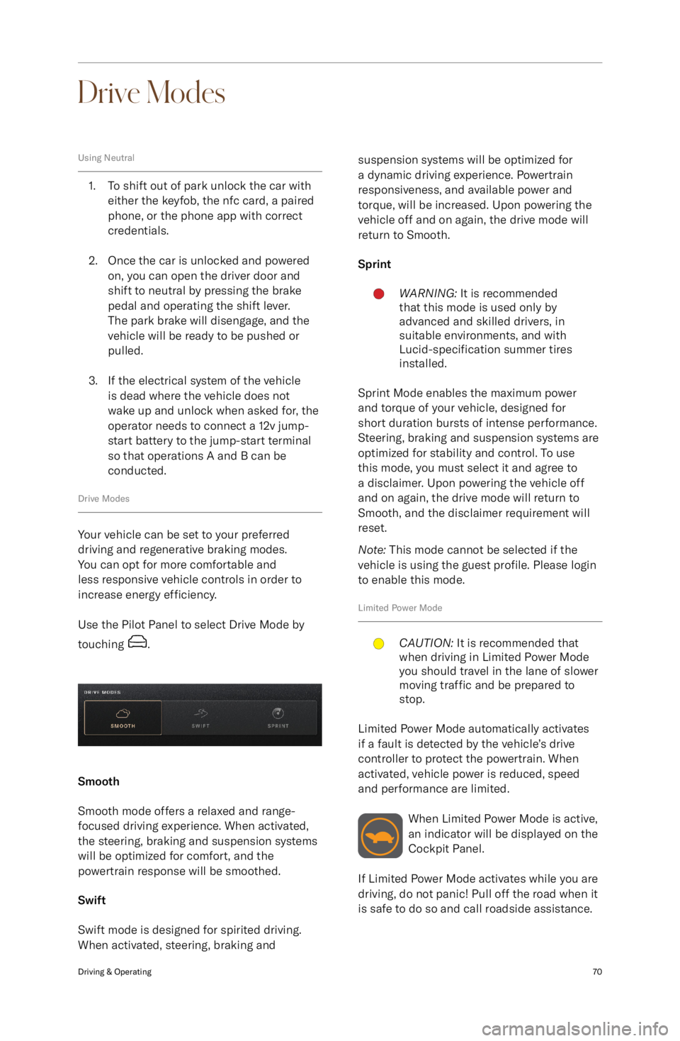
Your vehicle can be set to your preferred
driving and regenerative braking modes.
You can opt for more comfortable and
less responsive vehicle controls in order to increase energy efficiency.
Use the Pilot Panel to select Drive Mode by
touching
.
Smooth
Smooth mode offers a relaxed and range-
focused driving experience. When activated,
the steering, braking and suspension systems
will be optimized for comfort, and the
powertrain response will be smoothed.
Swift
Swift mode is designed for spirited driving.
When activated, steering, braking and
suspension systems will be optimized for
a dynamic driving experience. Powertrain
responsiveness, and available power and
torque, will be increased. Upon powering the
vehicle off and on again, the drive mode will return to Smooth.
SprintWARNING: It is recommended
that this mode is used only by
advanced and skilled drivers, in
suitable environments, and with
Lucid-specification summer tires
installed.
Sprint Mode enables the maximum power
and torque of your vehicle, designed for
short duration bursts of intense performance.
Steering, braking and suspension systems are
optimized for stability and control. To use
this mode, you must select it and agree to
a disclaimer. Upon powering the vehicle off
and on again, the drive mode will return to
Smooth, and the disclaimer requirement will
reset.
Note: This mode cannot be selected if the
vehicle is using the guest profile. Please login
to enable this mode.
Limited Power Mode
CAUTION: It is recommended that
when driving in Limited Power Mode
you should travel in the lane of slower
moving traffic and be prepared to
stop.
Limited Power Mode automatically activates
if a fault is detected by the vehicle