alarm MASERATI GHIBLI 2019 User Guide
[x] Cancel search | Manufacturer: MASERATI, Model Year: 2019, Model line: GHIBLI, Model: MASERATI GHIBLI 2019Pages: 384, PDF Size: 13.33 MB
Page 55 of 384
locked and the alarm system will not
be armed.
When the power trunk lid is
completely open if you press and
release the RH button
, the power
trunk lid will be completely closed
unless it is stopped;
• if instead the power trunk lid is in an
intermediate position and you press
and release the RH button
during
the closing or opening stroke, it will
be stopped;
• if instead the power trunk lid is
stopped in an intermediate position
and you press and release the RH
button
, it will reverse its previous
movement and it will be completely
opened or closed unless it is stopped
again.
In any case, when you press the RH
button
, the doors will not be
locked and the alarm system will not
be armed immediately, but only when
the power trunk lid will have reached
the totally closed position as effect of
every movement commands received
from every other available inputs.
NOTE:
• The order of the functions shown
does not represent the sequence in
which they can be performed. • The buttons of the Power Trunk
Lid/Hands Free do not work if a gear
is engaged or if the vehicle speed is
higher than 0 (km/h - mph).
• The Power Trunk Lid/Hands Free
does not work with temperatures
lower than −22°F (−30°C) or higher
than 150°F (65°C).
• If the opening buttons or the
handles are operated while the
Power Trunk Lid/Hands Free is
closing, the stroke of lid stops.
Pressing another time the same
command it reverses movement and
fully open.
• If the opening buttons or the handle
are operated while the Power Trunk
Lid/Hands Free is opening, the motor
of the lid is disabled to allow manual
operation.
• If the Power Trunk Lid/Hands Free
finds several obstacles during the
same operating cycle, it will stop
automatically and must be opened
or closed manually.
• If the Power Trunk Lid/Hands Free is
closing and a gear is engaged, the
lid will continue closing. In this
condition, it is possible that, during
the closing stroke, it may find an
obstacle and stop. Set the Position of Maximum Power
Trunk Lid Opening
The maximum opening position of the
trunk lid can be modified using the
previously described buttons on its
right lower side.
1. Activate the trunk lid and stop it in
the new maximum opening
position to be set, by pressing the
LH
button.
2. Press the LH
and RH buttons
at the same time and keep them
pressed for 3 seconds.
3. Release both buttons. Upon the
following opening controls, the
trunk lid will stop in the stored
position.
If you want to reset the maximum
possible opening position of the
power trunk lid, proceed as described
below starting from the previously set
opening position.
1. Manually push the trunk lid to the
maximum possible opening
position.
2. Repeat the previously performed
steps 2 and 3.
Power Trunk Lid/Hands Free
Automatic Safe Movement
Power Trunk Lid/Hands Free safe
opening and closing is ensured by aBefore Starting
2
51
Page 142 of 384
in OFF position. Opening either front
door will cancel this feature. The
ignition system timing can be set using
the MTC+ System (see “MTC+ Settings”
in section “Dashboard Instruments and
Controls”).
Sunroof Maintenance Use only a nonabrasive cleaner and a
soft cloth to clean the glass panel.
HomeLink ®
(optional) HomeLink ®
replaces up to three
hand-held transmitters operating the
automatic devices that open garage
doors and gates, enable/disable the
lighting or security systems. The
HomeLink ®
unit is powered by your
vehicle's 12 Volt battery. The
HomeLink ®
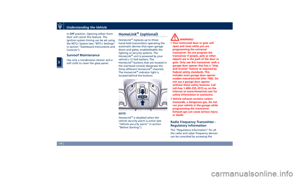
buttons that are located in
the overhead console designate the
three different HomeLink ®
channels.
The HomeLink ®
indicator light is
located behind the buttons.
NOTE:
HomeLink ®
is disabled when the
vehicle security alarm is active (see
“Vehicle security alarm” in section
“Before Starting”). WARNING!
• Your motorized door or gate will
open and close while you are
programming the universal
transceiver. Do not program the
transceiver if people, pets or other
objects are in the path of the door or
gate. Only use this transceiver with a
garage door opener that has a “stop
and reverse” feature as required by
Federal safety standards. This
includes most garage door opener
models manufactured after 1982. Do
not use a garage door opener
without these safety features. Call
toll-free 1–800–355–3515 or, on the
Internet at www.HomeLink.com for
safety information or assistance.
• Vehicle exhaust contains carbon
monoxide, a dangerous gas. Do not
run your vehicle in the garage while
programming the transceiver.
Exhaust gas can cause serious injury
or death.
Radio Frequency Transmitter -
Regulatory Information The “Regulatory Information” for all
the radio and radar frequency devices
can be consulted by accessing theUnderstanding the Vehicle
3
138
Page 145 of 384
• Press and hold the programmed
HomeLink ®
button.
If the garage door opener/device
activates, programming is complete.
To program the remaining two
HomeLink ®
buttons, repeat each step
for each remaining button. Do not
erase the channels.
Reprogramming a Single HomeLink ®
Button
To reprogram a channel that has been
previously trained, follow these steps:
• Place the ignition device to the RUN
position without starting the engine.
• Press and hold the desired
HomeLink ®
button.
• Without releasing the button
proceed with “Programming the
hand-held transmitters” from second
step and follow all remaining steps.
Using HomeLink ®
To operate, press and release the
programmed HomeLink ®
button.
Activation will now occur for the
programmed device (i.e., garage door
opener, gate operator, security system,
entry door lock, home/office lighting,
etc.). The hand-held transmitter of the
device may also be used at any time. Security It is advisable to erase all channels
before you sell or turn in your vehicle.
To erase the channels press and hold
the two outside HomeLink ®
buttons (I
and III) until the indicator light starts
flashing (after approximately 20
seconds).
The HomeLink ®
Universal Transceiver
is disabled when the vehicle security
alarm is active (see “Vehicle security
alarm” in section “Before Starting”).
Troubleshooting Tips If you are having trouble while
programming HomeLink ®
, here are
some of the most common solutions:
• Replace the battery in the original
hand-held transmitter.
• Press the LEARN button on the
garage door opener to complete the
training for a rolling code.
• Did you unplug the device for
programming and forgot to plug it
back in?
If you have any problems, or require
assistance, please call toll-free
1–800–355–3515 or, on the Internet at
www.HomeLink.com for information
or assistance. Understanding the Vehicle
3
141
Page 273 of 384

NOTE:
In a parking lot situation, oncoming
vehicles can be obscured by vehicles
parked on either side. If the sensors
are blocked by other structures or
vehicles, the system will not be able to
alert the driver.
Proceed slowly and cautiously out of
the parking space until the rear end of
the vehicle is moderately exposed.
The RCP system will then have a clear
view of the cross traffic. If an
oncoming vehicle is detected, the RCP
system will alert the driver using both
the visual and audible alarms. If the
radio is on, it will also reduce the
radio volume.
WARNING!
RCP is not a Back Up Aid system. More specifically, it is intended to be used
to help a driver detect an oncoming
vehicle in a parking lot situation.
Drivers must be careful when backing
up, even when using RCP. Always
check carefully behind your vehicle,
look behind you, and be sure to check
for pedestrians, animals, other
vehicles, obstructions, and blind spots
before backing up. Failure to do so
can result in serious injury or death.
BSA and RCP Setting Setting modes can be selected from
the MTC+ System.
Touch “Controls” soft-key and then
“Blind Spot Assist” soft-key to enter
the setting page.
Refer to chapter “MTC+ “Controls”
Screen” in section “Dashboard
Instruments and Controls” for further
information. BSA in Visual Mode
When operating in “Visual” mode, the
BSA system will provide a visual alert
in the appropriate side view mirror
when it detects a vehicle or an object
in the detection areas monitored by its
sensors: depending on the status of
the relative turn indicator, the
warning light can be fixed or flashing.
However, when the system is
operating in RCP mode, it will respond
with both visual and audible alerts
when an oncoming vehicle or an
object approaching the rear end side
of the vehicle is detected.
Whenever an audible alert is
requested, the radio is muted (if the
radio is on).
BSA in Visual and Acoustic Mode
When operating in “Visual & Acoustic”
mode, the BSA system will provide a
visual alert in the appropriate side
view mirror based on a detected
vehicle or object.Driving
5
269
Page 342 of 384
• on the fuse and relay box located in
a covered area, behind the glove
compartment on the dashboard left
side.
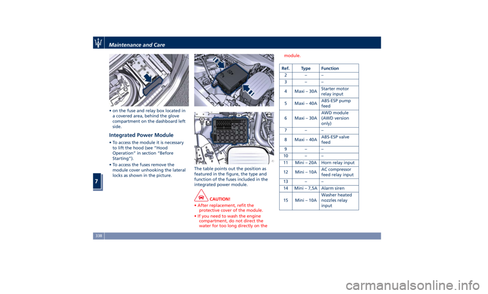
Integrated Power Module • To access the module it is necessary
to lift the hood (see “Hood
Operation” in section “Before
Starting”).
• To access the fuses remove the
module cover unhooking the lateral
locks as shown in the picture. The table points out the position as
featured in the figure, the type and
function of the fuses included in the
integrated power module.
CAUTION!
• After replacement, refit the
protective cover of the module.
• If you need to wash the engine
compartment, do not direct the
water for too long directly on the module.
Ref. Type Function
2––
3––
4 Maxi – 30A Starter motor
relay input
5 Maxi – 40A ABS-ESP pump
feed
6 Maxi – 30A AWD module
(AWD version
only)
7––
8 Maxi – 40A ABS-ESP valve
feed
9––
10 – –
11 Mini – 20A Horn relay input
12 Mini – 10A AC compressor
feed relay input
13 – –
14 Mini – 7,5A Alarm siren
15 Mini – 10A Washer heated
nozzles relay
inputMaintenance and Care
7
338
Page 360 of 384
• With the transmission in N (Neutral),
let the engine idle for several
minutes.
WARNING!
The engine idle must be performed
outdoors. Exhaust gases contain
carbon monoxide which is strongly
toxic and potentially lethal.
WARNING!
California Proposition 65
Operating, servicing and maintaining
a passenger vehicle or off-road vehicle
can expose you to chemicals including
such as, engine exhaust, carbon
monoxide, phthalates and lead, that
which are known to the State of
California to cause cancer and birth
defects or other reproductive harm. To
minimize exposure, avoid breathing
exhaust, do not idle the engine except
as necessary, service your vehicle in a
well-ventilated area and wear gloves
or wash your hands frequently when
servicing your vehicle. For more
information go to:
www.P65Warnings.ca.gov/passenger-
vehicle Battery Statement Battery Statement Status of
Charge To avoid problems with ignition and/or
the electrical system in general when
you are driving, the battery charge
status is constantly maintained and
guaranteed by the vehicle's recharge
circuit; the main component of which
is the alternator. This circuit is only
able to supply voltage to the battery
when the vehicle is traveling.
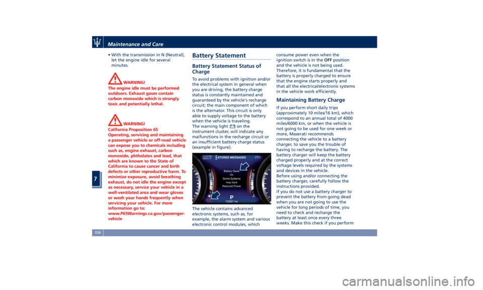
The warning light
on the
instrument cluster, will indicate any
malfunctions in the recharge circuit or
an insufficient battery charge status
(example in figure).
The vehicle contains advanced
electronic systems, such as, for
example, the alarm system and various
electronic control modules, which consume power even when the
ignition switch is in the OFF position
and the vehicle is not being used.
Therefore, it is fundamental that the
battery is properly charged to ensure
that the engine starts properly and
that all the electrical/electronic systems
in the vehicle work efficiently.
Maintaining Battery Charge If you perform short daily trips
(approximately 10 miles/16 km), which
correspond to an annual total of 4000
miles/6000 km, or when the vehicle is
not going to be used for one week or
more, Maserati recommends
connecting the vehicle to a battery
charger, to save you the trouble of
having to recharge the battery. The
battery charger will keep the battery
charged properly and at the correct
voltage levels required by the systems
and devices in the vehicle.
Before using and/or connecting the
battery charger, carefully follow the
instructions provided.
If you do not use a battery charger to
prevent the battery from going dead
when you are not going to use the
vehicle for long periods of time, you
need to check and recharge the
battery at least once every three
weeks. Make this check if you performMaintenance and Care
7
356
Page 376 of 384
Abbreviations .................8
Accessories
Aftermarket Parts and Accessories
Statement .................13
Active Blind Spot Assist - ABSA . . . .271
Adaptive Cruise Control (ACC) . . . .247
Activation/Deactivation ...... .250
Display Warnings and
Maintenance ............. .255
Precautions while Driving with
ACC ................... .256
Setting the Following Distance . .252
Setting the Speed .......... .251
Airbag.....................64
Advanced Front Air Bag
Properties .................65
Air Bag Deployment Result .....70
Air Bag Deployment Sensors and
Controls ..................15
Air Bag System Components .....64
Front Air Bag Inflator Units .....68
Passenger Air bag Labels .......20
Supplemental Driver Side Knee Air
bag......................67
Supplemental Restraint System
(SRS) .....................64
Supplemental Seat-mounted Side
Air Bags (SAB) ..............66
Supplemental Side Air Bag Inflatable
Curtain (SABIC) ..............67
Transport of persons with
disability ..................71
Air Conditioning (A/C) System . . . .197 A/C Distribution ........... .142
Alarm, Vehicle Security ..........27
ALR (Automatic Locking Retractor) . .61
Anti-Lock Braking System (ABS) and
Electronic Brake-force Distribution
(EBD) ................... .239
Assistance ...................11
Assistance, if you need ..........11
ATC (Automatic Temperature
Control) ................. .202
Audio Controls .............. .176
Audio Controls on Central
Console ................. .176
Steering Wheel Audio Controls . .176
Audio, setting .............. .191
Audio System ............... .177
Automatic Transmission
Manual Release of Transmission .315
AWD
All-Wheel Drive, drive mode . . . .223
BAS (Brake Assist System) ...... .240
Battery ................... .332
Battery Recharge .......... .335
Battery Remote Posts Position. . .313
Maintaining Battery Charge . . . .356
To Disconnect the Battery .... .332
To Reconnect the Battery ..... .334
Blind Spot Alert ............. .266
RCP - Rear Cross Path ........ .268
Bluetooth, Customer settings .... .192
Bodywork
Maintenance and
Care . .350
Pre-Short Drop Function ..... .353 Protection from Atmospheric
Agents ................. .350
Useful Advice to Keep the Bodywork
in Good Condition ......... .351
Brakes
Brake and Stability Control System
(ESC) ................... .238
Brake Overheating ......... .242
Brake System ............. .238
Manual Release of Parking
Brake .................. .311
Parking Brake ............. .233
Using the Brakes ........... .241
Capacity/Refillings ........... .360
Cargo Area ................ .133
Loading with Rear Seatbacks Folded
Down .................. .134
Vehicle Load Carrying Capacity . .133
Child Restraint Systems ..........72
Children too large for Booster
Seats .....................73
Infants and Child Restraints .....72
Installing Child Restraint Systems
using the Vehicle Seat Belt equipped
with ALR ..................74
Lower Anchors and Tether for
Children (LATCH) ............75
Older Children and Child
Restraints .................73
Tips on getting the most out of your
child restraint ...............74
Climate Control ............. .197Index
9 372