trunk release MASERATI GHIBLI 2019 User Guide
[x] Cancel search | Manufacturer: MASERATI, Model Year: 2019, Model line: GHIBLI, Model: MASERATI GHIBLI 2019Pages: 384, PDF Size: 13.33 MB
Page 58 of 384
Trunk Safety WARNING!
Do not allow children to have access
to the trunk. Always close the trunk
lid when your vehicle is unattended.
Once in the trunk, young children may
not be able to escape. If trapped in the
trunk, children can die from
suffocation or heat stroke.
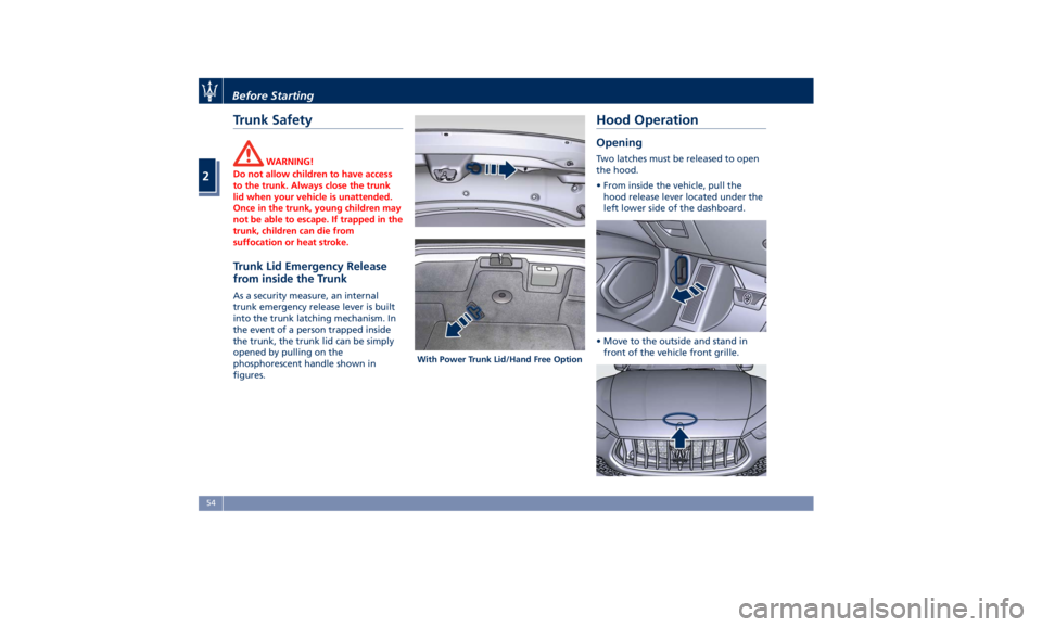
Trunk Lid Emergency Release
from inside the Trunk As a security measure, an internal
trunk emergency release lever is built
into the trunk latching mechanism. In
the event of a person trapped inside
the trunk, the trunk lid can be simply
opened by pulling on the
phosphorescent handle shown in
figures. Hood Operation Opening Two latches must be released to open
the hood.
• From inside the vehicle, pull the
hood release lever located under the
left lower side of the dashboard.
• Move to the outside and stand in
front of the vehicle front grille.With Power Trunk Lid/Hand Free OptionBefore Starting
2
54
Page 98 of 384
11 Rear power sunshade and rear
seats comfort controls panel (if
equipped).
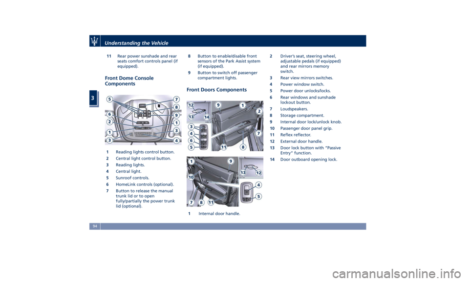
Front Dome Console
Components
1 Reading lights control button.
2 Central light control button.
3 Reading lights.
4 Central light.
5 Sunroof controls.
6 HomeLink controls (optional).
7 Button to release the manual
trunk lid or to open
fully/partially the power trunk
lid (optional). 8 Button to enable/disable front
sensors of the Park Assist system
(if equipped).
9 Button to switch off passenger
compartment lights.
Front Doors Components
1 Internal door handle. 2 Driver’s seat, steering wheel,
adjustable pedals (if equipped)
and rear mirrors memory
switch.
3 Rear view mirrors switches.
4 Power window switch.
5 Power door unlocks/locks.
6 Rear windows and sunshade
lockout button.
7 Loudspeakers.
8 Storage compartment.
9 Internal door lock/unlock knob.
10 Passenger door panel grip.
11 Reflex reflector.
12 External door handle.
13 Door lock button with “Passive
Entry” function.
14 Door outboard opening lock.Understanding the Vehicle
3
94
Page 113 of 384
the lever is shifted out of the reverse
position. Each memory set of the
driver's seat (see "Driver Memory
Seat" chapter in section
“Understanding the Vehicle”)
corresponds to a mirror tilt position in
reverse.
NOTE:
The mirrors tilt in reverse can be
turned on and off using the MTC+
System, refer to “MTC+ Settings” in
section “Dashboard Instruments and
Controls”.
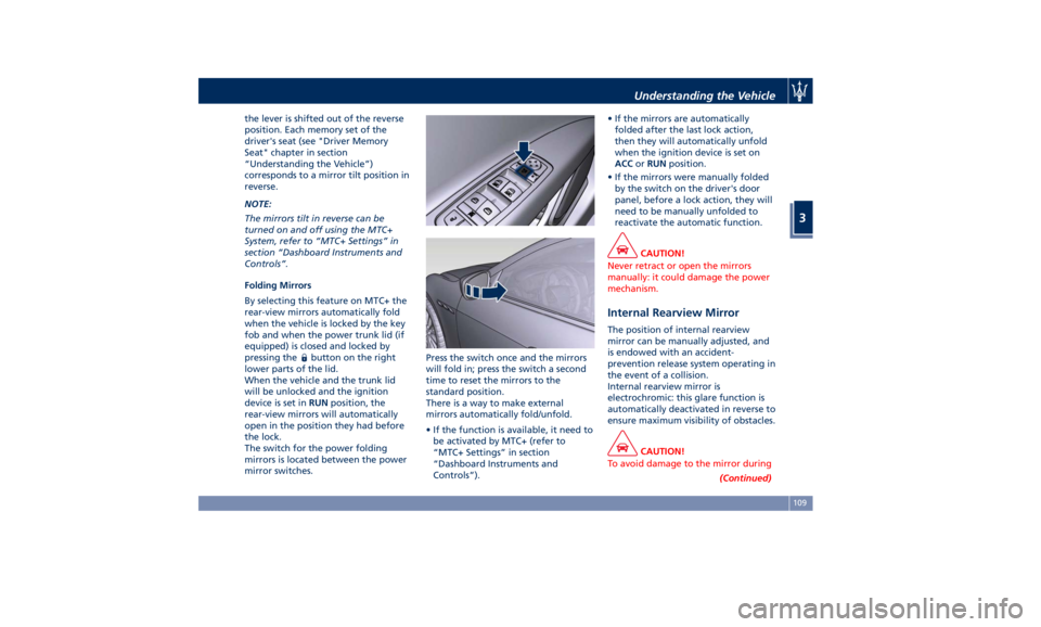
Folding Mirrors
By selecting this feature on MTC+ the
rear-view mirrors automatically fold
when the vehicle is locked by the key
fob and when the power trunk lid (if
equipped) is closed and locked by
pressing the
button on the right
lower parts of the lid.
When the vehicle and the trunk lid
will be unlocked and the ignition
device is set in RUN position, the
rear-view mirrors will automatically
open in the position they had before
the lock.
The switch for the power folding
mirrors is located between the power
mirror switches. Press the switch once and the mirrors
will fold in; press the switch a second
time to reset the mirrors to the
standard position.
There is a way to make external
mirrors automatically fold/unfold.
• If the function is available, it need to
be activated by MTC+ (refer to
“MTC+ Settings” in section
“Dashboard Instruments and
Controls”). • If the mirrors are automatically
folded after the last lock action,
then they will automatically unfold
when the ignition device is set on
ACC or RUN position.
• If the mirrors were manually folded
by the switch on the driver's door
panel, before a lock action, they will
need to be manually unfolded to
reactivate the automatic function.
CAUTION!
Never retract or open the mirrors
manually: it could damage the power
mechanism.
Internal Rearview Mirror The position of internal rearview
mirror can be manually adjusted, and
is endowed with an accident-
prevention release system operating in
the event of a collision.
Internal rearview mirror is
electrochromic: this glare function is
automatically deactivated in reverse to
ensure maximum visibility of obstacles.
CAUTION!
To avoid damage to the mirror during
(Continued)Understanding the Vehicle
3
109
Page 301 of 384
fumes, do not breathe close to the
fuel filler door, when opened.
• Never have any smoking materials
lit in or near the vehicle when the
fuel filler door is open or the tank is
being filled.
• Never add fuel when the engine is
running. This violates most
fire-prevention regulations and may
cause the Malfunction Indicator
Light
to turn on (see
“Instrument Cluster” in section
“Dashboard Instruments and
Controls”).
• Fill the vehicle with fuel. Fuel tank
capacity
is indicated in the
“Refillings” table in section
“Features and Specifications”.
When the fuel nozzle “clicks” or
shuts off, the fuel tank is basically
full: it is possible to further ensure
refueling by enabling the fuel nozzle
additional fuel supply until two
clicks. After the two additional clicks,
the amount of fuel allowed by the
system is very low, we recommend
therefore not to persist further.
• Wait approximately 10 seconds
before removing the fuel nozzle in
order to ensure completed supply of residual fuel and restrict the risk of
fouling the fuel filler door area.
• Remove the fuel nozzle.
• Close the fuel filler door.
CAUTION!
To avoid fuel spillage and overfilling,
do not “top off” the fuel tank after
filling.
Emergency Refueling Funnel
A
funnel is provided (in the trunk in
the tool box container) for emergency
refueling with a gas can. WARNING!
A fire may result if fuel is pumped
into a portable container that is inside
of a vehicle. You could be burned.
Always place gas containers outside
the vehicle while filling.
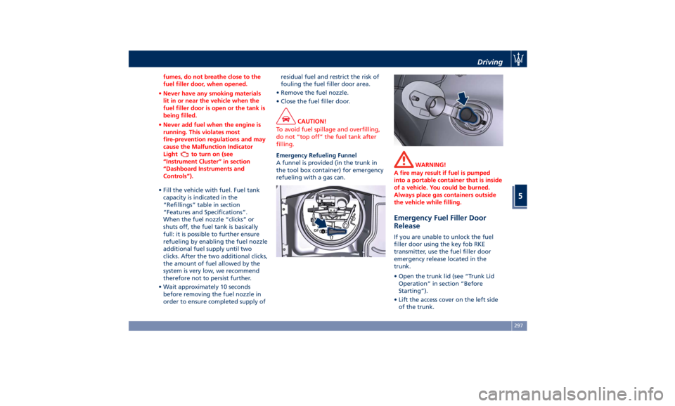
Emergency Fuel Filler Door
Release If you are unable to unlock the fuel
filler door using the key fob RKE
transmitter, use the fuel filler door
emergency release located in the
trunk.
• Open the trunk lid (see “Trunk Lid
Operation” in section “Before
Starting”).
• Lift the access cover on the left side
of the trunk.Driving
5
297
Page 302 of 384
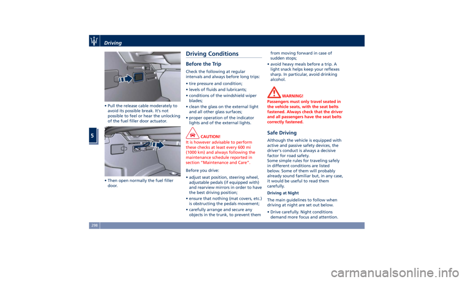
• Pull the release cable moderately to
avoid its possible break. It's not
possible to feel or hear the unlocking
of the fuel filler door actuator.
• Then open normally the fuel filler
door. Driving Conditions Before the Trip Check the following at regular
intervals and always before long trips:
• tire pressure and condition;
• levels of fluids and lubricants;
• conditions of the windshield wiper
blades;
• clean the glass on the external light
and all other glass surfaces;
• proper operation of the indicator
lights and of the external lights.
CAUTION!
It is however advisable to perform
these checks at least every 600 mi
(1000 km) and always following the
maintenance schedule reported in
section “Maintenance and Care”.
Before you drive:
•
adjust seat position, steering wheel,
adjustable pedals (if equipped with)
and rearview mirrors in order to have
the best driving position;
• ensure that nothing (mat covers, etc.)
is obstructing the pedals movement;
• carefully arrange and secure any
objects in the trunk, to prevent them from moving forward in case of
sudden stops;
• avoid heavy meals before a trip. A
light snack helps keep your reflexes
sharp. In particular, avoid drinking
alcohol.
WARNING!
Passengers must only travel seated in
the vehicle seats, with the seat belts
fastened. Always check that the driver
and all passengers have the seat belts
correctly fastened.
Safe Driving Although the vehicle is equipped with
active and passive safety devices, the
driver's conduct is always a decisive
factor for road safety.
Some simple rules for traveling safely
in different conditions are listed
below. Some of them will probably
already sound familiar but, in any case,
it would be useful to read them
carefully.
Driving at Night
The main guidelines to follow when
driving at night are set out below.
• Drive carefully. Night conditions
demand more focus and attention.Driving
5
298
Page 315 of 384
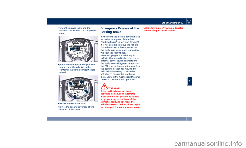
• wrap the power cable and the
inflation hose inside the compressor
case;
• place the compressor, the jack, the
wrench and the adapter in the
container inside the compact spare
wheel;
• reposition the other tools;
• lower the ground coverage at the
bottom of the trunk. Emergency Release of the
Parking Brake In the event the electric parking brake
locks due to a system failure (see
“Parking Brake” in section “Driving”),
it is not possible to move the vehicle,
since the actuator that operates on
the brake pad inside each rear caliper
will lock the rear wheels.
After verifying that the battery is
sufficiently charged (otherwise use an
external power source connected to
the vehicle electric system to operate
the EPB control lever and try to unlock
the parking brake), for moving the
vehicle it is necessary to force the
actuator to release the rear brake
discs. Contact the Authorized Maserati
Dealer to carry out this operation.
WARNING!
If the parking brake has been
activated in manual or automatic
mode and it is not possible to release
it by operating on the lever of the
central console, do not move the
vehicle since rear brake calipers might
be damaged. For more information on vehicle towing see "Towing a Disabled
Vehicle" chapter in this section.
In an Emergency
6
311
Page 317 of 384
CAUTION!
• To jump start a vehicle do not use a
portable battery, a booster pack or
any other booster source with a
system voltage greater than 14 Volts
or damage to the battery, starter
motor, alternator or electrical system
of the vehicle with the discharged
battery may occur.
• Do not use a battery charger for
emergency starting under any
circumstances. You could damage
the electronic systems, particularly
the control units managing the
ignition and fuel supply functions.
• If the battery is completely
discharged when the windows are
fully raised, open the door with the
utmost care; do not close the door
again until it is possible to lower the
window.
WARNING!
Always secure your vehicle by fully
applying the parking brake, before
activating the manual park release.
Activating the manual park release
could allow your vehicle to roll away if it is not secured by the parking
brake. Activating the manual park
release on an unsecured vehicle could
lead to serious injury or death for
those in or around the vehicle.
NOTE:
If
you need
to disconnect the battery
from the vehicle electrical system, see
“Maintenance — Free Battery” in
section “Maintenance and Care”).
WARNING!
California Proposition 65
Operating, servicing and maintaining
a passenger vehicle or off-road vehicle
can expose you to chemicals including
such as, engine exhaust, carbon
monoxide, phthalates and lead, that
which are known to the State of
California to cause cancer and birth
defects or other reproductive harm. To
minimize exposure, avoid breathing
exhaust, do not idle the engine except
as necessary, service your vehicle in a
well-ventilated area and wear gloves
or wash your hands frequently when
servicing your vehicle. For more
information go to: www.P65Warnings.ca.gov/passenger-
vehicle
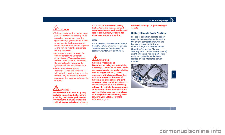
Battery Remote Posts Position For easier operation, remote battery
posts for jumpstarting are located in
the engine compartment while the
battery is stored in the trunk.
Open the engine hood (see “Hood
Operation” in section “Before
Starting”) the positive remote post (+)
and the negative remote post (-) are
easily recognizable by the icons
labeled on the integrated power
module.In an Emergency
6
313
Page 336 of 384
the Vehicle”) and move the ignition
switch to the RUN position: the wiper
arms will return to the resting
position.
NOTE:
Due to the difficulty of this operation,
we recommend that you contact an
Authorized Maserati Dealer for
replacement of the blades.
Maintenance-Free Battery This vehicle is equipped with a sealed
type maintenance-free battery. You
will never have to add water, nor is
periodic maintenance required.
WARNING!
• Battery fluid is a corrosive acid
solution and can burn or damage the
eyes. Do not allow battery fluid to
contact your eyes, skin, or clothing.
If acid splashes in eyes or on skin,
flush the area immediately with
large amounts of water.
• Battery gas is flammable and
explosive. Keep flame or sparks
away from the battery. Do not use a
booster battery or any other booster
source with an output greater than
12 Volts. Do not allow cable clamps
to touch each other.
• Battery posts, terminals, and related
accessories contain lead and lead
compounds. Wash hands after
handling the battery.
• The battery in this vehicle has a vent
hose that should not be
disconnected and should only be
replaced with a component of the same type (vented).
NOTE:
Remote
battery terminals for starting
are located in the engine
compartment for jump-starting to be
used with an auxiliary battery or a
battery from another vehicle (see
“Auxiliary Jump-Start Procedure”
chapter in section “In an Emergency”).
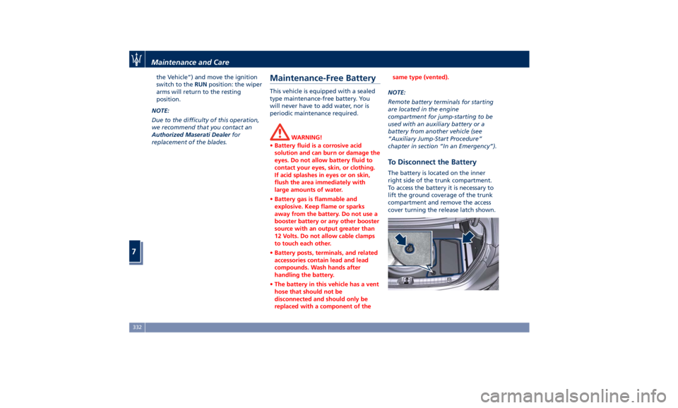
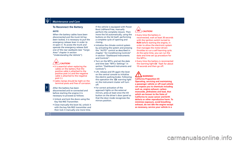
To Disconnect the Battery The battery is located on the inner
right side of the trunk compartment.
To access the battery it is necessary to
lift the ground coverage of the trunk
compartment and remove the access
cover turning the release latch shown.Maintenance and Care
7
332
Page 338 of 384
To Reconnect the Battery NOTE:
When the battery cables have been
disconnected and the trunk lid has
been locked, it is necessary to pull the
emergency release lever in order to
re-open it. To access the trunk and
operate the emergency release fold
one of the rear seatbacks (see “Cargo
Area” chapter in section
“Understanding the Vehicle”).
CAUTION!
• It is essential when replacing the
cables on the battery that the
positive cable is attached to the
positive post (+) and the negative
cable is attached to the negative
post (–).
• Cable clamps should be tight on the
terminal posts and free of corrosion.
After the battery has been
disconnected
and re-connected and
before starting the engine it is
necessary to proceed as follows:
• Unlock and lock the doors using the
Key fob RKE Transmitter.
• Close manually the boot lid, unlock it
with the key fob RKE transmitter and
then lock it manually one more time. If the vehicle is equipped with Power
Boot Lid/Hand Free, manually
perform the complete closure. Then
move the lid automatically, using the
buttons on the lid itself, performing
a complete cycle of opening and
closing.
• Initialize the climate control system
by activating the system and pressing
the “AUTO” control as described in
chapter “Air Conditioning Controls”
in section “Dashboard Instruments
and Controls”.
• Turn on the MTC+ and set the date
and time (see “MTC+ Settings” in
section “Dashboard Instruments and
Controls”).
• Lift, release and lift again the lever
on the central console to initialize
the electric parking brake. Following
this operation the
warning light
on the instrument cluster will turn
off.
• For correct activation of the
approach lights on the external
mirrors, press at least once the tilt
button on the driver's door panel so
that the door mode recognizes the
mirrors position. CAUTION!
• Every time the battery is
reconnected, wait at least 30 seconds
with the ignition switch turned to
RUN before starting the engine, in
order to allow the electronic system
that manages the motor-driven
throttles to run a self-learning cycle.
At the same time, you can run the
date and time set up procedure for
the MTC+.
• Every time the battery is reconnected
the warning light
flash for about
10 seconds and then go off.
WARNING!
California Proposition 65
Operating, servicing and maintaining
a passenger vehicle or off-road vehicle
can expose you to chemicals including
such as, engine exhaust, carbon
monoxide, phthalates and lead, that
which are known to the State of
California to cause cancer and birth
defects or other reproductive harm. To
minimize exposure, avoid breathing
exhaust, do not idle the engine except
as necessary, service your vehicle in aMaintenance and Care
7
334
Page 344 of 384
Ref. Type Function
36 Mini – 30A PCM module
primary load
37 Mini – 15A Engine secondary
load
38 Mini – 15A Lambda sensor
39 Mini – 7,5A Flow meters,
tank lackage,
canister, exhaust
by-pass valve and
relay coil
48 – –
49 Mini – 10A Pedal brake
switch - TCM
module
50 Mini – 15A +30 PCM module
51 Mini – 30A Fuel pump relay
input
52 Mini – 5A Starter solenoid
signal for PCM
and voltage
stabilizer
53 Mini – 10A AWD module
(AWD version
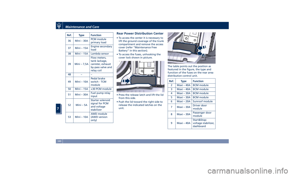
only) Rear Power Distribution Center • To access the center it is necessary to
lift the ground coverage of the trunk
compartment and remove the access
cover (refer “Maintenance Free
Battery” in this section).
• To access the fuses, unhooking the
cover lock shown in picture.
• Press the release latch and lift the lid
from this side.
• Push the lid toward the right side to
release the indicated latches on the
unit. The table points out the position as
featured in the figure, the type and
function of the fuses on the rear area
distribution control unit.
Ref. Type Function
2 Maxi – 40A BCM module
3 Maxi – 40A BCM module
4 Maxi – 30A BCM module
5 Maxi – 30A BCM module
6 Maxi – 20A Sunroof module
7 Maxi – 30A Driver door
module
8 Maxi – 30A Passenger door
module
9 Maxi – 40A Start&Stop:
voltage stabilizer,
dashboardMaintenance and Care
7
340