sensor MASERATI GHIBLI 2019 Workshop Manual
[x] Cancel search | Manufacturer: MASERATI, Model Year: 2019, Model line: GHIBLI, Model: MASERATI GHIBLI 2019Pages: 384, PDF Size: 13.33 MB
Page 283 of 384

• Lateral accelerations exceeds the
limits.
NOTE:
• When HAS cancels, the symbol
will turn red then grey.
• The presence of the hands on the
steering wheel is detected by a logic
combination of a capacitive sensor
installed in the steering wheel and
the measured applied torque at the
steering column. This leads to a
more robust hands detection.
System Limitations HAS is unable to guide the vehicle
when the following conditions occur.
• Lane markings are not clear or
visibility is poor (i.e. heavy rain,
snow, fog, etc.).
• Obstructed, covered or damaged
forward-facing camera or sensor.
• When driving on hills or sharp
curves.
• When approaching toll booths.
• When the highway entrance or exit
is wider than 20 ft (6 meters).
• Bright light (ex. direct sunlight or
glare) facing the forward camera. WARNING!
Many unforeseen conditions can occur
that can affect the performance of
Highway Assist (HAS). Always keep
this in mind and drive attentively. It is
the drivers responsibility to keep
control of the vehicle at all times.
Radar Device - Regulatory
Information The “Regulatory Information” for all
the radio frequency and radar devices
can be consulted by accessing the
“Services” section on the website
www.maserati.com.Traffic Sign Assist – TSA
(optional) TSA detects traffic signs through the
use of a forward-facing digital camera
mounted on windshield, behind the
rear-view mirror. TSA assists the driver
by displaying on the instrument
cluster detected speed limits and
traffic signs with a restriction
indicated by an additional sign (e.g. in
snow conditions). TSA also uses the
data of the navigation system, in
order to provide information to the
driver in all cases in which the camera
is not able to detect the traffic signs
that are present on the road where
the car is travelling.
Some examples of these are: due to
low visibility, light reflection, damaged
traffic signs, traffic signs in wrong
position like rotated or fallen poles.
NOTE:
• Overtaking restriction signs are not
displayed by the TSA system.
• TSA provides a visual warning to the
driver when he/she unintentionally
reaches the maximum speed limit
allowed or when it exceeds the set
“Sensitivity” value.
(Continued)Driving
5
279
Page 291 of 384

overall conditions should also be
checked monthly. Tire pressures
change by approximately 1 PSI (0.07
bar) per 12°F (7°C) of air temperature
change. Keep this in mind when
checking tire pressure inside a garage,
especially in winter.
Example: If garage temperature = 68°F
(20°C) and the outside temperature =
32°F (0°C) then the cold tire inflation
pressure should be increased by 3 PSI
(0.21 bar) for every 12°F (7°C) for this
outside temperature condition.
Tire pressure may increase from 2 to 6
PSI (0.13 to 0.4 bar) during operation.
DO NOT reduce this normal pressure
build-up or your tire pressure will be
too low. After inspecting or adjusting
the tire pressure, always reinstall the
valve stem cap. This will prevent
moisture and dirt from entering the
valve stem, which could damage the
valve stem and the TPMS sensor
connected to it.
Tread Wear Indicators Tread wear indicators are in the
original equipment tires to help you
determine when your tires should be
replaced.
These indicators are molded into the
bottom of the tread grooves. When the tread is worn to one of the
tread wear indicators, the tire should
be replaced.
WARNING!
The wet performance (aquaplaning
resistance) will decrease
proportionally to the thickness of the
tread.
Tires Durability The service life of a tire depends on
various factors including, but not
limited to:
• driving style;
• tire pressure;
• distance driven.
WARNING!
Tires and the spare tire (if equipped)
should be replaced after six years,
regardless of the remaining tread.
Failure to follow this warning could
result in tire failure. Replacement Tires NOTE:
In order to maintain high performance
and safety level under all driving
conditions, Maserati strongly
recommends to use tires equivalent to
the originals in size, quality and
performance when replacement is
needed.
For the size designation of your tire
see the label on the driver's side rear
door pillar or see table “Wheels” in
section “Features and Specifications”.
The “Load Index” and “Speed
Symbol” for your tire will be found on
the original equipment tire sidewall.
NOTE:
Maserati recommends Maserati
Genuine Tires marked with “MGT”
logo specifically designed for its
models.
It is recommended to replace the two
front tires or two rear tires as a pair.
Replacing just one tire can seriously
affect your vehicle’s handling.
If you ever replace a wheel assembly,
make sure that the wheel’s
specifications (valve, TPMS sensor and
tire) match those of the original
wheels. Failure to use equivalentDriving
5
287
Page 294 of 384

off until the tire pressure is equal or
above the recommended cold inflation
pressure. Once the low tire pressure
warning light
illuminates, you must
increase the tire pressure to the
recommended cold inflation pressure
in order for the TPMS light
to turn
off. The system will automatically
update and the TPMS light
will turn
off once the system acquires the
correct tire pressure.
The vehicle may need to be driven for
up to 20 minutes above 15 mph
(24 km/h) in order for the TPMS to
acquire and process the updated
setting. WARNING!
The TPMS warns the driver that the
tire pressure has decreased. This
warning does not exempt the driver
from periodically checking the tires
and from complying with the
prescribed tire pressure levels.
CAUTION!
• The TPMS has been optimized for the
original equipment tires and wheels.
TPMS pressures and warning have
been established for the tire size
equipped on your vehicle.
Undesirable system operation or
sensor damage may occur when
using replacement equipment that is
not of the same size, type, and/or
style. Aftermarket wheels can cause
sensor damage. Do not use aftermarket tire sealants or balance
beads if your vehicle is equipped
with a TPMS, as damage to the
sensors may result.
• The system can temporarily
experience radio-electric
interference emitted by devices
using similar frequencies.
• After inspecting or adjusting the tire
pressure, always reinstall the valve
stem cap. This will prevent moisture
and dirt from entering the valve
stem and damage the TPMS internal
sensor.
NOTE:
• Driving
on a
significantly
underinflated tire causes the tire to
overheat and may lead to tire failure.
Under-inflation also reduces fuel
efficiency and tire tread life, and may
affect the vehicle’s handling and
stopping ability.
• The TPMS is not a substitute for
proper tire maintenance, and it is the
driver’s responsibility to maintain
correct tire pressure using an
accurate tire pressure gage, even if
under-inflation has not reached the
level to trigger illumination of the
TPMS light
.
• Seasonal temperature changes will
affect tire pressure, and the TPMSDriving
5
290
Page 295 of 384

will monitor the actual tire pressure
in the tire.
Premium System The TPMS system uses wireless
technology with wheel rim mounted
electronic sensors to monitor tire
pressure levels. Sensors mounted to
each wheel as part of the valve stem
transmit tire pressure readings to the
receiver module.
The TPMS consists of the following
components:
• receiver module;
• four TPMS sensors;
• various TPMS messages, which
display on the instrument cluster;
• warning light
.
Tire Pressure Low Warning
The TPMS light will illuminate in
the instrument cluster and an acoustic
signal will notify that tire pressure is
low in one or more of the four tires. The instrument cluster will also display
a screenshot reporting the pressure
values of each tire with flashing low
pressure value.
Should this occur, you should stop as
soon as possible and inflate the tire/s
with the low pressure (the one/s
flashing in the instrument cluster
graphic) to the recommended cold
pressure inflation value. Once the
system receives the updated tire
pressure value, the system will automatically update, the graphic
display in the instrument cluster will
stop flashing, and the TPMS light
will turn off. The vehicle may need
to be driven for up to 20 minutes
above 15 mph (24 km/h) in order for
the TPMS to acquire and process the
updated information.
Tire Pressure System Fault
If a system fault is detected, the TPMS
light
will flash for 75 seconds and
then remain lit followed by a beeping
sound. Therewith, the instrument
cluster will display a "Service Tire
Pressure System" message for a
minimum of five seconds and then
display dashes (--) in place of the
pressure value to indicate which
sensor is ineffective.
If the ignition switch is cycled, the
sequence will repeat, in case the
system fault still persists. If the system
fault no longer exists, the TPMS light
will no longer flash, and the
"Service Tire Pressure System"
message will no longer be displayed,
and a pressure value will be displayed
in place of the dashes.
A system fault can occur due to any of
the following:
• Signal interference due to electronic
devices or driving next to facilitiesDriving
5
291
Page 296 of 384

emitting the same radio frequencies
as the TPMS sensors.
• Installing aftermarket window
tinting that contains materials that
may block radio wave signals.
• Accumulation of snow or ice around
the wheels or wheel housings.
• Using tire chains on the vehicle.
• Using wheels/tires not equipped with
TPMS sensors.
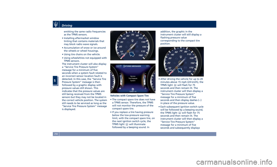
The instrument cluster will also display
a "Service Tire Pressure System"
message for a minimum of five
seconds when a system fault related to
an incorrect sensor location fault is
detected. In this case, the "Service Tire
Pressure System" message is then
followed by a graphic display with
pressure values still shown. This
indicates that the pressure values are
still being received from the TPMS
sensors but they may not be located in
the correct vehicle position. The system
still needs to be serviced as long as the
"Service Tire Pressure System" message
is displayed. Vehicles with Compact Spare Tire
• The compact spare tire does not have
a TPMS sensor. Therefore, the TPMS
will not monitor the pressure of the
compact spare tire.
• If you replace a tire having pressure
below the low-pressure warning
limit, with the compact spare tire, on
the next ignition switch cycle, the
TPMS light
will illuminate
followed by a beeping sound. In addition, the graphic in the
instrument cluster will still display a
flashing pressure value
corresponding to the compact tire
position.
• After driving the vehicle for up to 20
minutes above 15 mph (24 km/h), the
TPMS light
will flash for 75
seconds and then remain lit. The
instrument cluster will then display a
"Service Tire Pressure System"
message for a minimum of five
seconds and then display dashes (--)
in place of the pressure value.
• Each subsequent ignition switch cycle
will be followed by a beeping sound,
the TPMS light
will flash for 75
seconds and then remain lit. The
instrument cluster will then display a
"Service Tire Pressure System"
message for a minimum of five
seconds and subsequently displaysDriving
5
292
Page 297 of 384

dashes (--) in place of the pressure
value.
• Once you repair, replace or reinstall
a tire with the compact spare tire,
the TPMS will update automatically.
The TPMS light
will turn OFF and
the graphic in the instrument cluster
will display a new pressure value
instead of dashes (--), as long as no
tire pressure is below the
low-pressure warning limit in any of
the four tires. The vehicle may need
to be driven for up to 20 minutes
above 15 mph (24 km/h) in order for
the TPMS to acquire and process the
updated information.
TPMS Deactivation The TPMS can be deactivated if
replacing all four tire rims with wheel
and tire assemblies not using of TPMS
sensors, such as winter wheel and tire assemblies. After replacing all four
wheel and tire assemblies (road tires)
with tires not equipped with Tire
Pressure Monitoring System sensors,
drive the vehicle for 20 minutes above
15 mph (24 km/h). The TPMS will
chime, the TPMS light
will flash on
and off for 75 seconds and then
remain on and the instrument cluster
will display the “Service Tire Pressure
System” message and then display
dashes (--) in place of the pressure
values. Beginning with the next
ignition switch cycle, the TPMS will no
longer chime or display the “Service
Tire Pressure System” message in the
instrument cluster but dashes (--) will
remain in place of the pressure values.
To reactivate the TPMS, replace all
four wheel and tire assemblies (road
tires) with tires equipped with TPMS
sensors. Then, drive the vehicle for up to 20 minutes above 15 mph
(24 km/h). The TPMS will chime, the
TPMS light
will flash for 75 seconds
and then turn off. The instrument
cluster will then display the “Service
Tire Pressure System” message.
The instrument cluster will also display
pressure values in place of the dashes
(--). On the next ignition switch cycle
the “Service Tire Pressure System”
message will no longer be displayed as
long as no system fault exists.
Radio Frequency Transmitter -
Regulatory Information The “Regulatory Information” for all
the radio and radar frequency devices
can be consulted by accessing the
“Services” section on the website
www.maserati.com.Driving
5
293
Page 335 of 384

CAUTION!
Failure to replace the filter may
considerably reduce the air
conditioning and heating system
efficiency.
Wiper Maintenance and Blades
Replacement Windshield Wiper Arms Lifting
When the windshield wiper arms are
in rest position it is not possible to
check or replace the blades as they
remain under the engine hood.
To service the blades it is necessary to
move the wiper arms in “Service”
position (see chapter “Wipers and
Washers” in section “Understanding
the Vehicle”). In this way it is possible
to lift the arms for cleaning or
replacing the wiper blades.
WARNING!
It is dangerous to operate or service
the wiper blades with the windshield
wipers in an active position (any
position different from “OFF”) and
with the ignition switch in the RUN
position. The rain sensors may
suddenly activate the wipers. Always use the “Service” position for any
intervention on the windshield wiper
blades.
Windshield Wiper Maintenance
Life
expectancy of
wiper blades varies
depending on the geographical area’s
weather conditions where the car is
used and frequency of use. Poor
performance of blades may be present
with chattering, marks on the glass,
water lines or wet spots. If any of
these conditions are present, clean the
wiper blades or replace if necessary.
Clean the rubber edges of the wiper
blades and the windshield/rear
window glasses periodically with a
sponge or soft cloth and a mild
nonabrasive cleaner. This will remove
accumulations of salt or road film.
Operation of the wipers on dry glass
for long periods may cause
deterioration of the wiper blades.
Always use washer fluid when using
the wipers to remove salt or dirt from
a dry windshield.
Avoid using the wiper blades to
remove frost or ice from the
windshield. Keep the blade rubber out
of contact with petroleum products
such as engine oil, gasoline, etc. Spray nozzles
If the jet does not work, first check
that there is fluid in the tank (see
paragraph “Level checks” in this
section) then check that the nozzles
are not clogged.
Windshield Wiper Blades Replacement
• Move the wiper arms into “Service”
position, (see chapter “Windshield
Wipers and Washers” in section
“Understanding the Vehicle”) and
lift them.
• Press the indicated button, slip off
the blade support from the arm and
replace it.
• Return the blade to its original
position on the windshield.
• Turn the multifunction lever to one
of the automatic settings (see
chapter “Windshield Wipers and
Washers” in section “UnderstandingMaintenance and Care
7
331
Page 340 of 384

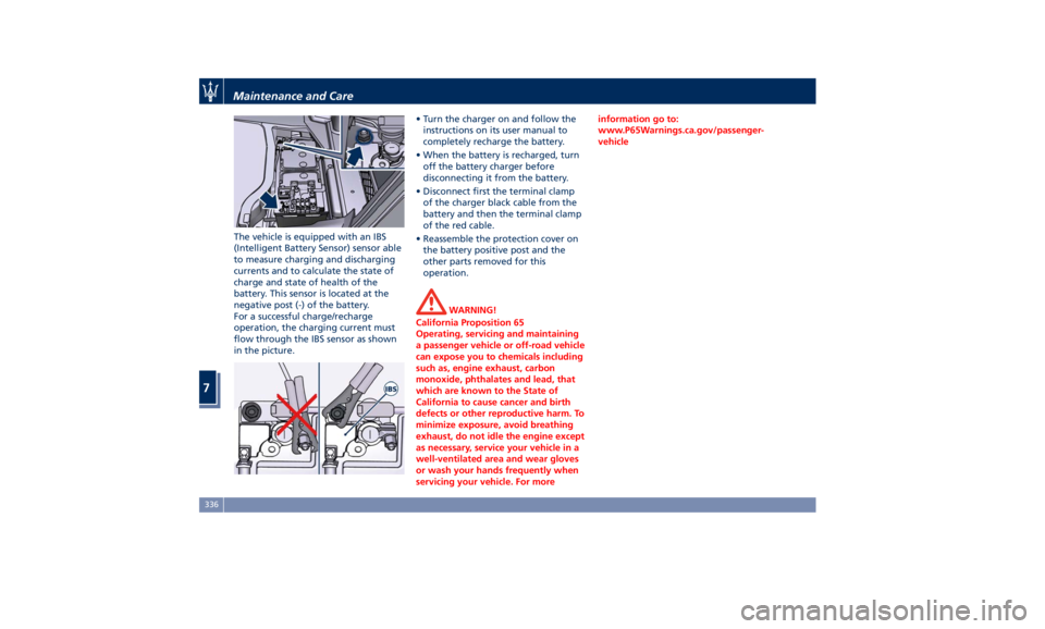
The vehicle is equipped with an IBS
(Intelligent Battery Sensor) sensor able
to measure charging and discharging
currents and to calculate the state of
charge and state of health of the
battery. This sensor is located at the
negative post (-) of the battery.
For a successful charge/recharge
operation, the charging current must
flow through the IBS sensor as shown
in the picture. • Turn the charger on and follow the
instructions on its user manual to
completely recharge the battery.
• When the battery is recharged, turn
off the battery charger before
disconnecting it from the battery.
• Disconnect first the terminal clamp
of the charger black cable from the
battery and then the terminal clamp
of the red cable.
• Reassemble the protection cover on
the battery positive post and the
other parts removed for this
operation.
WARNING!
California Proposition 65
Operating, servicing and maintaining
a passenger vehicle or off-road vehicle
can expose you to chemicals including
such as, engine exhaust, carbon
monoxide, phthalates and lead, that
which are known to the State of
California to cause cancer and birth
defects or other reproductive harm. To
minimize exposure, avoid breathing
exhaust, do not idle the engine except
as necessary, service your vehicle in a
well-ventilated area and wear gloves
or wash your hands frequently when
servicing your vehicle. For more information go to:
www.P65Warnings.ca.gov/passenger-
vehicle
Maintenance and Care
7
336
Page 344 of 384

Ref. Type Function
36 Mini – 30A PCM module
primary load
37 Mini – 15A Engine secondary
load
38 Mini – 15A Lambda sensor
39 Mini – 7,5A Flow meters,
tank lackage,
canister, exhaust
by-pass valve and
relay coil
48 – –
49 Mini – 10A Pedal brake
switch - TCM
module
50 Mini – 15A +30 PCM module
51 Mini – 30A Fuel pump relay
input
52 Mini – 5A Starter solenoid
signal for PCM
and voltage
stabilizer
53 Mini – 10A AWD module
(AWD version
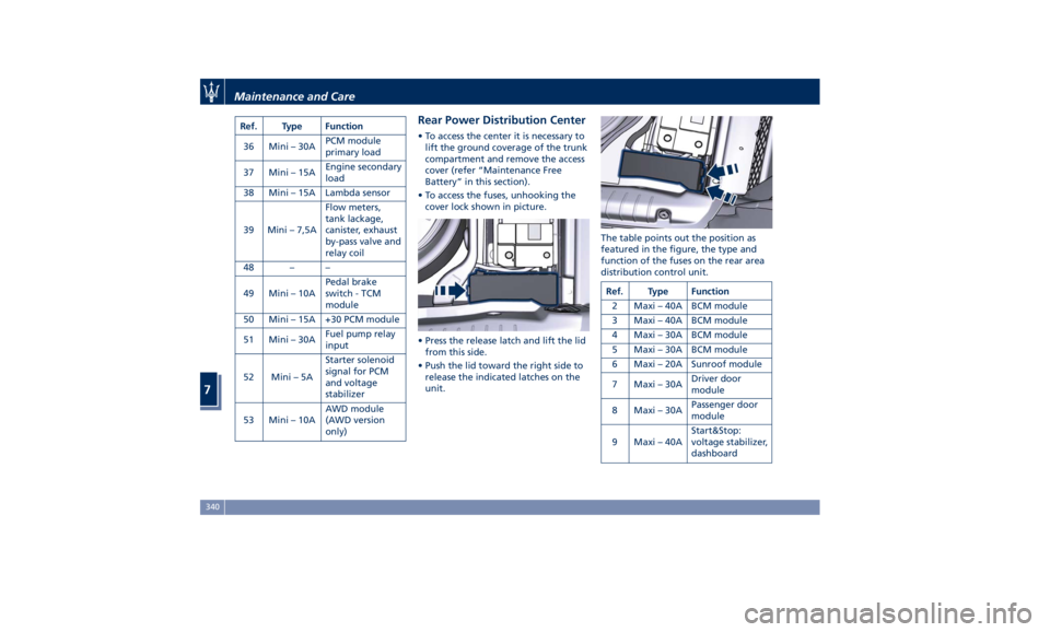
only) Rear Power Distribution Center • To access the center it is necessary to
lift the ground coverage of the trunk
compartment and remove the access
cover (refer “Maintenance Free
Battery” in this section).
• To access the fuses, unhooking the
cover lock shown in picture.
• Press the release latch and lift the lid
from this side.
• Push the lid toward the right side to
release the indicated latches on the
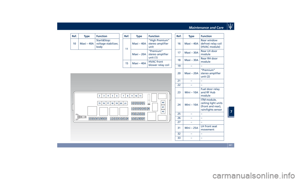
unit. The table points out the position as
featured in the figure, the type and
function of the fuses on the rear area
distribution control unit.
Ref. Type Function
2 Maxi – 40A BCM module
3 Maxi – 40A BCM module
4 Maxi – 30A BCM module
5 Maxi – 30A BCM module
6 Maxi – 20A Sunroof module
7 Maxi – 30A Driver door
module
8 Maxi – 30A Passenger door
module
9 Maxi – 40A Start&Stop:
voltage stabilizer,
dashboardMaintenance and Care
7
340
Page 345 of 384

Ref. Type Function
10 Maxi – 40A Start&Stop:
voltage stabilizer,
body Ref. Type Function
11 Maxi – 40A “High Premium”
stereo amplifier
unit
Maxi – 20A “Premium”
stereo amplifier
unit (1)
15 Maxi – 40A HVAC front
blower relay coil Ref. Type Function
16 Maxi – 40A Rear window
defrost relay coil
(HVAC module)
17 Maxi – 30A Rear LH door
module
18 Maxi – 30A Rear RH door
module
19 – –
20 Maxi – 20A “Premium”
stereo amplifier
unit (2)
21 – –
22 – –
23 Mini – 10A Fuel door relay
and RF Hub
module
24 Mini – 10A ITM module,
ceiling light units
(front and rear),
rain/lights sensor
25 – –
26 – –
27 – –
31 Mini – 25A LH front seat
movement
32 – –
33 – –Maintenance and Care
7
341