hood release MASERATI GHIBLI 2019 Owners Manual
[x] Cancel search | Manufacturer: MASERATI, Model Year: 2019, Model line: GHIBLI, Model: MASERATI GHIBLI 2019Pages: 384, PDF Size: 13.33 MB
Page 41 of 384
How to use Remote Start All of the following conditions must
be met before the engine will remote
start:
• System not disabled from previous
remote start event.
• Vehicle theft alarm not active.
• Doors closed.
• Hood closed.
• Trunk lid closed.
• Hazard lights switched off.
• Brake pedal not pressed.
• Battery at an acceptable charge
level.
• The shift lever is in P (Park) position.
• The vehicle transmission is in
automatic mode.
• The remote start has not been
activated yet two consecutive times.
If EPB (Electric Parking Brake) is not
selected, at key-off in some conditions
the remote start system may not allow
engine to start. We suggest to set
“Auto Apply On” function through
the switch on the right-side of the
steering wheel (refer to “Instrument
Cluster” in section “Dashboard
Instrument and Controls”). WARNING!
• Do not start or run an engine in a
closed garage or confined area.
Exhaust gas contains Carbon
Monoxide (CO) which is odorless
and colorless
• Keep key fobs RKE transmitter away
from children. Operation of the
Remote Start System, windows,
door locks or other controls could
cause serious injury or death.
Engine Remote Start Abort
Message on Instrument Cluster The following messages will display on
the instrument cluster if the vehicle
fails to remote start or exits remote
start prematurely:
• “Remote Start Canceled Door
Open”.
• “Remote Start Canceled Trunk
Open”.
• “Remote Start Canceled Fuel Low”.
• “Remote Start Canceled Time
Expired”.
• “Remote Start Disabled Start Vehicle
to Reset”. The message on the instrument cluster
stays active as long as the ignition
switch is in RUN position.
To enter Remote Start Mode Press and release the button on the
key fob RKE transmitter twice within
five seconds. The vehicle doors will
lock, position lights will flash and the
horn will ring twice (if this function is
set using the MTC+ System, refer to
“MTC+ Settings” in section
“Dashboard Instruments and
Controls”). Then, the engine will start
and the vehicle will remain in the
“Remote Start” mode for a 15-minute
cycle.
WARNING!
California Proposition 65
Operating, servicing and maintaining
a passenger vehicle or off-road vehicle
can expose you to chemicals including
such as, engine exhaust, carbon
monoxide, phthalates and lead, that
which are known to the State of
California to cause cancer and birth
defects or other reproductive harm. To
minimize exposure, avoid breathing
exhaust, do not idle the engine except
as necessary, service your vehicle in a
(Continued)Before Starting
2
37
Page 58 of 384
Trunk Safety WARNING!
Do not allow children to have access
to the trunk. Always close the trunk
lid when your vehicle is unattended.
Once in the trunk, young children may
not be able to escape. If trapped in the
trunk, children can die from
suffocation or heat stroke.
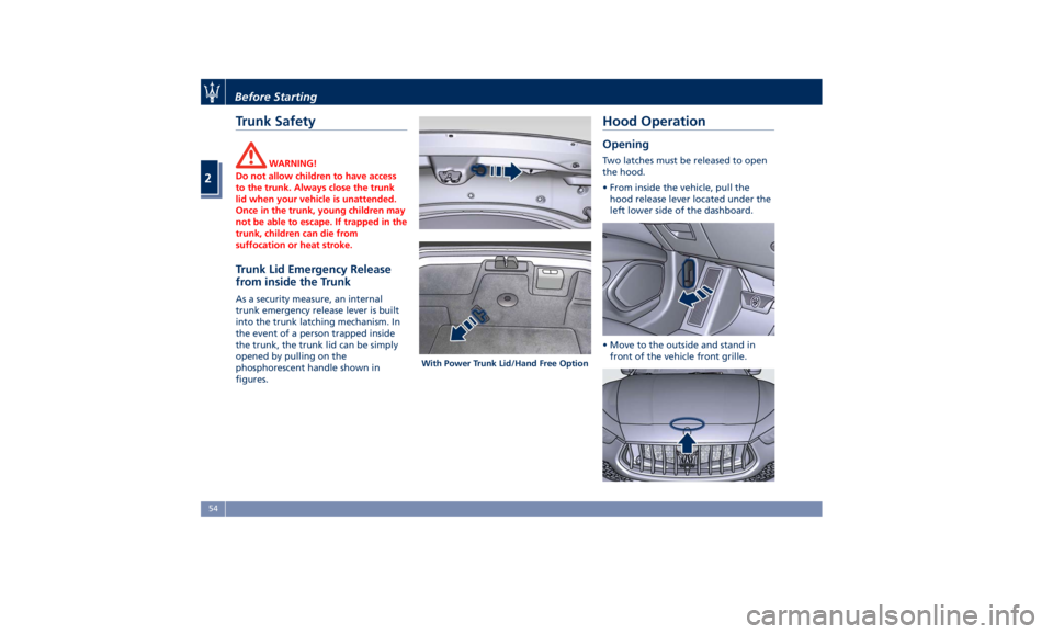
Trunk Lid Emergency Release
from inside the Trunk As a security measure, an internal
trunk emergency release lever is built
into the trunk latching mechanism. In
the event of a person trapped inside
the trunk, the trunk lid can be simply
opened by pulling on the
phosphorescent handle shown in
figures. Hood Operation Opening Two latches must be released to open
the hood.
• From inside the vehicle, pull the
hood release lever located under the
left lower side of the dashboard.
• Move to the outside and stand in
front of the vehicle front grille.With Power Trunk Lid/Hand Free OptionBefore Starting
2
54
Page 97 of 384
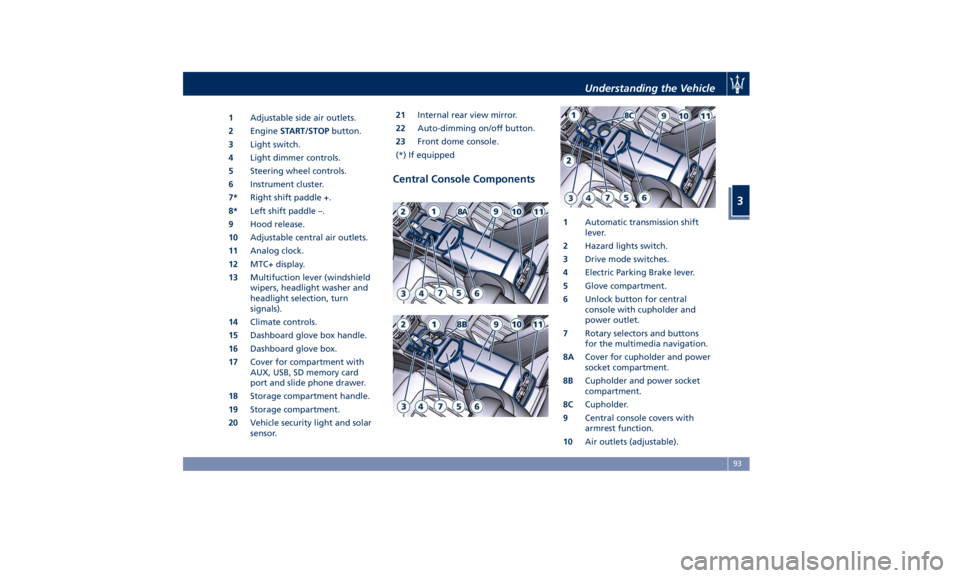
1 Adjustable side air outlets.
2 Engine START/STOP button.
3 Light switch.
4 Light dimmer controls.
5 Steering wheel controls.
6 Instrument cluster.
7* Right shift paddle +.
8* Left shift paddle –.
9 Hood release.
10 Adjustable central air outlets.
11 Analog clock.
12 MTC+ display.
13 Multifuction lever (windshield
wipers, headlight washer and
headlight selection, turn
signals).
14 Climate controls.
15 Dashboard glove box handle.
16 Dashboard glove box.
17 Cover for compartment with
AUX, USB, SD memory card
port and slide phone drawer.
18 Storage compartment handle.
19 Storage compartment.
20 Vehicle security light and solar
sensor. 21 Internal rear view mirror.
22 Auto-dimming on/off button.
23 Front dome console.
(*) If equipped
Central Console Components 1 Automatic transmission shift
lever.
2 Hazard lights switch.
3 Drive mode switches.
4 Electric Parking Brake lever.
5 Glove compartment.
6 Unlock button for central
console with cupholder and
power outlet.
7 Rotary selectors and buttons
for the multimedia navigation.
8A Cover for cupholder and power
socket compartment.
8B Cupholder and power socket
compartment.
8C Cupholder.
9 Central console covers with
armrest function.
10 Air outlets (adjustable).Understanding the Vehicle
3
93
Page 128 of 384
arms. It will not operate under the
following conditions:
• Low Temperature Wipe Inhibit : the
rain sensing feature will not operate
when the ignition is in RUN position,
the vehicle is stationary and the
outside temperature is below 32°F
(0°C). To resume, set the automatic
feature on the multifunction lever,
start the engine and drive or wait
until the outside temperature rises
above freezing.
• Wipe Inhibit with Transmission in
Neutral Position : the rain sensing
feature will not operate when the
ignition is placed in the RUN
position, the transmission shift lever
is in the N (Neutral) position and the
vehicle speed is less than 5 mph
(8 km/h). To resume, set the
multifunction lever to the automatic
function or move the shift lever out
of N (Neutral).
Headlights On with Windshield
Wipers When activating this function, the
headlights will light up approximately
10 seconds after the wipers acting on
the windshield are turned on if the
light switch is placed in “AUTO”
position. In addition, the headlights switch off when the wipers are turned
off (position “OFF”) if they were
previously turned by using this
function. Powering on Headlights with
wipers can be activated and
deactivated with the MTC+ System, see
“MTC+ Settings” in section
“Dashboard Instruments and Controls”
for further information.
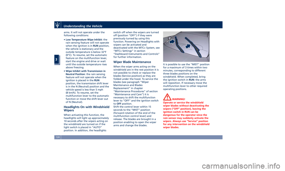
Wiper Blade Maintenance When the wiper arms acting on the
windshield are in the rest position it is
not possible to check or replace the
blades (Service position) as they are
folded under the hood. To service the
blades (see paragraph “Wiper
Maintenance and Blades
Replacement” in chapter
“Maintenance Procedures” of section
“Maintenance and Care”) it is
necessary to shift the multifunction
lever to “OFF” and the ignition switch
to OFF position.
Shift the control lever within 15
seconds to the “MIST” position
(forward rotation of the end of the
multifunction control lever) and
release. The blades are brought in a
position enabling to open the wiper
arms and change the blades. It is possible to use the “MIST” position
for a maximum of 3 times within two
minutes, corresponding to different
three blades positions on the
windshield. When completed, bring
the ignition switch in RUN : the arms
will reposition. If necessary move the
multifunction lever to other required
operating positions.
WARNING!
Operate or service the windshield
wiper blades without deactivating the
wipers (“OFF” position), leaving the
ignition switch in RUN can be
dangerous for the operator since the
rain sensor may suddenly activate the
wipers. Always use “Service” position
for any intervention on the windshield
wiper blades.Understanding the Vehicle
3
124
Page 216 of 384
released, when one of the following
conditions occurs:
• The SPORT drive mode or (ESC
OFF) drive mode is being activated.
• If the Start&Stop function has been
disabled through the main menu
voice “Start & Stop” (see chapter
“Instrument cluster” in section
“Dashboard Instruments and
Controls”) or through the Start&Stop
hard button on the central console
(see chapter “Drive Mode” in this
section) or via MTC+ in the “Control”
page (see “MTC+ ”Control” Screen”
in section “Dashboard Instruments
and Controls”).
• If shift lever is moved to R (Reverse).
• If the steering wheel is moved to
steer the wheels.
• When the temperature conditions
inside the vehicle do not correspond
to the air conditioning setting.
• When changing the temperature
setting on the air conditioning.
• When the defroster function is being
activated.
• When the battery charge is below
safety value.
• When the accelerator pedal is being
pressed (together with the brake
pedal). • If a long time has passed since the
last automatic stop of the engine.
Occupants Safety Function To enhance occupants safety, the
Start&Stop system monitors if the
driver is present and does not allow
automatic restarting of the engine if
one of the following maneuvers is
being performed while in “AutoStop”
condition:
• The driver unbuckles his/her seat belt
and releases the brake pedal.
• The driver opens the door and
releases the brake pedal.
• The driver unbuckles the seat belt
and opens the door.
• The driver opens the hood.
All the above-mentioned conditions
deactive the Start&Stop function (the
“AutoStart” is deactivated and the
engine remains off) and the
transmission shifts automatically in P
(Park).
The
telltale will flash to indicate
the Start&Stop function disabling. To
restart the engine it is necessary to
press the brake pedal and push the
START/STOP button.
Move the shift lever to D (Drive) to
drive away. WARNING!
• Even when the vehicle is stopped in
the “Stop (AutoStop)” phase, the
driver is responsible for the vehicle
and the occupants and shall take
care of what happens inside and
outside the vehicle.
• Even when the vehicle is stopped
within the “Stop (AutoStop)” phase,
the vehicle driver is responsible for
the vehicle, the vehicle’s occupants
and the vehicle’s surrounding area.
Never leave the vehicle unattended
with the engine running; doing so
poses a risk of danger. It is a good
practice to always ensure to set the
parking brake and place the
transmission gear selector lever into
the P (Park) position, thereby
ensuring the vehicle will not move,
when performing any vehicle checks,
maintenance and/or service
procedures on the vehicle.
Start&Stop Function Disabling Start & Stop enabled is the default
status.
Under certain driving conditions, when
frequent stops and restarts of the
engine may become annoying, it isDriving
5
212
Page 317 of 384
CAUTION!
• To jump start a vehicle do not use a
portable battery, a booster pack or
any other booster source with a
system voltage greater than 14 Volts
or damage to the battery, starter
motor, alternator or electrical system
of the vehicle with the discharged
battery may occur.
• Do not use a battery charger for
emergency starting under any
circumstances. You could damage
the electronic systems, particularly
the control units managing the
ignition and fuel supply functions.
• If the battery is completely
discharged when the windows are
fully raised, open the door with the
utmost care; do not close the door
again until it is possible to lower the
window.
WARNING!
Always secure your vehicle by fully
applying the parking brake, before
activating the manual park release.
Activating the manual park release
could allow your vehicle to roll away if it is not secured by the parking
brake. Activating the manual park
release on an unsecured vehicle could
lead to serious injury or death for
those in or around the vehicle.
NOTE:
If
you need
to disconnect the battery
from the vehicle electrical system, see
“Maintenance — Free Battery” in
section “Maintenance and Care”).
WARNING!
California Proposition 65
Operating, servicing and maintaining
a passenger vehicle or off-road vehicle
can expose you to chemicals including
such as, engine exhaust, carbon
monoxide, phthalates and lead, that
which are known to the State of
California to cause cancer and birth
defects or other reproductive harm. To
minimize exposure, avoid breathing
exhaust, do not idle the engine except
as necessary, service your vehicle in a
well-ventilated area and wear gloves
or wash your hands frequently when
servicing your vehicle. For more
information go to: www.P65Warnings.ca.gov/passenger-
vehicle
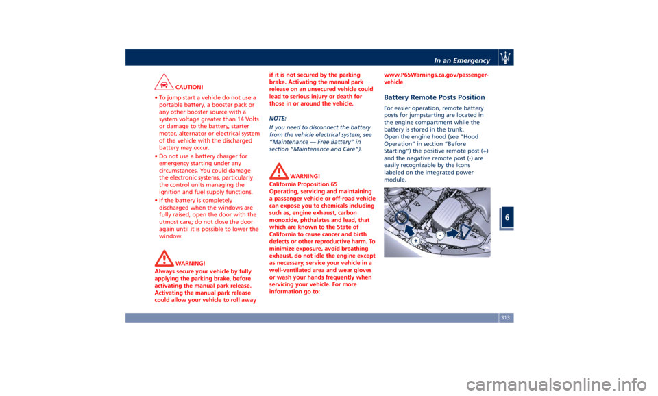
Battery Remote Posts Position For easier operation, remote battery
posts for jumpstarting are located in
the engine compartment while the
battery is stored in the trunk.
Open the engine hood (see “Hood
Operation” in section “Before
Starting”) the positive remote post (+)
and the negative remote post (-) are
easily recognizable by the icons
labeled on the integrated power
module.In an Emergency
6
313
Page 377 of 384
Clock, analog .............. .186
Console
Central Console Components ....93
Front Dome Console
Components ...............94
Controls Screen ............. .179
Cruise Control
Cruise Control Adaptive (ACC) . .247
Electronic Cruise Control (CC) . . .244
Cupholders ................ .127
Front Passengers Cupholders . . .127
Rear Passengers Cupholders . . .128
Dashboard Compartment ...... .194
Dashboard Components .........92
Defroster ...................47
Doors
Child Protection Door Lock
System ...................40
Doors Locking ..............39
Doors Manual Lock ...........39
Front Doors Components ......94
Lock/Unlock Door Flashlight ....33
Power Doors Locking/Unlocking . .39
Rear Doors Components .......95
Soft Door Close System ........41
Unlock Driver Door/All Doors with
Remote Key 1st Press .........33
DPF System
DPF Filter Replacement ...... .328
“Drive Away Inhibit” strategy . . . .237
Drive Mode, controls ......... .224
Setting the Drive Mode ...... .224 Driving Conditions ........... .298
Before the Trip ............ .298
Driving at Night ........... .298
Driving in Fog ............ .299
Driving in the Mountains ..... .300
Driving in the Rain ......... .299
Driving on Snow or Ice ...... .300
Safe Driving .............. .298
DRL (Daytime Running Light) . . . .113
EDR (Event Data Recorder) .......71
Electronic Cruise Control ....... .244
Emergency ...................5
Hazard Warning Lights ...... .121
In the Event of an Accident . . . .305
Jump Starting ............ .312
Trunk Lid Emergency Release ....53
Engine
Engine Coolant Level Check . . . .325
Engine Oil Level Check ......
.328
Hood ....................
5 4
Normal
Starting of the Engine . .208
Use of the Engine .......... .242
Entry/Exit, lights on ............30
EPB (Electric Parking Brake) ..... .233
ESC (Electronic Stability Control) . .238
Filters
A/C System Air Filter
Replacement ............. .330
Engine Air Filter Replacement . .330
Forward Collision Warning (FCW) . .258 Fuel
Carbon Monoxide Warning . . . .295
Emergency Fuel Filler Door
Release ................. .297
Emissions Inspection and
Maintenance Programs ...... .323
Fuel Consumption ......... .363
Fuel Filter Service .......... .328
Fuel Requirements ......... .294
Fuel System Warnings ....... .295
Gasoline/Oxygenate Blends . . . .294
Low Fuel Indicator ......... .166
Materials Added to Fuel ..... .295
MMT in Gasoline .......... .295
Reformulated Gasoline ...... .294
Fuses .................... .337
Fuses Position ............ .337
Fuses Replacement ......... .337
Glove Box Feature Lock (Passenger
Side) ................... .195
Glove Box Lock Feature
Handholds and Cloth Hooks . . . .131
Hazard Warning Flashers ...... .305
Head Restraints ...............96
Highway Assist - HAS ......... .274
HomeLink ................. .138
Security ................. .141
Troubleshooting Tips ........ .141
Using HomeLink ........... .141
Hood
Open and Close the Hood ......54Index
9 373