parking brake MASERATI GHIBLI 2019 Owners Manual
[x] Cancel search | Manufacturer: MASERATI, Model Year: 2019, Model line: GHIBLI, Model: MASERATI GHIBLI 2019Pages: 384, PDF Size: 13.33 MB
Page 13 of 384
ECU Electronic Control Unit.
EDR Event Data Recorder.
EPB Electric Parking Brake.
ESC Electronic Stability Control.
ETC Electronic Throttle Control.
FCW Forward Collision Warning.
HAS Highway Assist.
HSA Hill Start Assist.
HBA Hydraulic Brake Assistance.
I.C.E. Increased Control and
Efficiency.
LATCH Lower Anchors and Tether
for Children.
LDW Lane Departure Warning
(LaneSense).
LKA Lane Keeping Assist.
MIL Malfunction Indicator
Light.
MTC+ Maserati Touch Control
Plus.
OBD On Board Diagnostics.
ORC Occupant Restraint
Controller.
PDC Park Distance Control.
PEB Pedestrian Emergency
Braking.
RAB Ready Alert Braking. RCP Rear Cross Path.
RKE Remote Keyless Entry.
SAB Side Air Bag.
SABIC Supplemental Side Air Bag
Inflatable Curtains.
SBR Seat Belt Reminder.
SRS Supplemental Restraint
System.
TCS Traction Control System.
TFT Thin Film Transistor.
TPMS Tire Pressure Monitoring
System.
TSA Traffic Sign Assist.
VIN Vehicle Identification
Number.Updating Constant improvements are being
performed to maintain this vehicle's
high level of quality. Therefore, there
may be differences between this
manual and your vehicle.
Maserati reserves the right to carry
out design and functional changes
and to provide updates or
improvements.
This Owner's Manual illustrates and
describes all versions of the current
vehicle model. Therefore, some of the
equipment and accessories in this
publication may not appear on your
vehicle; please only consider the
information related to your vehicle.
All specifications and illustrations
contained in this manual are as of the
Manual publishing date.
NOTE:
The updated version of the on-board
documentation can be consulted by
accessing the section “Services” on the
website www.maserati.com .Introduction
1
9
Page 30 of 384
(Continued)
others could be seriously or fatally
injured. Children should be warned
not to touch the parking brake
trigger, brake pedal or the shift
lever.
• Do not leave the key fob in or near
the vehicle, and do not leave the
ignition switch in the ACC or RUN
mode. A child could operate power
windows, other controls, or move
the vehicle.
• Do not leave children or animals
inside parked vehicles in hot
weather. Interior heat build-up may
cause serious injury or death.
• An unlocked car is an invitation to
thieves. Always remove the key fob
from vehicle, cycle the ignition
switch to OFF and lock all doors
when leaving the vehicle
unattended. Sentry Key ®
Immobilizer
System The Sentry Key ®
Immobilizer System
prevents unauthorized vehicle
operation by disabling the engine. The
system does not need to be armed or
activated. Operation is automatic,
regardless of whether the vehicle is
locked or unlocked.
The system uses a key fob with Remote
Keyless Entry (RKE) transmitter, an
ignition switch and a RF (Radio
Frequency) receiver to prevent
unauthorized vehicle operation.
Therefore, only key fobs expressly
programmed can be used to start and
operate the vehicle.
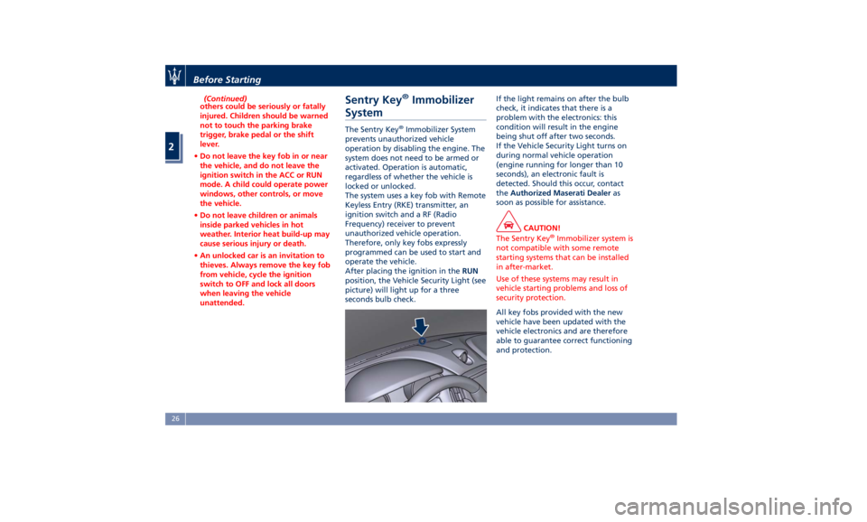
After placing the ignition in the RUN
position, the Vehicle Security Light (see
picture) will light up for a three
seconds bulb check. If the light remains on after the bulb
check, it indicates that there is a
problem with the electronics: this
condition will result in the engine
being shut off after two seconds.
If the Vehicle Security Light turns on
during normal vehicle operation
(engine running for longer than 10
seconds), an electronic fault is
detected. Should this occur, contact
the Authorized Maserati Dealer as
soon as possible for assistance.
CAUTION!
The Sentry Key ®
Immobilizer system is
not compatible with some remote
starting systems that can be installed
in after-market.
Use of these systems may result in
vehicle starting problems and loss of
security protection.
All key fobs provided with the new
vehicle
have been updated with the
vehicle electronics and are therefore
able to guarantee correct functioning
and protection.Before Starting
2
26
Page 41 of 384
How to use Remote Start All of the following conditions must
be met before the engine will remote
start:
• System not disabled from previous
remote start event.
• Vehicle theft alarm not active.
• Doors closed.
• Hood closed.
• Trunk lid closed.
• Hazard lights switched off.
• Brake pedal not pressed.
• Battery at an acceptable charge
level.
• The shift lever is in P (Park) position.
• The vehicle transmission is in
automatic mode.
• The remote start has not been
activated yet two consecutive times.
If EPB (Electric Parking Brake) is not
selected, at key-off in some conditions
the remote start system may not allow
engine to start. We suggest to set
“Auto Apply On” function through
the switch on the right-side of the
steering wheel (refer to “Instrument
Cluster” in section “Dashboard
Instrument and Controls”). WARNING!
• Do not start or run an engine in a
closed garage or confined area.
Exhaust gas contains Carbon
Monoxide (CO) which is odorless
and colorless
• Keep key fobs RKE transmitter away
from children. Operation of the
Remote Start System, windows,
door locks or other controls could
cause serious injury or death.
Engine Remote Start Abort
Message on Instrument Cluster The following messages will display on
the instrument cluster if the vehicle
fails to remote start or exits remote
start prematurely:
• “Remote Start Canceled Door
Open”.
• “Remote Start Canceled Trunk
Open”.
• “Remote Start Canceled Fuel Low”.
• “Remote Start Canceled Time
Expired”.
• “Remote Start Disabled Start Vehicle
to Reset”. The message on the instrument cluster
stays active as long as the ignition
switch is in RUN position.
To enter Remote Start Mode Press and release the button on the
key fob RKE transmitter twice within
five seconds. The vehicle doors will
lock, position lights will flash and the
horn will ring twice (if this function is
set using the MTC+ System, refer to
“MTC+ Settings” in section
“Dashboard Instruments and
Controls”). Then, the engine will start
and the vehicle will remain in the
“Remote Start” mode for a 15-minute
cycle.
WARNING!
California Proposition 65
Operating, servicing and maintaining
a passenger vehicle or off-road vehicle
can expose you to chemicals including
such as, engine exhaust, carbon
monoxide, phthalates and lead, that
which are known to the State of
California to cause cancer and birth
defects or other reproductive harm. To
minimize exposure, avoid breathing
exhaust, do not idle the engine except
as necessary, service your vehicle in a
(Continued)Before Starting
2
37
Page 43 of 384
Doors Locking WARNING!
• For personal security and safety,
always lock the vehicle doors before
you drive as well as when parking
and leaving the vehicle unattended.
• When leaving the vehicle, always
remove the key fob RKE transmitter
and lock your vehicle.
• Never leave children alone in a
vehicle, or with access to an
unlocked vehicle.
• Do not allow children to be in a
vehicle unattended. A child or
others could be seriously or fatally
injured. Children must not touch the
parking brake trigger, brake pedal or
the shift lever.
• Do not leave the key fob in or near
the vehicle, and do not leave
ignition switch in the ACC or RUN
mode.
Doors Manual Lock To lock each door, push the door lock
knob on each door trim panel
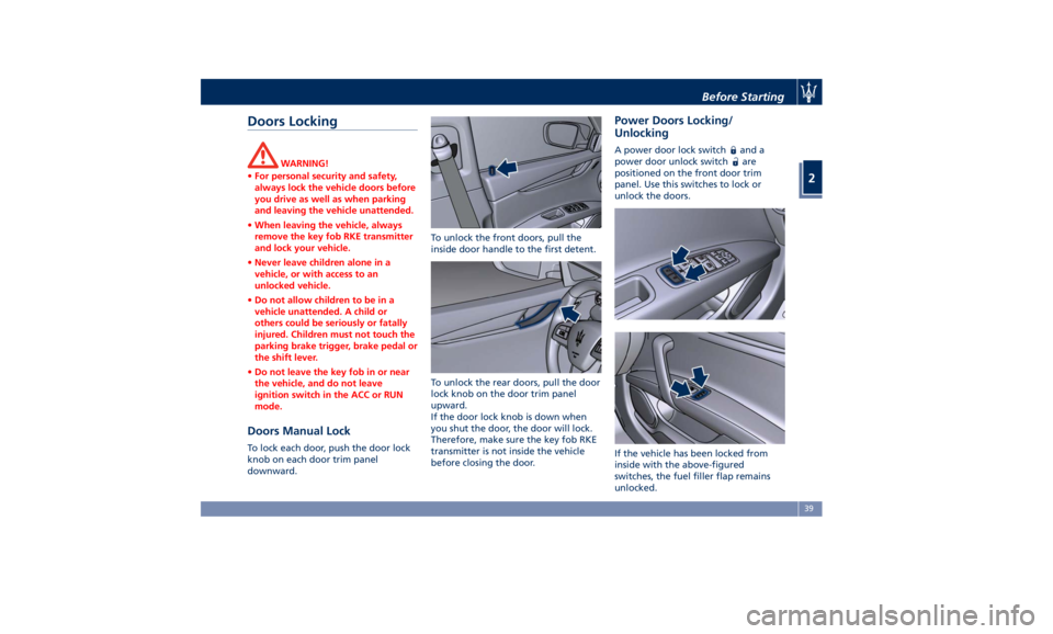
downward. To unlock the front doors, pull the
inside door handle to the first detent.
To unlock the rear doors, pull the door
lock knob on the door trim panel
upward.
If the door lock knob is down when
you shut the door, the door will lock.
Therefore, make sure the key fob RKE
transmitter is not inside the vehicle
before closing the door. Power Doors Locking/
Unlocking A power door lock switch and a
power door unlock switch
are
positioned on the front door trim
panel. Use this switches to lock or
unlock the doors.
If the vehicle has been locked from
inside with the above-figured
switches, the fuel filler flap remains
unlocked.Before Starting
2
39
Page 92 of 384
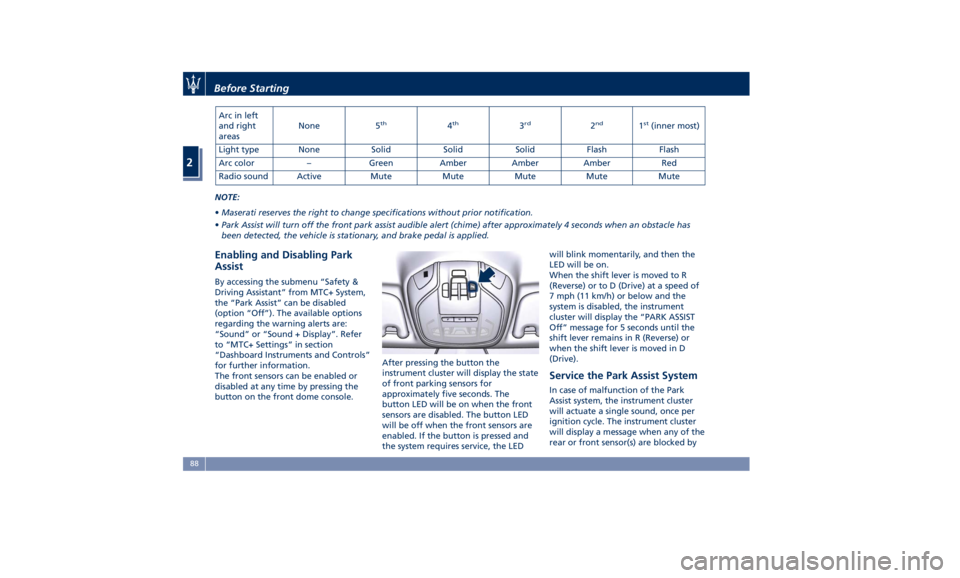
Arc in left
and right
areas None 5 th
4 th
3 rd
2 nd
1 st
(inner most)
Light type None Solid Solid Solid Flash Flash
Arc color – Green Amber Amber Amber Red
Radio sound Active Mute Mute Mute Mute Mute
NOTE:
• Maserati reserves the right to change specifications without prior notification.
• Park Assist will turn off the front park assist audible alert (chime) after approximately 4 seconds when an obstacle has
been detected, the vehicle is stationary, and brake pedal is applied.
Enabling and Disabling Park
Assist By accessing the submenu “Safety &
Driving Assistant” from MTC+ System,
the “Park Assist” can be disabled
(option “Off”). The available options
regarding the warning alerts are:
“Sound” or “Sound + Display”. Refer
to “MTC+ Settings” in section
“Dashboard Instruments and Controls”
for further information.
The front sensors can be enabled or
disabled at any time by pressing the
button on the front dome console. After pressing the button the
instrument cluster will display the state
of front parking sensors for
approximately five seconds. The
button LED will be on when the front
sensors are disabled. The button LED
will be off when the front sensors are
enabled. If the button is pressed and
the system requires service, the LED will blink momentarily, and then the
LED will be on.
When the shift lever is moved to R
(Reverse) or to D (Drive) at a speed of
7 mph (11 km/h) or below and the
system is disabled, the instrument
cluster will display the “PARK ASSIST
Off” message for 5 seconds until the
shift lever remains in R (Reverse) or
when the shift lever is moved in D
(Drive).
Service the Park Assist System In case of malfunction of the Park
Assist system, the instrument cluster
will actuate a single sound, once per
ignition cycle. The instrument cluster
will display a message when any of the
rear or front sensor(s) are blocked byBefore Starting
2
88
Page 97 of 384
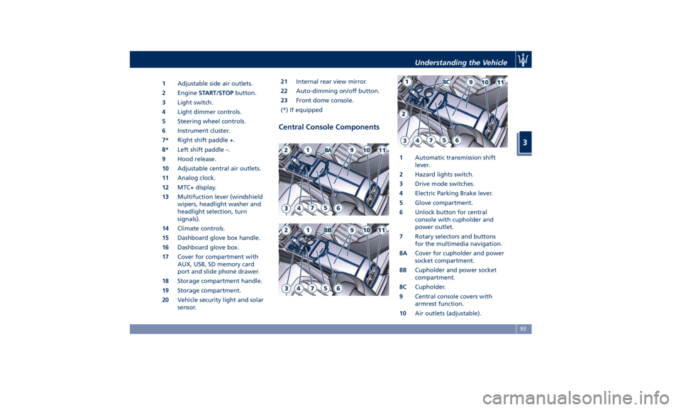
1 Adjustable side air outlets.
2 Engine START/STOP button.
3 Light switch.
4 Light dimmer controls.
5 Steering wheel controls.
6 Instrument cluster.
7* Right shift paddle +.
8* Left shift paddle –.
9 Hood release.
10 Adjustable central air outlets.
11 Analog clock.
12 MTC+ display.
13 Multifuction lever (windshield
wipers, headlight washer and
headlight selection, turn
signals).
14 Climate controls.
15 Dashboard glove box handle.
16 Dashboard glove box.
17 Cover for compartment with
AUX, USB, SD memory card
port and slide phone drawer.
18 Storage compartment handle.
19 Storage compartment.
20 Vehicle security light and solar
sensor. 21 Internal rear view mirror.
22 Auto-dimming on/off button.
23 Front dome console.
(*) If equipped
Central Console Components 1 Automatic transmission shift
lever.
2 Hazard lights switch.
3 Drive mode switches.
4 Electric Parking Brake lever.
5 Glove compartment.
6 Unlock button for central
console with cupholder and
power outlet.
7 Rotary selectors and buttons
for the multimedia navigation.
8A Cover for cupholder and power
socket compartment.
8B Cupholder and power socket
compartment.
8C Cupholder.
9 Central console covers with
armrest function.
10 Air outlets (adjustable).Understanding the Vehicle
3
93
Page 153 of 384
When the engine starts again, the
telltale will switch off.
If the telltale during an automatic
engine shutdown (AutoStop) phase
starts flashing, it will be necessary to
restart the engine normally with the
ignition device while holding down
the brake pedal.
See chapter “Normal Starting of the
Engine” in section “Driving” for
further information.
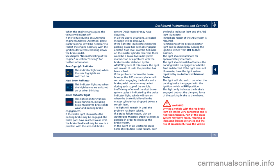
Rear Fog Light Indicator
This indicator lights up when
the rear fog lights are
switched on.
High Beam Indicator
This indicator lights up when
the high beams are switched
on or when blinking.
Brake Indicator Light
This light monitors various
brake functions, including
brake fluid level, brake pads
wear and parking brake
engagement.
If the brake light illuminates the
parking brake may be engaged, the
brake pads have reached wear limit,
the brake fluid level may be low or a
problem with the anti-lock brake system (ABS) reservoir may have
occurred.
In all the above situations, a related
message will be displayed.
If the light still illuminates when the
parking brake has been disengaged,
and the fluid level is at the full mark
on the master cylinder reservoir, there
could be a brake hydraulic system
malfunction or a problem with the
brake booster detected by the
ABS/ESC system. If this occurs, the light
will remain lit until the problem has
been solved.
If the problem concerns the brake
booster, the ABS master cylinder will
run when engaging the brake and a
brake pedal pulsation may be felt
during each stop of the vehicle.
Inefficiency of one of the dual brake
system cycles is indicated by the brake
indicator light, which will turn on
when the brake fluid level in the
master cylinder has dropped below a
certain level.
The light will remain lit until the
problem has been solved.
If a brake failure occurs, visit an
Authorized Maserati Dealer as soon as
possible in order to check up the
brake system.
In the event of an Electronic Brake
Force Distribution (EBD) failure, both the brake indicator light and the ABS
light illuminate.
Immediate repair of the ABS system is
required.
Functioning of the brake indicator
light can be checked by turning the
ignition switch from OFF to RUN
position.
The light should illuminate for
approximately 2 seconds.
The light should switch off unless the
parking brake is engaged or a brake
fault is detected. If the light does not
illuminate, have the light system
repaired by an Authorized Maserati
Dealer .
The light will also switch on when the
parking brake is engaged with the
ignition switch in RUN position.
This light only indicates the brake is
engaged but not the clamping force
of the parking brake to the wheels.
WARNING!
Driving a vehicle with the red brake
light on can be very dangerous and is
not recommended. Part of the brake
system may have failed, resulting in
increased braking distances and the
risk of an accident. Have the vehicleDashboard Instruments and Controls
4
149
Page 155 of 384
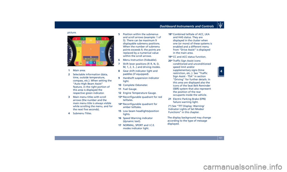
picture.
1 Main area.
2 Selectable information (data,
time, outside temperature,
compass, etc.). When setting the
“Auto High Beam Assist”
feature, in the right portion of
this area is displayed the
respective green indicator.
3 Main menu titles with scroll
arrows (the number and the
main menu title is always visible
while scrolling the menu, and for
the next five seconds).
4 Submenu Titles. 5 Position within the submenus
and scroll arrows (example: 1 of
5). There can be maximum 9
displayable submenu positions.
When the number of submenu
points exceeds 9, the points are
replaced by a numerical value
within the scroll arrows.
6 Menu Instruction (hideable).
7 Shift lever positions (P, R, N, D,
M, 1, 2, 3...) and driving modes.
8 Gear shift indicator light and
paddles (if equipped).
9 Hard/soft suspension indicator
light.
10 Complete Odometer.
11 Fuel Gauge.
12 Engine Temperature Gauge.
13* Reconfigurable quadrant for red
telltales.
14* Reconfigurable quadrant for
amber telltales.
15 Low beam headlights/position
lights.
16 Speed Warning indicator
(dynamic text).
17 NORMAL, SPORT and I.C.E.
modes indicator light. 18* Combined telltale of ACC, LKA
and HAS status. They are
displayed in the cluster when
one (or more) of these systems is
enabled and a different menu
from “Drive Assist” is displayed
in the main area.
19* CC and ACC status function.
20* Traffic Sign Assist icons:
conditioned and unconditioned
speed limit and/or
supplementary signs (time
restriction, etc..). See "Traffic
Sign Assist - TSA" in section
"Driving" for further details. In
this area are displayed also the
icons of the Seat Belt Reminder
(SBR) system that also represent
the position of the rear
occupants inside the vehicle.
21 Electric Parking Brake (EPB)
failure warning light.
(*) See “TFT Display: Warning/
Indicator Lights of Set Modes/
Functions” in this chapter.
The display background may change
according to the type of message
displayed.Dashboard Instruments and Controls
4
151
Page 157 of 384
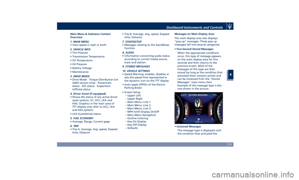
Main Menu & Submenu Content
Overview
1. MAIN MENU
• View speed in mph or km/h
2. VEHICLE INFO
• Tire Pressure
• Transmission Temperature
• Oil Temperature
• Oil Pressure
• Battery Voltage
• Maintenance
3. DRIVE MODE
• Drive Mode - Torque Distribution (on
AWD version only) - Powertrain
status - ESC status - Suspension
stiffness status
4. Driver Assist (if equipped)
• Shows the status of any active driver
assist systems: CC, ACC, LKA and
HAS. Graphics in the main area of
TFT display only refer to ACC, LKA
and HAS systems
• LKA (LaneSense) status
5. FUEL ECONOMY
• Average, Range, Current gage
6. TRIP
• Trip A: Average, Avg. speed, Elapsed
time, Distance • Trip B: Average, Avg. speed, Elapsed
time, Distance
7. START&STOP
• Messages relating to the Start&Stop
function
8. AUDIO
• Information concerning audio status
according to current media source,
track and station.
9. STORED MESSAGES
10. VEHICLE SETTINGS
• Speed Warning: enables, disables or
sets the speed limit represented in
the dynamic icon on the TFT display
• Auto apply Off/On of the Electric
Parking Brake
• Screen Setup
– Upper Left
– Upper Right
– Main Menu: Line 1
– Main Menu: Line 2
– Main Menu: Line 3
– MPH km/h Display On/Off
– Main Menu Navigation
– Outline Coloring
– Key-On Display
– Key-Off Display
– Defaults Messages on Main Display Area
The main display area also displays
"pop up" messages. These pop up
messages fall into several categories:
• Five-Second Stored Messages
When the appropriate conditions
occur, this type of message appears
on the main display area for five
seconds and then returns to the
previous screen. Most of the
messages of this type are then
stored (as long as the condition that
activated them remains active) and
can be reviewed from the "Stored
Messages" main menu item.
Example of this message type is the
one shown in the picture.
• Unstored Messages
This message type is displayed until
the condition that activated theDashboard Instruments and Controls
4
153
Page 164 of 384
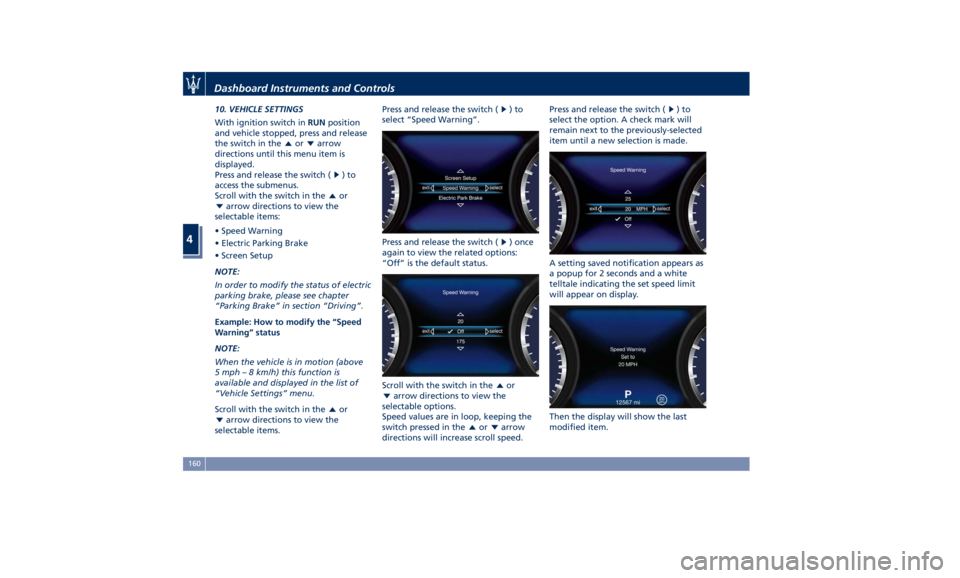
10. VEHICLE SETTINGS
With ignition switch in RUN position
and vehicle stopped, press and release
the switch in the or arrow
directions until this menu item is
displayed.
Press and release the switch (
)to
access the submenus.
Scroll with the switch in the
or
arrow directions to view the
selectable items:
• Speed Warning
• Electric Parking Brake
• Screen Setup
NOTE:
In order to modify the status of electric
parking brake, please see chapter
“Parking Brake” in section “Driving”.
Example: How to modify the “Speed
Warning” status
NOTE:
When the vehicle is in motion (above
5 mph – 8 km/h) this function is
available and displayed in the list of
“Vehicle Settings” menu.
Scroll with the switch in the
or
arrow directions to view the
selectable items. Press and release the switch (
)to
select “Speed Warning”.
Press and release the switch (
) once
again to view the related options:
“Off” is the default status.
Scroll with the switch in the
or
arrow directions to view the
selectable options.
Speed values are in loop, keeping the
switch pressed in the
or arrow
directions will increase scroll speed. Press and release the switch ( )to
select the option. A check mark will
remain next to the previously-selected
item until a new selection is made.
A setting saved notification appears as
a popup for 2 seconds and a white
telltale indicating the set speed limit
will appear on display.
Then the display will show the last
modified item.Dashboard Instruments and Controls
4
160