power steering MASERATI GHIBLI 2019 Owners Manual
[x] Cancel search | Manufacturer: MASERATI, Model Year: 2019, Model line: GHIBLI, Model: MASERATI GHIBLI 2019Pages: 384, PDF Size: 13.33 MB
Page 42 of 384
(Continued)
well-ventilated area and wear gloves
or wash your hands frequently when
servicing your vehicle. For more
information go to:
www.P65Warnings.ca.gov/passenger-
vehicle
NOTE:
• In
case of an engine fault or low fuel
level, the vehicle will start and then
shut down in 10 seconds.
• The position lights will turn on and
remain lighted up during “Remote
Start” mode.
• For security reasons, power window
and power sunroof operation are
disabled when the vehicle is in the
“Remote Start” mode.
• The engine can be started two
consecutive times (two 15-minute
cycles) with the key fob RKE transmitter. However, the ignition
must be cycled to the RUN position
before you can repeat the start
sequence for a third cycle.
To exit Remote Start Mode
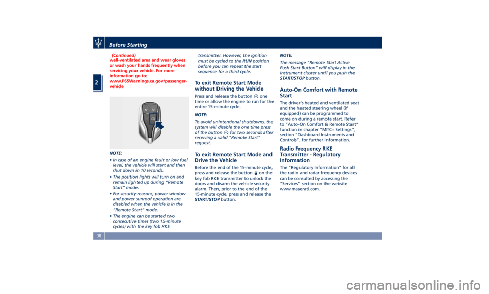
without Driving the Vehicle Press and release the button one
time or allow the engine to run for the
entire 15-minute cycle.
NOTE:
To avoid unintentional shutdowns, the
system will disable the one time press
of the button
for two seconds after
receiving a valid “Remote Start”
request.
To exit Remote Start Mode and
Drive the Vehicle Before the end of the 15-minute cycle,
press and release the button
on the
key fob RKE transmitter to unlock the
doors and disarm the vehicle security
alarm. Then, prior to the end of the
15-minute cycle, press and release the
START/STOP button. NOTE:
The message “Remote Start Active
Push Start Button” will display in the
instrument cluster until you push the
START/STOP button.
Auto-On Comfort with Remote
Start The driver's heated and ventilated seat
and the heated steering wheel (if
equipped) can be programmed to
come on during a remote start. Refer
to “Auto-On Comfort & Remote Start”
function in chapter “MTC+ Settings”,
section “Dashboard Instruments and
Controls”, for further information.
Radio Frequency RKE
Transmitter - Regulatory
Information The “Regulatory Information” for all
the radio and radar frequency devices
can be consulted by accessing the
“Services” section on the website
www.maserati.com.Before Starting
2
38
Page 69 of 384
• Supplemental Side Air Bag Inflatable
Curtains (SABIC);
• Front and side impact sensors;
• Front seat belt pretensioners;
• Seat belt buckle switch;
• Seat track position sensors;
• Pyrotechnical charge to cut power
from the battery; it is located on the
positive battery terminal.
WARNING!
The air bag is not a substitute for the
seat belts. Correct use of the seat
belts, in combination with the air bag,
will offer protection for the driver and
passenger in the front seat in the
event of a head-on collision.
Advanced Front Air Bags
Properties The advanced front air bag system has
multistage driver and front passenger
air bags. This system provides air bag
inflation rates which are appropriate
to the severity and type of collision as
determined by the Occupant Restraint
Controller (ORC), which may receive
information from the front impact
sensors. The first stage inflator is triggered
immediately during an impact that
requires air bag deployment. This
inflation rate is used in less severe
collisions. A higher energy output,
inflation rate, is used for more severe
collisions.
CAUTION!
• The airbag system must be ready to
protect you in a collision. The
Occupant Restraint Controller (ORC)
monitors the internal circuits and
interconnecting wiring associated with
electrical Air Bag System Components
listed below:
– Occupant Restraint Controller
(ORC)
– Airbag Warning light on the
instrument cluster
– Steering Wheel and Column
– Instrument Cluster
– Driver advanced front air bag
– Passenger advanced front air bag
– Supplemental Seat-Mounted Side
Air Bags (SAB) Air Bags
– Supplemental Side Air Bag
Inflatable Curtains (SABIC)
– Front and side Impact Sensors
– Front seat belt pretensioners
– Seat Belt Buckle Switch – Seat Track Position Sensors
– Pyrotechnical charge to cut the
power from the battery: it is
located on the positive battery
terminal
• The electronic control unit provides
for the activation of the
pretensioners, front air bags or side
air bags (front and rear) based on
different criteria, according to the
type of impact. Failure of one or
more systems to activate is not
indicative of a system malfunction.
• The front and/or lateral air bags may
inflate if the vehicle suffers a violent
impact involving the underbody
area, for example in case of violent
impacts against steps, sidewalks,
speed bumps, or when the vehicle
falls into potholes, or similar.
WARNING!
• No objects should be placed over or
near the air bag on the instrument
panel or steering wheel because any
such objects could cause harm if the
vehicle is in a collision severe
enough to cause the air bag to
inflate.
(Continued)Before Starting
2
65
Page 73 of 384
quantity of nontoxic gas is generated
to inflate the advanced front air bags.
The steering wheel hub trim cover and
the upper right side of the dashboard
separate and fold out of the way as
the air bags inflate to their full size.
The air bags then quickly deflate while
helping to restrain the driver and
front passenger. The advanced front
air bag gas is vented through the vent
holes in the sides of the air bag. In this
way, the air bags do not interfere with
your control of the vehicle.
Supplemental Driver Side Knee Air
Bag Inflator Unit
The supplemental driver side knee air
bag unit is located in the dashboard
trim beneath the steering column.
When the ORC detects a collision
requiring the air bag, it signals the
inflator units. A large quantity of
non-toxic gas is generated to inflate
the supplemental driver side knee air
bag. The trim cover separates and
folds out of the way allowing the air
bag to inflate to the full size.
Supplemental Seat-Mounted Side Air
Bag (SAB) Inflator Units
The ORC unit determines if a side
collision requires the side air bags to
inflate, based on the severity and type
of collision. Based on the severity and type of collision, the side air bag
inflator on the crash side of the
vehicle may be triggered, releasing a
quantity of nontoxic gas.
The inflating SAB exits through the
seat seam into the space between the
occupant and the door. The side air
bag moves at a very high speed and
with such a high force that it could
injure you if you are not seated
properly, or if items are positioned in
the area where the side air bag
inflates. This especially applies to
children.
Supplemental Side Air Bag Inflatable
Curtain (SABIC) Inflator Units
During collisions where the impact is
confined to a particular area of the
side of the vehicle, the ORC may
deploy the SABIC air bags, depending
on the severity and type of collision. In
these events, the ORC will deploy the
SABIC only on the impact side of the
vehicle. A quantity of non-toxic gas is
generated to inflate the side curtain
air bag.
The inflating side curtain air bag
pushes the head/s of the occupant/s
seating in the outside seats from the
edge of the headliner out of the way
and covers the window. The air bag
inflates with enough force to possibly injure you if you are not belted and
seated properly, or if items are
positioned in the area where the side
curtain air bag inflates. This especially
applies to children.
The SABICs may also help reduce the
risk of partial or complete ejection of
vehicle occupants through side
windows in certain rollover events
(because equipped with rollover
sensing).
Front and Side Impact Sensors
In front and side impacts, impact
sensors can aid the ORC in
determining appropriate response to
impact events.
Enhanced Accident Response System
In the event of an impact causing air
bag deployment, if the
communication network and the
power remains intact, depending on
the nature of the accident, the ORC
will determine whether the enhanced
accident response system will have to
perform the following functions:
• cut off fuel to the engine;
• turn hazard lights and interior lights
on as long as the battery has power
or until the ignition switch is turned
off;
• unlock the doors automatically;Before Starting
2
69
Page 95 of 384
3 – Understanding the Vehicle Interior Components ..................................... 92
Front Power Seats ....................................... 96
Driver Memory Seat ...................................... 99
Rear Seats ............................................ 101
Head Restraints ........................................ 103
Power Steering Wheel Adjustment .......................... 105
Adjustable Pedals (if equipped) ............................ 107
Rearview Mirrors ....................................... 107
Lights ................................................ 110
Windshield Wipers and Washers ........................... 122
Interior Features ....................................... 126
Cargo Area ........................................... 133
Power Sunroof with Sunshade ............................. 136
HomeLink (optional) .................................... 138
Air Conditioning Distribution ............................. 142
91
Page 97 of 384
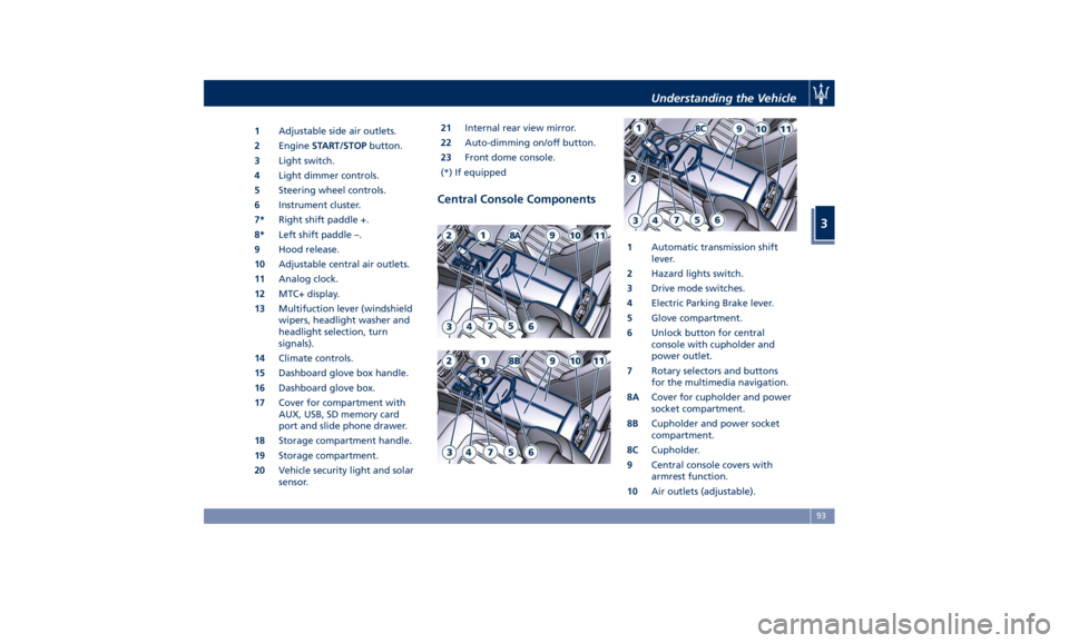
1 Adjustable side air outlets.
2 Engine START/STOP button.
3 Light switch.
4 Light dimmer controls.
5 Steering wheel controls.
6 Instrument cluster.
7* Right shift paddle +.
8* Left shift paddle –.
9 Hood release.
10 Adjustable central air outlets.
11 Analog clock.
12 MTC+ display.
13 Multifuction lever (windshield
wipers, headlight washer and
headlight selection, turn
signals).
14 Climate controls.
15 Dashboard glove box handle.
16 Dashboard glove box.
17 Cover for compartment with
AUX, USB, SD memory card
port and slide phone drawer.
18 Storage compartment handle.
19 Storage compartment.
20 Vehicle security light and solar
sensor. 21 Internal rear view mirror.
22 Auto-dimming on/off button.
23 Front dome console.
(*) If equipped
Central Console Components 1 Automatic transmission shift
lever.
2 Hazard lights switch.
3 Drive mode switches.
4 Electric Parking Brake lever.
5 Glove compartment.
6 Unlock button for central
console with cupholder and
power outlet.
7 Rotary selectors and buttons
for the multimedia navigation.
8A Cover for cupholder and power
socket compartment.
8B Cupholder and power socket
compartment.
8C Cupholder.
9 Central console covers with
armrest function.
10 Air outlets (adjustable).Understanding the Vehicle
3
93
Page 98 of 384
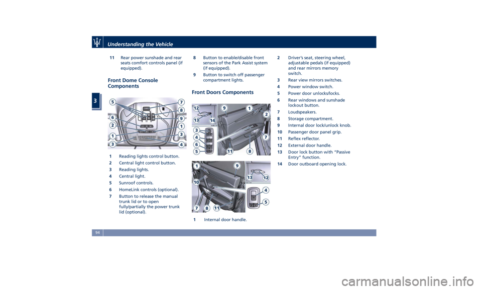
11 Rear power sunshade and rear
seats comfort controls panel (if
equipped).
Front Dome Console
Components
1 Reading lights control button.
2 Central light control button.
3 Reading lights.
4 Central light.
5 Sunroof controls.
6 HomeLink controls (optional).
7 Button to release the manual
trunk lid or to open
fully/partially the power trunk
lid (optional). 8 Button to enable/disable front
sensors of the Park Assist system
(if equipped).
9 Button to switch off passenger
compartment lights.
Front Doors Components
1 Internal door handle. 2 Driver’s seat, steering wheel,
adjustable pedals (if equipped)
and rear mirrors memory
switch.
3 Rear view mirrors switches.
4 Power window switch.
5 Power door unlocks/locks.
6 Rear windows and sunshade
lockout button.
7 Loudspeakers.
8 Storage compartment.
9 Internal door lock/unlock knob.
10 Passenger door panel grip.
11 Reflex reflector.
12 External door handle.
13 Door lock button with “Passive
Entry” function.
14 Door outboard opening lock.Understanding the Vehicle
3
94
Page 103 of 384
Driver Memory Seat This feature allows the driver to store
up to two different memory profiles
for easy recall through a memory
switch. Each memory profile contains
desired position settings for the driver
seat, external side mirrors, adjustable
pedals (optional), and power tilt and
telescopic steering column and a set of
programmed radio stations.
Your key fob RKE transmitter can also
be set to recall the same positions by
pressing the
button.
NOTE:
• Only one key fob RKE transmitter
can be linked to each of the memory
positions.
• “Passive Entry” door handles cannot
be linked to the memory function.
Use either the memory recall switch
or the key fob RKE transmitter (if
linked to the memory feature) to
recall memory positions 1 or 2.
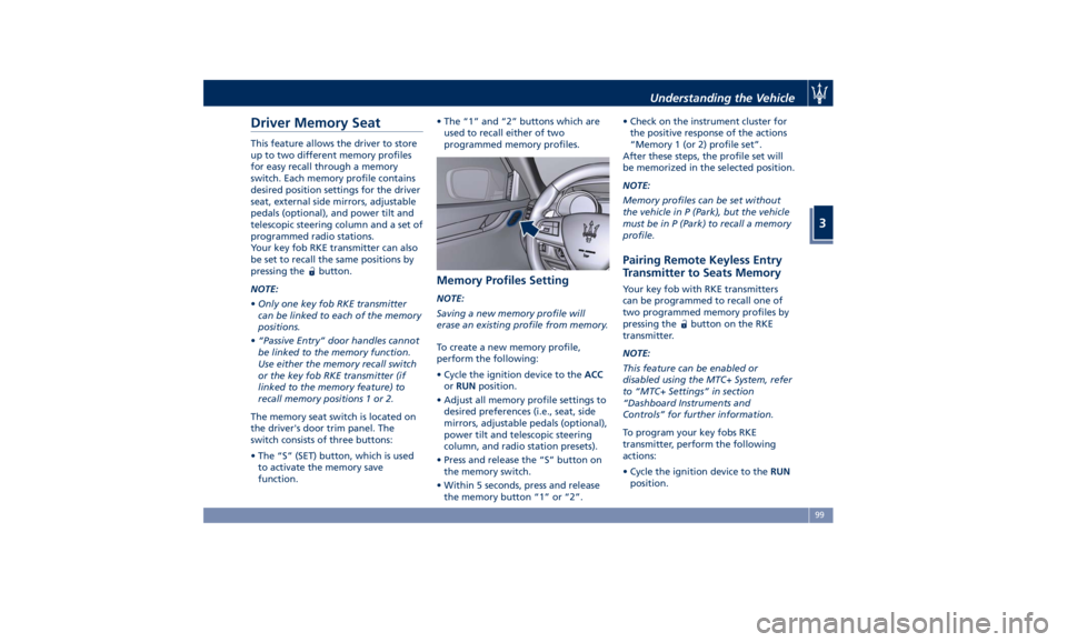
The memory seat switch is located on
the driver's door trim panel. The
switch consists of three buttons:
• The “S” (SET) button, which is used
to activate the memory save
function. • The “1” and “2” buttons which are
used to recall either of two
programmed memory profiles.
Memory Profiles Setting NOTE:
Saving a new memory profile will
erase an existing profile from memory.
To create a new memory profile,
perform the following:
• Cycle the ignition device to the ACC
or RUN position.
• Adjust all memory profile settings to
desired preferences (i.e., seat, side
mirrors, adjustable pedals (optional),
power tilt and telescopic steering
column, and radio station presets).
• Press and release the “S” button on
the memory switch.
• Within 5 seconds, press and release
the memory button “1” or “2”. • Check on the instrument cluster for
the positive response of the actions
“Memory 1 (or 2) profile set”.
After these steps, the profile set will
be memorized in the selected position.
NOTE:
Memory profiles can be set without
the vehicle in P (Park), but the vehicle
must be in P (Park) to recall a memory
profile.
Pairing Remote Keyless Entry
Transmitter to Seats Memory Your key fob with RKE transmitters
can be programmed to recall one of
two programmed memory profiles by
pressing the
button on the RKE
transmitter.
NOTE:
This feature can be enabled or
disabled using the MTC+ System, refer
to “MTC+ Settings” in section
“Dashboard Instruments and
Controls” for further information.
To program your key fobs RKE
transmitter, perform the following
actions:
• Cycle the ignition device to the RUN
position.Understanding the Vehicle
3
99
Page 104 of 384
• Move the seat and/or the other
adjustable devices in the position
that you wish to memorize, or recall
a previously memorized profile,
pressing the corresponding memory
button “1” or “2”.
• Cycle the ignition device to the OFF
position.
• Press and release the “S” button.
• Within 5 seconds, press and release
the memory button “1” or “2”.
• Press and release the
button on
key fob RKE transmitter.
• Within 3 seconds, press and release
the
button on the key fob RKE
transmitter.
To check if the system has memorized
the correct profile, you can move the
seat and press the
button: the seat
will move to the memorized position.
NOTE:
Your key fobs RKE transmitter can be
unlinked to your memory settings by
pressing the “S” button followed by
the
button on the key fob RKE
transmitter. Memory Position Recall NOTE:
The vehicle must be in P (Park) to recall
memory positions. If a recall is
attempted when the vehicle is not in P
(Park), a message will display in the
instrument cluster.
To recall the memory settings for
driver, press memory button number
“1” or “2” on the driver's door trim
panel or the
button on the RKE
transmitter linked to memory position
“1” or “2” with ignition device in the
RUN position.
A recall can be canceled by pressing
any of the buttons (“S”, “1”, or “2”)
during a recall. When a recall is
canceled, the driver seat, external side
mirrors, adjustable pedals (optional),
and power tilt and telescopic steering
column stop moving.
A delay of at least one second will
occur before selecting a new recall. Easy Entry/Exit Driver Seat This feature provides automatic driver
seat positioning to enhance driver
mobility when entering and exiting
the vehicle.
The distance the driver seat moves
depends on where you have the driver
seat positioned when you place the
ignition device to the OFF position.
• When you cycle the ignition device
to the OFF position the driver seat:
• will move about 2.36 in (60 mm)
rearward if the driver seat position
is greater than or equal to ca. 5.51
in (140 mm) forward of the rear
stop;
• will move to a position of ca. 3.15
in (80 mm) rearward of the rear
stop if the driver seat position is
between 5.51 in (140 mm) and 3.15
in (80 mm) forward of the rear
stop.
• The seat will return to its previously
set position when you place the
ignition device into the ACC or RUN
position.
• The Easy Entry/Exit feature is
disabled when the driver seat
position is less than 3.15 in (80 mm)
forward of the rear stop. In this
position, there would be no benefitUnderstanding the Vehicle
3
100
Page 109 of 384
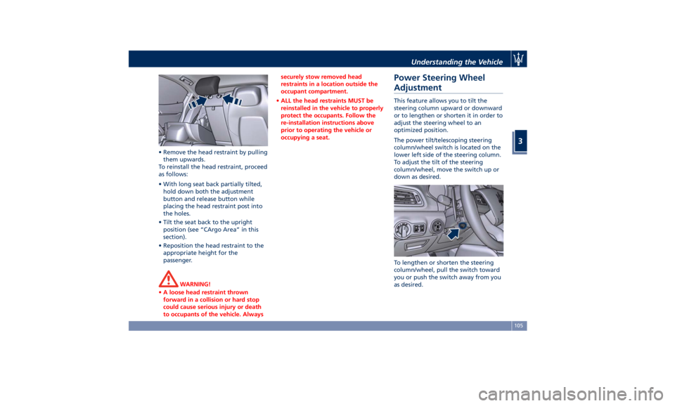
• Remove the head restraint by pulling
them upwards.
To reinstall the head restraint, proceed
as follows:
• With long seat back partially tilted,
hold down both the adjustment
button and release button while
placing the head restraint post into
the holes.
• Tilt the seat back to the upright
position (see “CArgo Area” in this
section).
• Reposition the head restraint to the
appropriate height for the
passenger.
WARNING!
• A loose head restraint thrown
forward in a collision or hard stop
could cause serious injury or death
to occupants of the vehicle. Always securely stow removed head
restraints in a location outside the
occupant compartment.
• ALL the head restraints MUST be
reinstalled in the vehicle to properly
protect the occupants. Follow the
re-installation instructions above
prior to operating the vehicle or
occupying a seat.
Power Steering Wheel
Adjustment This feature allows you to tilt the
steering column upward or downward
or to lengthen or shorten it in order to
adjust the steering wheel to an
optimized position.
The power tilt/telescoping steering
column/wheel switch is located on the
lower left side of the steering column.
To adjust the tilt of the steering
column/wheel, move the switch up or
down as desired.
To lengthen or shorten the steering
column/wheel, pull the switch toward
you or push the switch away from you
as desired.Understanding the Vehicle
3
105
Page 169 of 384
If the warning light stays or turns on
while driving, the engine oil pressure
is too low. The warning light is
combined with a displayed message
and an acoustic signal that will last 4
minutes. In this case, turn the engine
off immediately and carry out the
necessary checks.
Do not operate the vehicle until the
problem has been corrected. This light
does not indicate the oil level. The
engine oil level must be checked with
the dipstick located under the hood
(see “Maintenance Procedures” in
section “Maintenance and Care”).
If the problem persists, contact an
Authorized Maserati Dealer .
Engine Oil Temperature Warning Light
This light indicates that the
engine oil is overheated. The
warning light is combined
with the related displayed
message. In this case, drive carefully
until the temperature drops back to
normal level and the light warning
light turns off.
If the problem persists, contact an
Authorized Maserati Dealer .
Low Engine Oil Level Warning Light
This warning light and the
related displayed message,
indicate a low engine oil level. The engine oil level must be checked
with the dipstick fitted under the
hood (see “Maintenance Procedures”
in section “Maintenance and Care”).
Electric Power Steering Failure
Warning Light
This warning light, and the
related message, illuminate
when the electric power
steering is not operating and
needs service.
If the warning light is on, steering
assistance may be not available.
WARNING!
After battery disconnection event, the
warning light may be on. In this case,
start the engine and perform a
steering wheel stroke end to end.
If the problem persists, contact an
Authorized
Maserati Dealer .
Catalyst Over Temperature Warning
Light
This warning light, and the
related message, light up if
the engine runs irregularly
with consequent high
temperature in the exhaust system. WARNING!
• If the warning light is accompanied
by the message “Catalyst Temp
Getting Hot Reduce Speed”: the
temperature of the catalytic
converters is too high. The driver
must slow down immediately until
the warning light turns off.
• If the message “Catalyst Temp Hot
Stop Safely Wait To Cool” appears
after decelerating: the temperature
in the catalytic converters has
reached a dangerous level and the
catalytic converters could be
damaged. Drive slowly to the
nearest Authorized Maserati Dealer.
• Maserati declines all responsibility
for whatever damage deriving from
non-compliance with the above
mentioned warnings.
Door Ajar Indicator
This
indicator illuminates
when
one or more doors are
ajar. The indicator will show
which door is ajar. When one
or more doors are open, a related
message will be displayed if the
vehicle is running at a speed of 5 mph
(8 km/h) or faster.Dashboard Instruments and Controls
4
165