turn signal MASERATI GRANTURISMO 2019 Owners Manual
[x] Cancel search | Manufacturer: MASERATI, Model Year: 2019, Model line: GRANTURISMO, Model: MASERATI GRANTURISMO 2019Pages: 286, PDF Size: 8.08 MB
Page 28 of 286
Immobilizer System The Maserati CODE System In order to increase protection against
theft, the vehicle is equipped with an
electronic engine immobilizer system
(Maserati CODE), which is
automatically activated when the key
is removed from the ignition switch.
Each starter key contains an electronic
device which transmits a code signal to
the Maserati CODE control unit, and
engine ignition is enabled only if the
key code is recognized by the system.
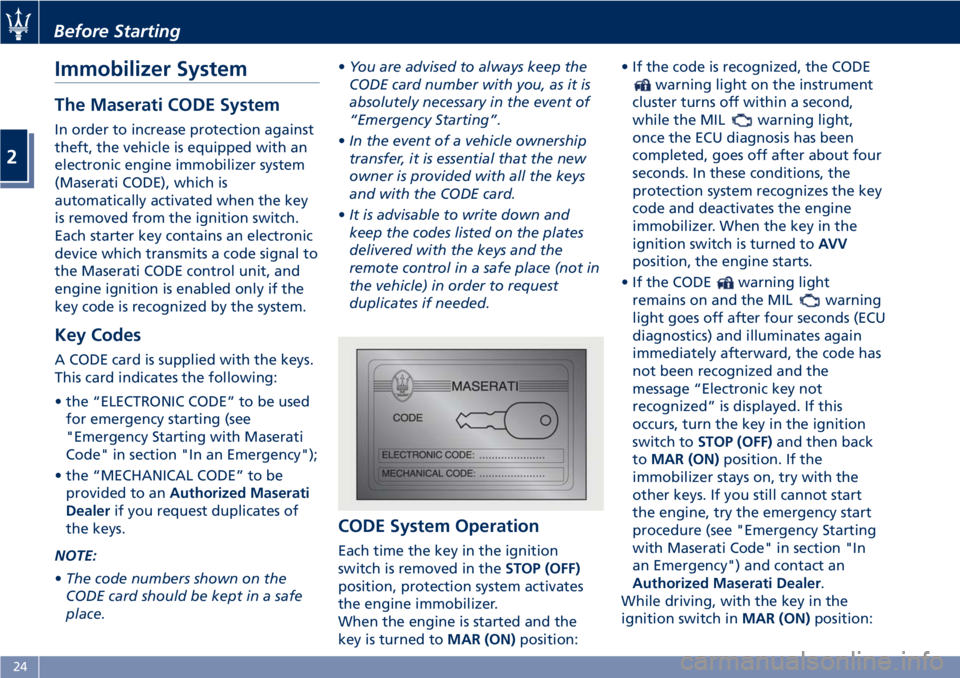
Key Codes A CODE card is supplied with the keys.
This card indicates the following:
• the “ELECTRONIC CODE” to be used
for emergency starting (see
"Emergency Starting with Maserati
Code" in section "In an Emergency");
• the “MECHANICAL CODE” to be
provided to an Authorized Maserati
Dealer if you request duplicates of
the keys.
NOTE:
• The code numbers shown on the
CODE card should be kept in a safe
place. • You are advised to always keep the
CODE card number with you, as it is
absolutely necessary in the event of
“Emergency Starting”.
• In the event of a vehicle ownership
transfer, it is essential that the new
owner is provided with all the keys
and with the CODE card.
• It is advisable to write down and
keep the codes listed on the plates
delivered with the keys and the
remote control in a safe place (not in
the vehicle) in order to request
duplicates if needed.
CODE System Operation Each time the key in the ignition
switch is removed in the STOP (OFF)
position, protection system activates
the engine immobilizer.
When the engine is started and the
key is turned to MAR (ON) position: • If the code is recognized, the CODE
warning light on the instrument
cluster turns off within a second,
while the MIL
warning light,
once the ECU diagnosis has been
completed, goes off after about four
seconds. In these conditions, the
protection system recognizes the key
code and deactivates the engine
immobilizer. When the key in the
ignition switch is turned to AVV
position, the engine starts.
• If the CODE
warning light
remains on and the MIL
warning
light goes off after four seconds (ECU
diagnostics) and illuminates again
immediately afterward, the code has
not been recognized and the
message “Electronic key not
recognized” is displayed. If this
occurs, turn the key in the ignition
switch to STOP (OFF) and then back
to MAR (ON) position. If the
immobilizer stays on, try with the
other keys. If you still cannot start
the engine, try the emergency start
procedure (see "Emergency Starting
with Maserati Code" in section "In
an Emergency") and contact an
Authorized Maserati Dealer .
While driving, with the key in the
ignition switch in MAR (ON) position:Before Starting
2
24
Page 30 of 286
Vehicle Security Alarm The vehicle security alarm system
performs the following functions:
• remote control of the centralized
door locking/unlocking system;
• perimeter surveillance, detecting the
opening of doors, engine/trunk
compartment lids;
• motion surveillance, detecting
intrusion in the passenger
compartment;
• vehicle movement surveillance.
NOTE:
The engine immobilizer operation is
guaranteed by the Maserati CODE
system, which is automatically
activated when the key is removed
from the ignition switch.
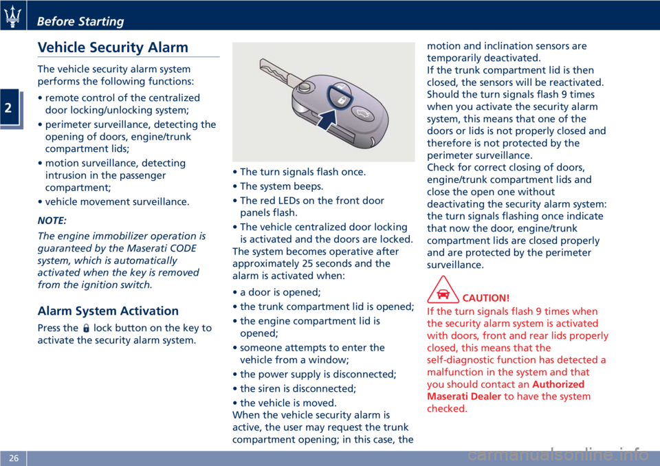
Alarm System Activation Press the lock button on the key to
activate the security alarm system. • The turn signals flash once.
• The system beeps.
• The red LEDs on the front door
panels flash.
• The vehicle centralized door locking
is activated and the doors are locked.
The system becomes operative after
approximately 25 seconds and the
alarm is activated when:
• a door is opened;
• the trunk compartment lid is opened;
• the engine compartment lid is
opened;
• someone attempts to enter the
vehicle from a window;
• the power supply is disconnected;
• the siren is disconnected;
• the vehicle is moved.
When the vehicle security alarm is
active, the user may request the trunk
compartment opening; in this case, the motion and inclination sensors are
temporarily deactivated.
If the trunk compartment lid is then
closed, the sensors will be reactivated.
Should the turn signals flash 9 times
when you activate the security alarm
system, this means that one of the
doors or lids is not properly closed and
therefore is not protected by the
perimeter surveillance.
Check for correct closing of doors,
engine/trunk compartment lids and
close the open one without
deactivating the security alarm system:
the turn signals flashing once indicate
that now the door, engine/trunk
compartment lids are closed properly
and are protected by the perimeter
surveillance.
CAUTION!
If the turn signals flash 9 times when
the security alarm system is activated
with doors, front and rear lids properly
closed, this means that the
self-diagnostic function has detected a
malfunction in the system and that
you should contact an Authorized
Maserati Dealer to have the system
checked.Before Starting
2
26
Page 31 of 286
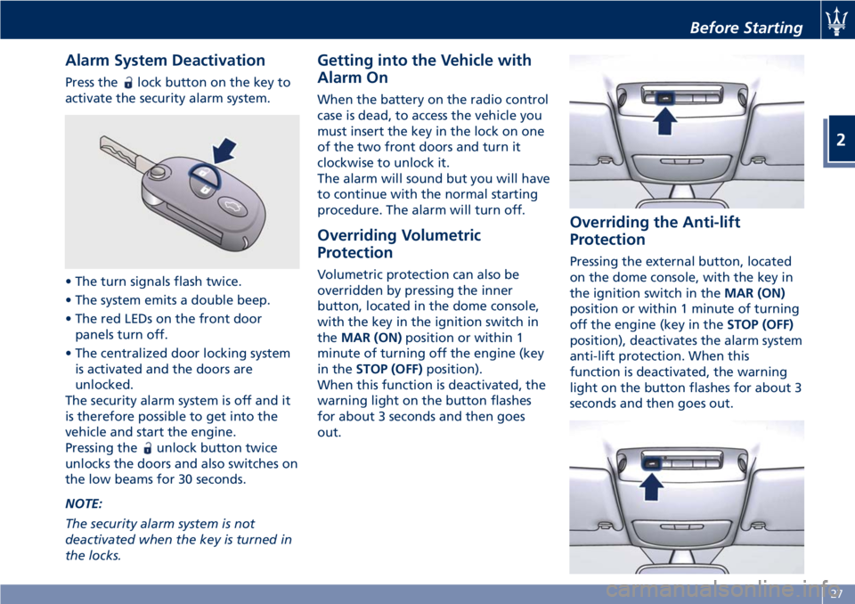
Alarm System Deactivation Press the lock button on the key to
activate the security alarm system.
• The turn signals flash twice.
• The system emits a double beep.
• The red LEDs on the front door
panels turn off.
• The centralized door locking system
is activated and the doors are
unlocked.
The security alarm system is off and it
is therefore possible to get into the
vehicle and start the engine.
Pressing the
unlock button twice
unlocks the doors and also switches on
the low beams for 30 seconds.
NOTE:
The security alarm system is not
deactivated when the key is turned in
the locks. Getting into the Vehicle with
Alarm On When the battery on the radio control
case is dead, to access the vehicle you
must insert the key in the lock on one
of the two front doors and turn it
clockwise to unlock it.
The alarm will sound but you will have
to continue with the normal starting
procedure. The alarm will turn off.
Overriding Volumetric
Protection Volumetric protection can also be
overridden by pressing the inner
button, located in the dome console,
with the key in the ignition switch in
the MAR (ON) position or within 1
minute of turning off the engine (key
in the STOP (OFF) position).
When this function is deactivated, the
warning light on the button flashes
for about 3 seconds and then goes
out. Overriding the Anti-lift
Protection Pressing the external button, located
on the dome console, with the key in
the ignition switch in the MAR (ON)
position or within 1 minute of turning
off the engine (key in the STOP (OFF)
position), deactivates the alarm system
anti-lift protection. When this
function is deactivated, the warning
light on the button flashes for about 3
seconds and then goes out.Before Starting
2
27
Page 36 of 286
Control Plus (MTC+) settings (see
"MTC+ Settings" in section
"Dashboard Instrument and
Controls").
If one or more doors are not properly
closed when locking the doors from
the outside, they will not be locked,
while if the trunk compartment is not
properly closed, the doors will in any
case be locked.
In both cases, the malfunction will be
indicated by the turn signals flashing
for a few seconds.
NOTE:
• The interior door locking/unlocking,
trunk compartment lid opening and
fuel tank door opening buttons are
disabled when the doors are locked
from the outside.
• In the event that the inertia switch
activates, the doors are electrically
unlocked and the vehicle can be
accessed by pressing the rear button
inside each handle.
Opening from the Inside To open the door, even if the lock is
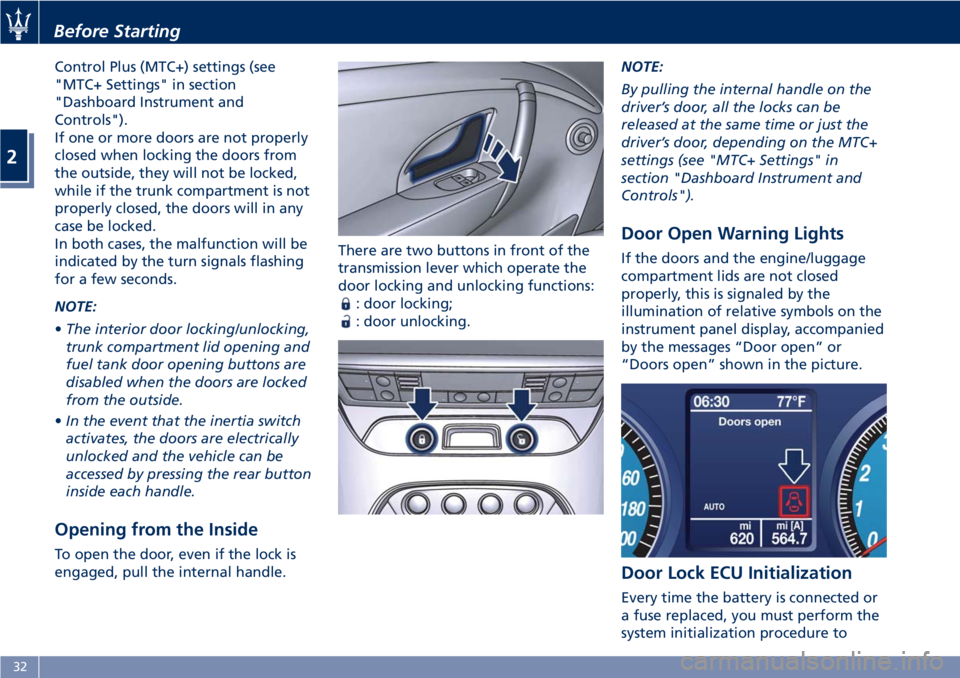
engaged, pull the internal handle. There are two buttons in front of the
transmission lever which operate the
door locking and unlocking functions:
: door locking;
: door unlocking. NOTE:
By pulling the internal handle on the
driver’s door, all the locks can be
released at the same time or just the
driver’s door, depending on the MTC+
settings (see "MTC+ Settings" in
section "Dashboard Instrument and
Controls").
Door Open Warning Lights If the doors and the engine/luggage
compartment lids are not closed
properly, this is signaled by the
illumination of relative symbols on the
instrument panel display, accompanied
by the messages “Door open” or
“Doors open” shown in the picture.
Door Lock ECU Initialization
Every time the battery is connected or
a fuse replaced, you must perform the
system initialization procedure toBefore Starting
2
32
Page 55 of 286
In the event of a side impact, the
Occupant Restraint Controller (ORC)
processes the signals coming from side
sensors and activates air bag
deployment when necessary.
The air bag deploys almost
instantaneously, placing itself between
the occupants and the side of the
vehicle. The air bag deflates
immediately afterward.
In the case of low-severity side
collisions (for which the restraining
action of the seat belts provides
adequate protection), the air bags do
not deploy.
The side air bags are not a substitute
of the seat belts but rather act in
combination with them. As a
consequence, the seat belts must
always be worn as provided for by
applicable legislation in Europe and in
most non-European countries.
WARNING!
• If the
warning light comes on
while driving (fault signal), stop the
vehicle and contact an Authorized
Maserati Dealer to have the system
checked.
• In the event of a collision with
consequent air bag deployment, contact an Authorized Maserati
Dealer for replacement of the entire
safety system, Occupant Restraint
Controller (ORC), seat belts,
pretensioners, and to have the
vehicle electrical system checked.
• Any and all inspections, repairs and
replacements regarding the air bag
must be performed by an
Authorized Maserati Dealer.
NOTE:
• T
o scrap the vehicle, please contact
an Authorized Maserati Dealer in
order to have the air bag system
deactivated.
• If the vehicle is sold, the new owners
must read the above described
instructions for use and warnings on
this “Owner’s Manual” that is an
integral part of the car.
Occupant Restraint Controller
(ORC) The Occupant Restraint Controller
(ORC) determines if deployment of the
front air bags and/or side air bags in a
frontal or side collision is required.
Based on the impact sensor's signals,
the central electronic ORC deploys the
front air bags, the side air bags and seat belt pretensioners, as required,
depending on the severity and type of
impact.
The ORC monitors the readiness of the
electronic parts of the air bag system
whenever the key in the ignition
switch is in the MAR (ON) position. If
the key is in the STOP (OFF) position,
in the ACC position, or not active, the
air bag system is not activated and the
air bags will not inflate.
The ORC contains a backup power
supply system that may deploy the air
bags even if the battery has low
power or it becomes disconnected
prior to deployment. When starting
the vehicle, ORC turns on the
air
bag warning light on the instrument
cluster for approximately 4 to 8
seconds for a test.
After the test, the
air bag warning
light will turn off. If the ORC, during
the diagnosis phase detects a
malfunction that could affect the air
bag system, it turns on the
air bag
warning light and the “Airbag failure
go to dealer” message either
momentarily or continuously. The
diagnostics also record the nature of
the malfunction. A beep will sound if
the
air bag warning light
illuminates again after initial startup.Before Starting
2
51
Page 65 of 286
Always stop when the acoustic
signal becomes steady.
Stop & Go Feature This function is enabled by the
manufacturer and it can be disabled
by the MTC+ (see chapter "MTC+
Settings" in section "Dashboard
Instruments and Controls"), select and
tick the “Stop & Go Parking Sensors”
feature.
When vehicle speed is equal to or
lower than 6 mph (10 km/h), this
function helps the driver under special
traffic conditions as it signals that the
vehicle before you is at a min.
distance.
System with Enabled Stop &
Go Feature When the "Stop & Go" feature is
enabled through the MTC+, all sensors
are automatically enabled with the
key in the ignition switch turned to
MAR (ON) position, but they are not
displayed on the instrument cluster.
When the R (Reverse) gear is engaged
or an obstacle is detected, the
corresponding detection areas are
displayed on the instrument cluster. As
soon as the R (Reverse) gear is
disengaged, all sensors are still active: the rear ones for approx. 10 seconds
or until a speed of approx. 6 mph
(10 km/h) is exceeded, and the front
ones until a speed of approx. 6 mph
(10 km/h) is exceeded. When driving at
a speed equal to or lower than 6 mph
(10 km/h), as soon as the system
detects an obstacle, the front sensor
detection areas are displayed, and the
acoustic signals start to be emitted. If
no obstacle is detected for 10 seconds,
the displayed information disappears.
Front sensors can be temporarily
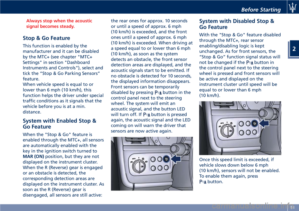
disabled by pressing
button in the
control panel next to the steering
wheel. The system will emit an
acoustic signal, and the button LED
will turn off. If
button is pressed
again, the acoustic signal and the LED
coming on will warn the driver that
sensors are now active again. System with Disabled Stop &
Go Feature With the "Stop & Go" feature disabled
through the MTC+, rear sensor
enabling/disabling logic is kept
unchanged. As for front sensors, the
“Stop & Go” function signal status will
not be changed if the
button in
the control panel next to the steering
wheel is pressed and front sensors will
be active and displayed on the
instrument cluster until speed will be
equal to or lower than 6 mph
(10 km/h).
Once this speed limit is exceeded, if
vehicle slows down below 6 mph
(10 km/h), sensors will not be enabled.
To enable them again, press
button.Before Starting
2
61
Page 66 of 286
NOTE:
Front sensors are enabled only when
button LED is illuminated. In
addition, any pressing of
button
when vehicle speed is above 6 mph
(10 km/h) will be ignored by the
system.
Obstacle Signalling The acoustic signals are emitted by
two buzzers, one under the dashboard
and one in proximity of the luggage
shelf.
When the obstacle is located at a
distance of less than 14 in (35 cm) from
the bumper, the beep is continuous.
The warning beep stops immediately if
the distance between the vehicle and
the obstacle increases. The tone cycle is
constant if the distance measured by
the central sensors remains unaltered.
If this occurs with the lateral sensors,
the signal stops after approximately 7
seconds, to prevent for example
continuous beeps in the event of
maneuvers alongside walls.
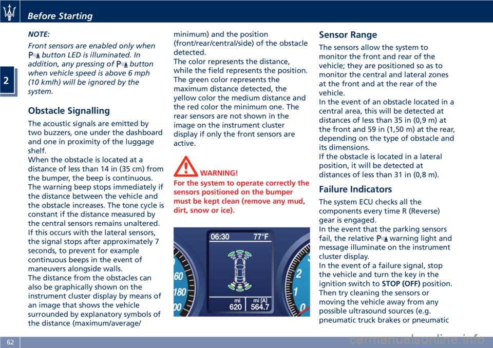
The distance from the obstacles can
also be graphically shown on the
instrument cluster display by means of
an image that shows the vehicle
surrounded by explanatory symbols of
the distance (maximum/average/ minimum) and the position
(front/rear/central/side) of the obstacle
detected.
The color represents the distance,
while the field represents the position.
The green color represents the
maximum distance detected, the
yellow color the medium distance and
the red color the minimum one. The
rear sensors are not shown in the
image on the instrument cluster
display if only the front sensors are
active.
WARNING!
For the system to operate correctly the
sensors positioned on the bumper
must be kept clean (remove any mud,
dirt, snow or ice). Sensor Range The sensors allow the system to
monitor the front and rear of the
vehicle; they are positioned so as to
monitor the central and lateral zones
at the front and at the rear of the
vehicle.
In the event of an obstacle located in a
central area, this will be detected at
distances of less than 35 in (0,9 m) at
the front and 59 in (1,50 m) at the rear,
depending on the type of obstacle and
its dimensions.
If the obstacle is located in a lateral
position, it will be detected at
distances of less than 31 in (0,8 m).
Failure Indicators The system ECU checks all the
components every time R (Reverse)
gear is engaged.
In the event that the parking sensors
fail, the relative
warning light and
message illuminate on the instrument
cluster display.
In the event of a failure signal, stop
the vehicle and turn the key in the
ignition switch to STOP (OFF) position.
Then try cleaning the sensors or
moving the vehicle away from any
possible ultrasound sources (e.g.
pneumatic truck brakes or pneumaticBefore Starting
2
62
Page 71 of 286
• Never place or install floor mats or
other floor coverings in the vehicle
that cannot be properly secured to
prevent them from moving and
interfering with the pedals.
• Never put floor mats or other floor
coverings on top of already installed
floor mats. Additional floor mats
and other coverings will reduce the
size of the pedal area and interfere
with the pedals.
• Check mounting of mats on a
regular basis. Always properly
reinstall and secure floor mats that
have been removed for cleaning.
• Always make sure that objects
cannot fall into the driver footwell
while the vehicle is moving. Objects
can become trapped under the
brake pedal and accelerator pedal
causing a loss of vehicle control.
• Mounting posts must be properly
installed, if not equipped from the
factory. Failure to properly follow
floor mat installation or mounting
can cause interference with the
brake pedal and accelerator pedal
operation causing loss of control of
the vehicle. Tires
•
Examine tires for excessive tread
wear and uneven wear patterns.
• Check for stones, nails, glass, or
other objects lodged in the tread or
sidewall.
• Inspect the tread for cuts and cracks.
• Inspect sidewalls for cuts, cracks and
bulges.
• Check the wheel nuts for tightness.
• Check the tires (see “Tire Inflation
Pressure” chapter in section
“Features and Specifications”) for
proper cold inflation pressure.
Lights and Indicator Lights
• Have someone observe the
operation of exterior lights while
you operate the controls (see
“Lights” chapter in section
“Understanding the Vehicle”).
• Check turn signal and high beam
indicator lights on the instrument
cluster (see “Instrument Cluster”
chapter in section “Dashboard
Instruments and Controls”).
Door Latches
• Check for positive closing, latching,
and locking of doors and trunk lid
(see chapter “Doors” and “Open and
Close the Trunk Lid” in this section). Fluid Leaks
• Check area under vehicle after
overnight parking for recent fluid
leaks (oil, fuel, etc.).
• If gasoline fumes are detected or
fluid leaks are suspected, contact an
Authorized Maserati Dealer .
WARNING!
California Proposition 65
Operating, servicing and maintaining
a passenger vehicle or off-road vehicle
can expose you to chemicals including
such as, engine exhaust, carbon
monoxide, phthalates and lead, that
which are know to the State of
California to cause cancer and birth
defects or other reproductive harm. To
minimize exposure, avoid breathing
exhaust, do not idle the engine except
as necessary, service your vehicle in a
well-ventilated area and wear gloves
or wash your hands frequently when
servicing your vehicle. For more
information go to:
www.P65Warnings.ca.gov/passenger-
vehicleBefore Starting
2
67
Page 75 of 286
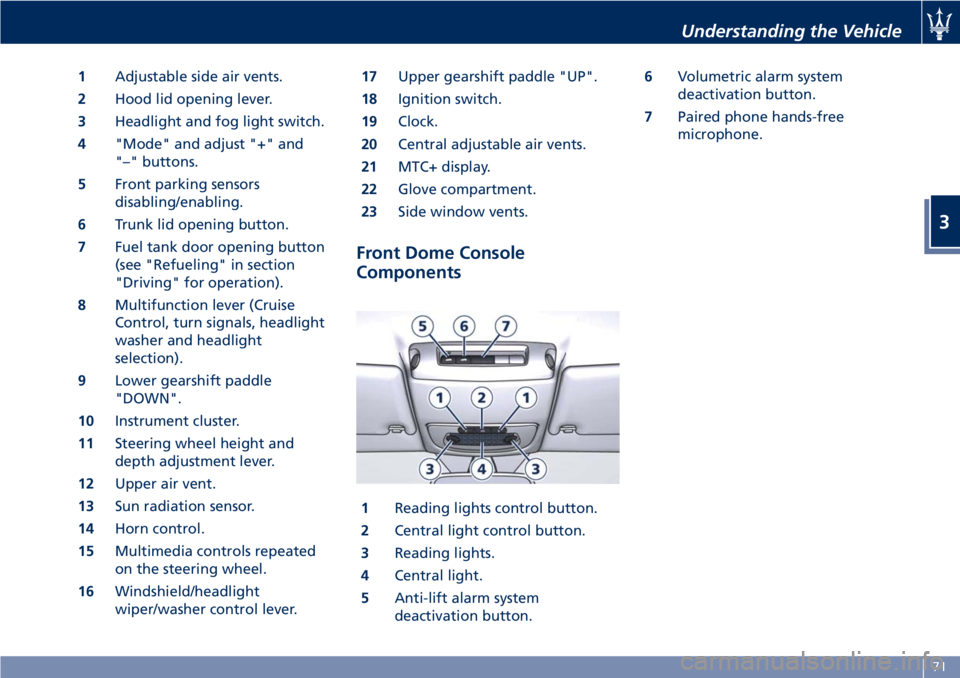
1 Adjustable side air vents.
2 Hood lid opening lever.
3 Headlight and fog light switch.
4 "Mode" and adjust "+" and
"–" buttons.
5 Front parking sensors
disabling/enabling.
6 Trunk lid opening button.
7 Fuel tank door opening button
(see "Refueling" in section
"Driving" for operation).
8 Multifunction lever (Cruise
Control, turn signals, headlight
washer and headlight
selection).
9 Lower gearshift paddle
"DOWN".
10 Instrument cluster.
11 Steering wheel height and
depth adjustment lever.
12 Upper air vent.
13 Sun radiation sensor.
14 Horn control.
15 Multimedia controls repeated
on the steering wheel.
16 Windshield/headlight
wiper/washer control lever. 17 Upper gearshift paddle "UP".
18 Ignition switch.
19 Clock.
20 Central adjustable air vents.
21 MTC+ display.
22 Glove compartment.
23 Side window vents.
Front Dome Console
Components
1 Reading lights control button.
2 Central light control button.
3 Reading lights.
4 Central light.
5 Anti-lift alarm system
deactivation button. 6 Volumetric alarm system
deactivation button.
7 Paired phone hands-free
microphone.
Understanding the Vehicle
3
71
Page 87 of 286
Lights The external lights and turn signals
turn on only with the key in the
ignition switch in MAR (ON) position.
Only the parking lights can be turned
on at any time.
The external lights can be turned on
and off manually or automatically,
according to the brightness of the
light outside.
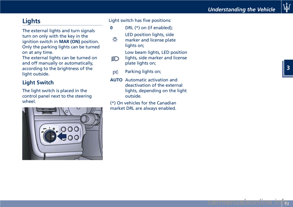
Light Switch The light switch is placed in the
control panel next to the steering
wheel. Light switch has five positions:
0 DRL (*) on (if enabled);
LED position lights, side
marker and license plate
lights on;
Low beam lights, LED position
lights, side marker and license
plate lights on;
Parking lights on;
AUTO Automatic activation and
deactivation of the external
lights, depending on the light
outside.
(*) On vehicles for the Canadian
market DRL are always enabled. Understanding the Vehicle
3
83