instrument panel MASERATI GRANTURISMO 2020 User Guide
[x] Cancel search | Manufacturer: MASERATI, Model Year: 2020, Model line: GRANTURISMO, Model: MASERATI GRANTURISMO 2020Pages: 286, PDF Size: 6.7 MB
Page 196 of 286
Refueling
Fuel Filler Neck Access
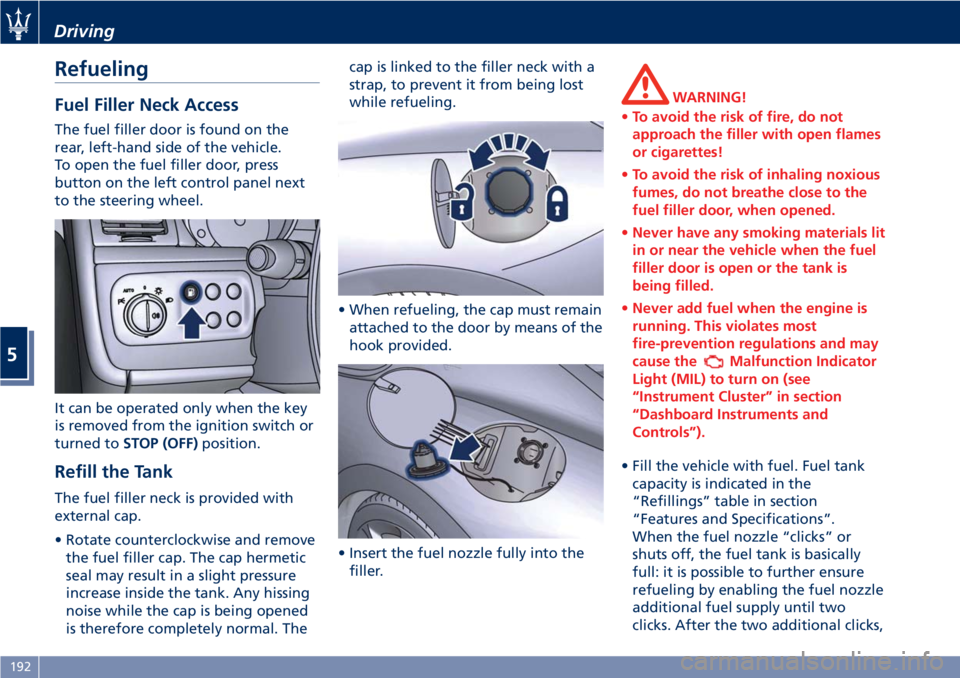
The fuel filler door is found on the
rear, left-hand side of the vehicle.
To open the fuel filler door, press
button on the left control panel next
to the steering wheel.
It can be operated only when the key
is removed from the ignition switch or
turned toSTOP (OFF)position.
Refill the Tank
The fuel filler neck is provided with
external cap.
• Rotate counterclockwise and remove
the fuel filler cap. The cap hermetic
seal may result in a slight pressure
increase inside the tank. Any hissing
noise while the cap is being opened
is therefore completely normal. Thecap is linked to the filler neck with a
strap, to prevent it from being lost
while refueling.
• When refueling, the cap must remain
attached to the door by means of the
hook provided.
• Insert the fuel nozzle fully into the
filler.
WARNING!
•To avoid the risk of fire, do not
approach the filler with open flames
or cigarettes!
•To avoid the risk of inhaling noxious
fumes, do not breathe close to the
fuel filler door, when opened.
•Never have any smoking materials lit
in or near the vehicle when the fuel
filler door is open or the tank is
being filled.
•Never add fuel when the engine is
running. This violates most
fire-prevention regulations and may
cause the
Malfunction Indicator
Light (MIL) to turn on (see
“Instrument Cluster” in section
“Dashboard Instruments and
Controls”).
• Fill the vehicle with fuel. Fuel tank
capacity is indicated in the
“Refillings” table in section
“Features and Specifications”.
When the fuel nozzle “clicks” or
shuts off, the fuel tank is basically
full: it is possible to further ensure
refueling by enabling the fuel nozzle
additional fuel supply until two
clicks. After the two additional clicks,
Driving
5
192
Page 206 of 286
Tool Kit
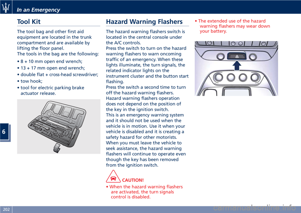
The tool bag and other first aid
equipment are located in the trunk
compartment and are available by
lifting the floor panel.
The tools in the bag are the following:
•8+10mmopen end wrench;
• 13 + 17 mm open end wrench;
• double flat + cross-head screwdriver;
• tow hook;
• tool for electric parking brake
actuator release.
Hazard Warning Flashers
The hazard warning flashers switch is
located in the central console under
the A/C controls.
Press the switch to turn on the hazard
warning flashers to warn oncoming
traffic of an emergency. When these
lights illuminate, the turn signals, the
related indicator lights on the
instrument cluster and the button start
flashing.
Press the switch a second time to turn
off the hazard warning flashers.
Hazard warning flashers operation
does not depend on the position of
the key in the ignition switch.
This is an emergency warning system
and it should not be used when the
vehicle is in motion. Use it when your
vehicle is disabled and it is creating a
safety hazard for other motorists.
When you must leave the vehicle to
seek assistance, the hazard warning
flashers will continue to operate even
though the key has been removed
from the ignition switch.
CAUTION!
• When the hazard warning flashers
are activated, the turn signals
control is disabled.• The extended use of the hazard
warning flashers may wear down
your battery.
In an Emergency
6
202
Page 208 of 286
Engine Overheating
To reduce potentially overheating of
the engine in city traffic, while
stationary, place the transmission in N
(Neutral), but do not increase the
engine idle speed.
NOTE:
There are steps that you can take to
slow down an impending overheat
condition:
•If your air conditioner (A/C) is on,
turn it off. The A/C system adds heat
to the engine cooling system and
turning the A/C off can help remove
this heat.
•You can also turn the temperature
control to maximum heat, the mode
control to floor and the blower
control to high. This allows the
heater core to act as a supplement to
the radiator and aids in removing
heat from the engine cooling system.
CAUTION!
Driving with a hot cooling system
could damage the engine. If the
temperature gauge is positioned on
the red zone (refer to “Instrument
Cluster” in section “DashboardInstruments and Controls”), pull over
and stop the vehicle. Idle the vehicle
with the air conditioner turned off
until the temperature gauge drops
back into the normal range. If the
temperature gauge remains on the red
zone turn the engine off immediately
and contact theAuthorized Maserati
Dealer.
WARNING!
You or others can be badly burned by
hot engine coolant (antifreeze) or
steam from your radiator. If you see or
hear steam coming from under the
hood, do not open it until the radiator
has had time to cool.
Never try to open a coolant bottle
pressure cap (refer to “Maintenance
Procedures” in section “Maintenance
and Care”) when the radiator is
overheated.
In case of a Punctured Tire
The vehicle can be equipped with a
tire repair kit or with a compact spare
wheel.
Using Tire Repair Kit
Small punctures up to 1⁄4” (6 mm) in
the tire tread can be sealed using the
tire repair kit, fitted beneath the floor
panel of the trunk compartment.
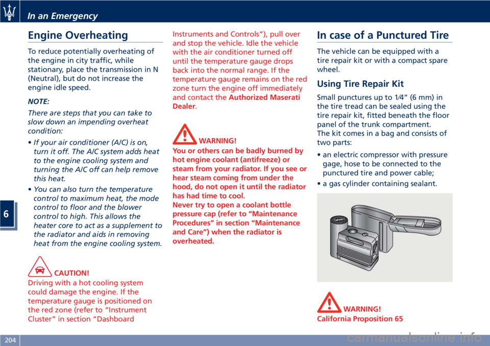
The kit comes in a bag and consists of
two parts:
• an electric compressor with pressure
gage, hose to be connected to the
punctured tire and power cable;
• a gas cylinder containing sealant.
WARNING!
California Proposition 65
In an Emergency
6
204
Page 249 of 286
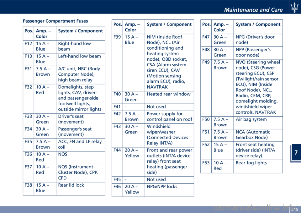
Passenger Compartment Fuses
Pos. Amp. –
ColorSystem / Component
F12 15 A –
BlueRight-hand low
beam
F13 15 A –
BlueLeft-hand low beam
F31 7.5 A –
BrownA/C unit, NBC (Body
Computer Node),
high beam relay
F32 10 A –
RedDomelights, step
lights, CAV, driver-
and passenger-side
footwell lights,
outside mirror lights
F33 30 A –
GreenDriver’s seat
(movement)
F34 30 A –
GreenPassenger’s seat
(movement)
F35 7.5 A –
BrownACC, FN and LF relay
coil
F36 10 A –
RedNQS
F37 10 A –
RedNQS (Instrument
Cluster Node), CPP,
CPD
F38 15 A –
BlueRear lid lock
Pos. Amp. –
ColorSystem / Component
F39 15 A –
BlueNIM (Inside Roof
Node), NCL (Air
conditioning and
heating system
node), OBD socket,
CSA (Alarm system
siren ECU), CAV
(Motion sensing
alarm ECU), radio,
NAVTRAK
F40 30 A –
GreenHeated rear window
F41 - Not used
F42 7.5 A –
BrownPower supply for
control panel on roof
F43 30 A –
GreenWindshield
wiper/washer
(Connected Devices
Relay INT/A)
F44 20 A –
YellowFront and rear power
outlets (INT/A device
relay) front seat
heating (passenger
side)
F45 - Not used
F46 20 A –
YellowNPG/NPP locksPos. Amp. –
ColorSystem / Component
F47 30 A –
GreenNPG (Driver’s door
node)
F48 30 A –
GreenNPP (Passenger’s
door node)
F49 7.5 A –
BrownNVO (Steering wheel
node), CSG (Power
steering ECU), CSP
(Twilight/rain sensor
ECU), NIM (Inside
Roof Node), NCL,
Radio, CEM, CRP,
domelight molding,
windshield wiper
controls, NAVTRAK
F50 7.5 A –
BrownAir bag system
F51 7.5 A –
BrownNCA (Automatic
Gearbox Node)
F52 15 A –
BlueFront seat heating
(driver side) (INT/A
device relay)
F53 10 A –
RedRear fog lights
Maintenance and Care
7
245
Page 261 of 286
External plastic parts must be cleaned
with the same procedure followed for
the normal washing of the bodywork.
Avoid, as far as possible, parking the
vehicle under trees; the resinous
substances that very often drop from
the trees give the paint a dull
appearance and increase the
possibility of originating corrosive
processes.
It is important that the drain holes in
the lower sides of the doors, rocker
panels, and trunk bottom be kept
clear and open.
CAUTION!
• Bird droppings must be washed off
immediately and thoroughly, since
their acidity is particularly corrosive.
• To provide better protection for the
paint, polish the vehicle at intervals
with a suitable product leaving a
protective film on the paint.
• If the vehicle is washed using
high-pressure water jets or cleaners,
it is important that the nozzle of the
jet be kept at a distance of at least
16 in (40 cm) from the bodywork to
avoid damaging it.
• If you are washing the vehicle with
roller brushes, you must protect theedges of the rear, lateral brand
symbol with tape, to prevent it from
being detached by the revolving
brushes.
Glass Surfaces
All glass surfaces should be cleaned on
a regular basis with any commercial
household-type glass cleaner.
Never use an abrasive type cleaner.
Use caution when cleaning the inside
rear window equipped with electric
defrosters. Do not use scrapers or
other sharp instrument that may
scratch the electric elements.
When cleaning the rearview mirror,
spray cleaner on the towel or rag that
you are using. Do not spray cleaner
directly on the mirror.
Labels can be peeled off after soaking
with warm water.
Keep all objects a safe distance from
the window.
Cleaning Headlights
Your vehicle has plastic headlights that
are lighter and less susceptible to
stone breakage than glass headlights.
Plastic is not as scratch resistant as
glass and therefore different lens
cleaning procedures must be followed.
To minimize the possibility of
scratching the lenses and reducinglight output, avoid wiping with a dry
cloth. To remove road dirt, wash with
a mild soap solution followed by
rinsing.
Do not use abrasive cleaning
components, solvents, steel wool or
other aggressive material to clean the
lenses.
Moldings and Aluminum Trims
• For cleaning moldings and aluminum
trims, avoid the use of acidic or
alkaline cleaning agents that can
destroy the protecting surface
treatment.
• After washing aluminum trim with
warm water, apply the cleaning
agent with a clean tissue or a soft
sponge on the surface. Do not use
any other equipment such as
brushes, steel wool, abrasives or any
other equipment for cleaning.
• After cleaning, please rinse the
aluminum trim with a lot of clear
water.
• While cleaning in the car, please
make sure that the moldings and
aluminum trims only get in contact
with soft brushes or textiles.
Engine Compartment
At the end of each winter season,
carefully wash the engine
Maintenance and Care
7
257