tire pressure MASERATI GRANTURISMO 2020 Owners Manual
[x] Cancel search | Manufacturer: MASERATI, Model Year: 2020, Model line: GRANTURISMO, Model: MASERATI GRANTURISMO 2020Pages: 286, PDF Size: 6.7 MB
Page 11 of 286
Abbreviations
Some descriptions and terms with
particular meanings are found in this
manual in abbreviated form.
A/CAir-Conditioning System.
ABSAnti-Lock Braking System.
ALCAdaptive Light Control.
ALRAutomatic Locking Retractor.
ASRAnti-Slip Regulation.
BOSBrake Override System.
CANController Area Network.
CCCruise Control.
CRSChild Restraint System.
DRLDaytime Running Lights.
EBDElectronic Brake-force
Distribution.
ECUElectronic Control Unit.
EDREvent Data Recorder.
EPBElectric Parking Brake.
ESCElectronic Stability Control.
ETDEmergency Tensioning
Device.
FTPFlash To Pass.
HBAHydraulic Brake Assistance.
ICEIncrease Control and
Efficiency.LATCHLower Anchors and Tether
for CHildren.
MILMalfunction Indicator Light.
MTC+Maserati Touch Control Plus.
OBDOn Board Diagnostics.
ORCOccupant Restraint
Controller.
RHDRight-Hand Drive.
SBRSeat Belt Reminder.
TFTThin Film Transistor.
TPMSTire Pressure Monitoring
System.
VINVehicle Identification
Number.
Updating
Constant improvements are being
performed to maintain this vehicle's
high level of quality. Therefore, there
may be differences between this
manual and your vehicle.
Maserati reserves the right to carry
out design and functional changes
and to provide updates or
improvements.
This Owner's Manual illustrates and
describes all versions of the current
vehicle model. Therefore, some of the
equipment and accessories in this
publication may not appear on your
vehicle; please only consider the
information related to your vehicle.
All specifications and illustrations
contained in this manual are as of the
Manual publishing date.
NOTE:
The updated version of the on-board
documentation can be consulted by
accessing the section “SERVICES” on
the websitewww.maserati.comor by
using the specific apps developed for
the more common Tablet and
Smartphone.
Introduction
1
7
Page 71 of 286
•Never place or install floor mats or
other floor coverings in the vehicle
that cannot be properly secured to
prevent them from moving and
interfering with the pedals.
•Never put floor mats or other floor
coverings on top of already installed
floor mats. Additional floor mats
and other coverings will reduce the
size of the pedal area and interfere
with the pedals.
•Check mounting of mats on a
regular basis. Always properly
reinstall and secure floor mats that
have been removed for cleaning.
•Always make sure that objects
cannot fall into the driver footwell
while the vehicle is moving. Objects
can become trapped under the
brake pedal and accelerator pedal
causing a loss of vehicle control.
•Mounting posts must be properly
installed, if not equipped from the
factory. Failure to properly follow
floor mat installation or mounting
can cause interference with the
brake pedal and accelerator pedal
operation causing loss of control of
the vehicle.Tires
• Examine tires for excessive tread
wear and uneven wear patterns.
• Check for stones, nails, glass, or
other objects lodged in the tread or
sidewall.
• Inspect the tread for cuts and cracks.
• Inspect sidewalls for cuts, cracks and
bulges.
• Check the wheel nuts for tightness.
• Check the tires (see “Tire Inflation
Pressure” chapter in section
“Features and Specifications”) for
proper cold inflation pressure.
Lights and Indicator Lights
• Have someone observe the
operation of exterior lights while
you operate the controls (see
“Lights” chapter in section
“Understanding the Vehicle”).
• Check turn signal and high beam
indicator lights on the instrument
cluster (see “Instrument Cluster”
chapter in section “Dashboard
Instruments and Controls”).
Door Latches
• Check for positive closing, latching,
and locking of doors and trunk lid
(see chapter “Doors” and “Open and
Close the Trunk Lid” in this section).Fluid Leaks
• Check area under vehicle after
overnight parking for recent fluid
leaks (oil, fuel, etc.).
• If gasoline fumes are detected or
fluid leaks are suspected, contact an
Authorized Maserati Dealer.
WARNING!
California Proposition 65
Operating, servicing and maintaining
a passenger vehicle or off-road vehicle
can expose you to chemicals including
such as, engine exhaust, carbon
monoxide, phthalates and lead, that
which are know to the State of
California to cause cancer and birth
defects or other reproductive harm. To
minimize exposure, avoid breathing
exhaust, do not idle the engine except
as necessary, service your vehicle in a
well-ventilated area and wear gloves
or wash your hands frequently when
servicing your vehicle. For more
information go to:
www.P65Warnings.ca.gov/passenger-
vehicle
Before Starting
2
67
Page 115 of 286
Left Turn Signal Indicator Light
The indicator lights up when
the left turn signals or the
hazard flashers are turned on.
The indicator light will flash at
the same frequency of the turn signals
and is controlled by the left
multifunction lever.
If the vehicle electronics sense that the
vehicle drives for more than 1 mile
(1.6 km) with either turn signal on, a
continuous sound will alert the driver
to turn the signal off.
If the indicator flashes at a rapid rate,
check for a defective exterior light
bulb.
Rear Fog Light Indicator
This indicator lights up when
the rear fog lights are
switched on.
Tire Pressure Monitoring Light (*)
This indicator light is
connected to the Tire Pressure
Monitoring System (TPMS).
Under normal conditions, the
warning light should illuminate when
the key in the ignition switch is in
MAR (ON)position and should go off
as soon as the engine is started.
If the warning light remains lit or
illuminates while driving, the pressureof one or more tires is too low: the
related message will be displayed.
If the warning light flashes prior to
remain on, it indicates that the system
is temporarily unavailable.
This warning light illuminates even
when you calibrate the TPMS and
remains lit until the system is
calibrated.
Please refer to “Tire Pressure
Monitoring System (TPMS)” in section
“Driving” for further information.
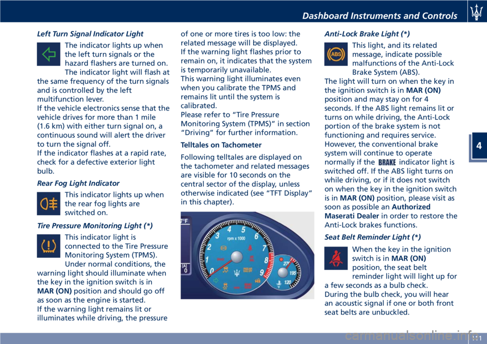
Telltales on Tachometer
Following telltales are displayed on
the tachometer and related messages
are visible for 10 seconds on the
central sector of the display, unless
otherwise indicated (see “TFT Display”
in this chapter).Anti-Lock Brake Light (*)
This light, and its related
message, indicate possible
malfunctions of the Anti-Lock
Brake System (ABS).
The light will turn on when the key in
the ignition switch is inMAR (ON)
position and may stay on for 4
seconds. If the ABS light remains lit or
turns on while driving, the Anti-Lock
portion of the brake system is not
functioning and requires service.
However, the conventional brake
system will continue to operate
normally if the
indicator light is
switched off. If the ABS light turns on
while driving, or if it does not switch
on when the key in the ignition switch
is inMAR (ON)position, please visit as
soon as possible anAuthorized
Maserati Dealerin order to restore the
Anti-Lock brakes functions.
Seat Belt Reminder Light (*)
When the key in the ignition
switch is inMAR (ON)
position, the seat belt
reminder light will light up for
a few seconds as a bulb check.
During the bulb check, you will hear
an acoustic signal if one or both front
seat belts are unbuckled.
Dashboard Instruments and Controls
4
111
Page 118 of 286
TFT Display: Menus and
Settings
The TFT display performs the following
functions:
• provides general information while
driving;
• signals failures and warnings.
The user can interact with the system
by setting the parameters for the
information that can be recalled.
The screen page displayed following
the initial check cycle, in normal
operating conditions, (standard screen
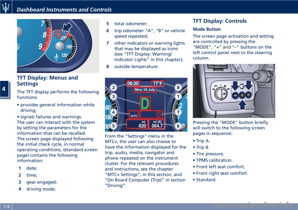
page) contains the following
information:
1date;
2time;
3gear engaged;
4driving mode;5total odometer;
6trip odometer "A", "B" or vehicle
speed repeated;
7other indicators or warning lights
that may be displayed as icons
(see "TFT Display: Warning/
Indicator Lights" in this chapter);
8outside temperature.
From the "Settings" menu in the
MTC+, the user can also choose to
have the information displayed for the
trip, audio, media, navigator and
phone repeated on the instrument
cluster. For the relevant procedures
and instructions, see the chapter
“MTC+ Settings”, in this section, and
“On Board Computer (Trip)” in section
“Driving”.
TFT Display: Controls
Mode Button
The screen page activation and setting
are controlled by pressing the
"MODE", “+” and “–” buttons on the
left control panel next to the steering
column.
Pressing the "MODE" button briefly
will switch to the following screen
pages in sequence:
• Trip A.
• Trip B.
• Tire pressure.
• TPMS calibration.
• Front left seat comfort.
• Front right seat comfort.
• Standard.
Dashboard Instruments and Controls
4
114
Page 119 of 286
“+“ and “–” Buttons
By means of the “+ “ and “–” buttons,
the user can adjust the instrument
cluster brightness.
When a screen page is viewed, these
buttons can be used to select the
available options (see paragraph "TFT
Display: Screen Pages" in this chapter).
TFT Display: Screen Pages
Trip Screen Page
The Trip screen page is recalled by
pressing the “MODE” button. Each
Trip screen page “A” or “B” is timed,
i.e. it is displayed for a maximum of 10
seconds, after which the screen page
previously active is displayed once
again.
Before the 10 second timing has
elapsed, pressing the “MODE” button
briefly (less than 2 seconds) will reset
the trip information relating to the
flashing odometer “A” or “B”.
When the “Trip A” or “Trip B” feature
is active, the following information is
viewed on the display:
• traveled distance (shown in the
lower right area);
• average fuel consumption (Avg.
cons.)
• average traveling speed (Avg.
speed);• trip time;
• fuel range (Range);
The unit for this data can be adjusted
by the user from the MTC+ Settings
menu.
NOTE:
Trip and Service information can be
viewed by accessing the “Trip” menu
on the MTC+ screen (see “On Board
Computer Trip (Trip)” in section
“Driving”).
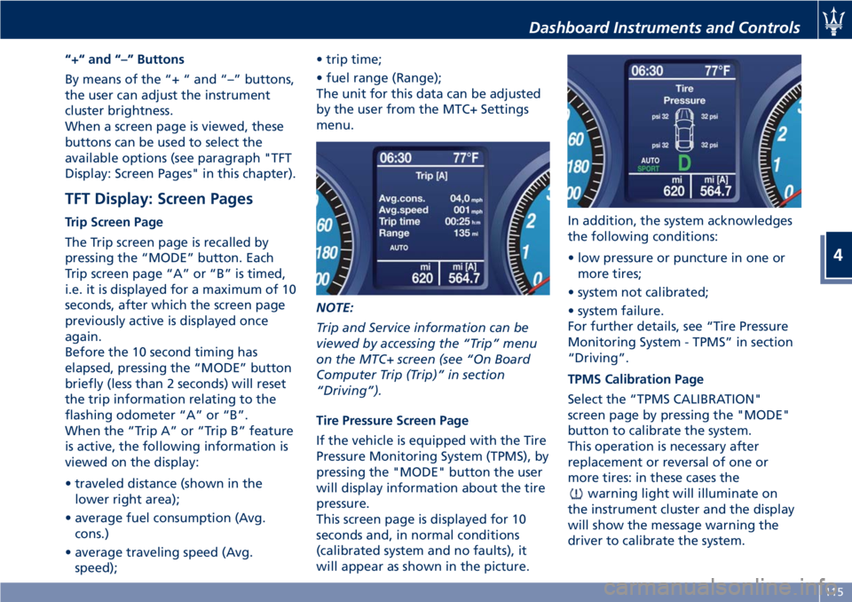
Tire Pressure Screen Page
If the vehicle is equipped with the Tire
Pressure Monitoring System (TPMS), by
pressing the "MODE" button the user
will display information about the tire
pressure.
This screen page is displayed for 10
seconds and, in normal conditions
(calibrated system and no faults), it
will appear as shown in the picture.In addition, the system acknowledges
the following conditions:
• low pressure or puncture in one or
more tires;
• system not calibrated;
• system failure.
For further details, see “Tire Pressure
Monitoring System - TPMS” in section
“Driving”.
TPMS Calibration Page
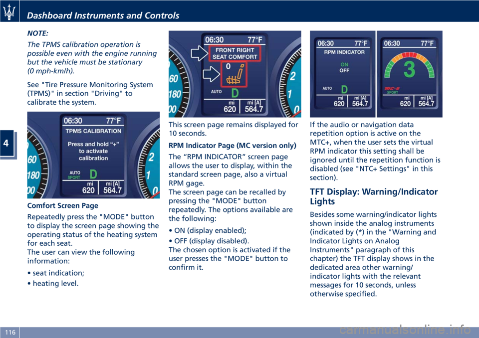
Select the “TPMS CALIBRATION"
screen page by pressing the "MODE"
button to calibrate the system.
This operation is necessary after
replacement or reversal of one or
more tires: in these cases the
warning light will illuminate on
the instrument cluster and the display
will show the message warning the
driver to calibrate the system.
Dashboard Instruments and Controls
4
115
Page 120 of 286
NOTE:
The TPMS calibration operation is
possible even with the engine running
but the vehicle must be stationary
(0 mph-km/h).
See "Tire Pressure Monitoring System
(TPMS)" in section "Driving" to
calibrate the system.
Comfort Screen Page
Repeatedly press the "MODE" button
to display the screen page showing the
operating status of the heating system
for each seat.
The user can view the following
information:
• seat indication;
• heating level.This screen page remains displayed for
10 seconds.
RPM Indicator Page (MC version only)
The “RPM INDICATOR” screen page
allows the user to display, within the
standard screen page, also a virtual
RPM gage.
The screen page can be recalled by
pressing the "MODE" button
repeatedly. The options available are
the following:
• ON (display enabled);
• OFF (display disabled).
The chosen option is activated if the
user presses the "MODE" button to
confirm it.If the audio or navigation data
repetition option is active on the
MTC+, when the user sets the virtual
RPM indicator this setting shall be
ignored until the repetition function is
disabled (see "NTC+ Settings" in this
section).
TFT Display: Warning/Indicator
Lights
Besides some warning/indicator lights
shown inside the analog instruments
(indicated by (*) in the "Warning and
Indicator Lights on Analog
Instruments" paragraph of this
chapter) the TFT display shows in the
dedicated area other warning/
indicator lights with the relevant
messages for 10 seconds, unless
otherwise specified.
Dashboard Instruments and Controls
4
116
Page 151 of 286
5 – Driving
Normal Starting of the Engine............................. 148
Automatic Transmission.................................. 150
Onboard Computer (Trip)................................ 157
Drive Mode........................................... 159
Parking Brake......................................... 164
Parking.............................................. 166
Brake and Stability Control System......................... 167
Using the Brakes....................................... 171
Use of the Engine...................................... 173
Cruise Control (CC)...................................... 175
Tires - General Information............................... 177
Tire Pressure Monitoring System - TPMS...................... 184
Fuel Requirements...................................... 189
Refueling............................................. 192
Driving Conditions...................................... 194
Pollution Control Devices................................. 197
147
Page 181 of 286
• by turning the engine off; or
• by turning ON/OFF switch to "OFF"
position.
Warnings while Driving with CC
WARNING!
•When driving with CC activated, do
not shift to N (Neutral) position. It is
advisable to activate CC only when
traffic and road conditions permit
safe use of this device, that is: on
straight and dry roads, expressways
or highways, smooth flowing traffic
and smooth asphalt. Do not activate
this device when driving in town or
in heavy traffic.
•CC can only be activated at speeds
exceeding 19 mph (30 km/h).
•CC can only be activated in 4th, 5th
or 6th gear, depending upon the
vehicle speed.
•When driving downhill with the CC
activated, the vehicle may pick up
speed slightly exceeding the speed
stored, due to the change in the
engine load.
•In the event of malfunctioning or
failure of CC, turn ON/OFF switch to
"OFF" position and contact the
Authorized Maserati Dealer afterhaving checked that the relative
fuse is in proper working order.
•ON/OFF switch can be always left at
"ON" position without damaging
the CC. In any case, it is advisable to
deactivate the CC when it is not in
use. Turn ON/OFF switch to "OFF"
position to prevent any speeds from
being unintentionally stored.
Tires - General
Information
Tire Safety Information
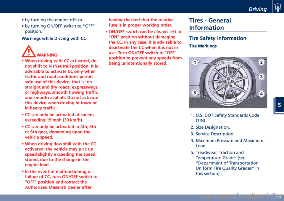
Tire Markings
1. U.S. DOT Safety Standards Code
(TIN).
2. Size Designation.
3. Service Description.
4. Maximum Pressure and Maximum
Load.
5. Treadwear, Traction and
Temperature Grades (see
“Department of Transportation
Uniform Tire Quality Grades” in
this section).
Driving
5
177
Page 182 of 286
Tire Sizing Chart
EXAMPLE: P285/40 ZR19 (100Y) XL or
285/40 ZR19 (Y100) XL
Size Designation:
P= Passenger car tire size based on
U.S. design standards
“...blank...”= Passenger car tire
based on European design standards
285= Section width in millimeters
(mm)
40= Aspect ratio in percent (%) —
Ratio of section height to section
width of tire
ZR= Construction Code
• Z: means a tire usable at speeds
greater than 150 mph (240 km/h)
• R: means radial construction
19= Rim diameter in inches (in)
Service Description:
100= Load Index — A numerical
code associated with the maximum
load a tire can carry
Y= Speed Symbol — A symbol
indicating the range of speeds at
which a tire can carry a load
corresponding to its load index
under certain operating conditions.
The maximum speed corresponding
to the speed symbol should only be
achieved under specified operating
conditions (i.e., tire pressure, vehicle
loading, road conditions, and posted
speed limits)
Load Identification:
“...blank...”= Absence of any text on
the sidewall of the tire indicates a
Standard Load (SL) tire
XL= Extra Load (or reinforced) tire
LL= Light Load tire
Tire Identification Number (TIN)
The TIN may be found on one or both
sides of the tire, however the date
code may only be on one side. Tires
with white sidewalls will have the full
TIN, including the date code, located
on the white sidewall side of the tire.Look for the TIN on the outboard side
of black sidewall tires as mounted on
the vehicle. If the TIN is not found on
the outboard side, then you will find it
on the inboard side of the tire.
EXAMPLE: DOT MA L9 ABCD 0313
DOT= Department of Transportation
— This symbol certifies that the tire is
in compliance with the U.S.
Department of Transportation tire
safety standards and is approved for
highway use.
MA= Code representing the tire
manufacturing location (two digits).
L9= Code representing the tire size
(two digits).
ABCD= Code used by the tire
manufacturer (one to four digits).
03= Number representing the week
in which the tire was manufactured
(two digits). In this case, 03 means
the 3
rdweek.
13= Number representing the year
in which the tire was manufactured
(two digits). In this case, 13 means
the year 2013.
Driving
5
178
Page 183 of 286
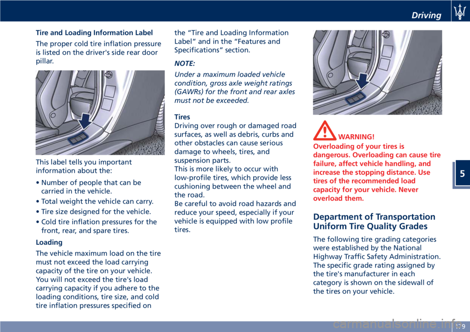
Tire and Loading Information Label
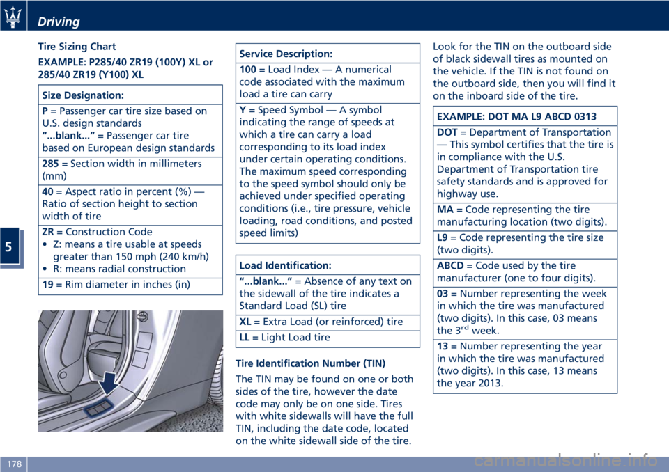
The proper cold tire inflation pressure
is listed on the driver's side rear door
pillar.
This label tells you important
information about the:
• Number of people that can be
carried in the vehicle.
• Total weight the vehicle can carry.
• Tire size designed for the vehicle.
• Cold tire inflation pressures for the
front, rear, and spare tires.
Loading
The vehicle maximum load on the tire
must not exceed the load carrying
capacity of the tire on your vehicle.
You will not exceed the tire's load
carrying capacity if you adhere to the
loading conditions, tire size, and cold
tire inflation pressures specified onthe “Tire and Loading Information
Label” and in the “Features and
Specifications” section.
NOTE:
Under a maximum loaded vehicle
condition, gross axle weight ratings
(GAWRs) for the front and rear axles
must not be exceeded.
Tires
Driving over rough or damaged road
surfaces, as well as debris, curbs and
other obstacles can cause serious
damage to wheels, tires, and
suspension parts.
This is more likely to occur with
low-profile tires, which provide less
cushioning between the wheel and
the road.
Be careful to avoid road hazards and
reduce your speed, especially if your
vehicle is equipped with low profile
tires.
WARNING!
Overloading of your tires is
dangerous. Overloading can cause tire
failure, affect vehicle handling, and
increase the stopping distance. Use
tires of the recommended load
capacity for your vehicle. Never
overload them.
Department of Transportation
Uniform Tire Quality Grades
The following tire grading categories
were established by the National
Highway Traffic Safety Administration.
The specific grade rating assigned by
the tire's manufacturer in each
category is shown on the sidewall of
the tires on your vehicle.
Driving
5
179