power steering MASERATI LEVANTE 2019 Owners Manual
[x] Cancel search | Manufacturer: MASERATI, Model Year: 2019, Model line: LEVANTE, Model: MASERATI LEVANTE 2019Pages: 436, PDF Size: 15.24 MB
Page 37 of 436
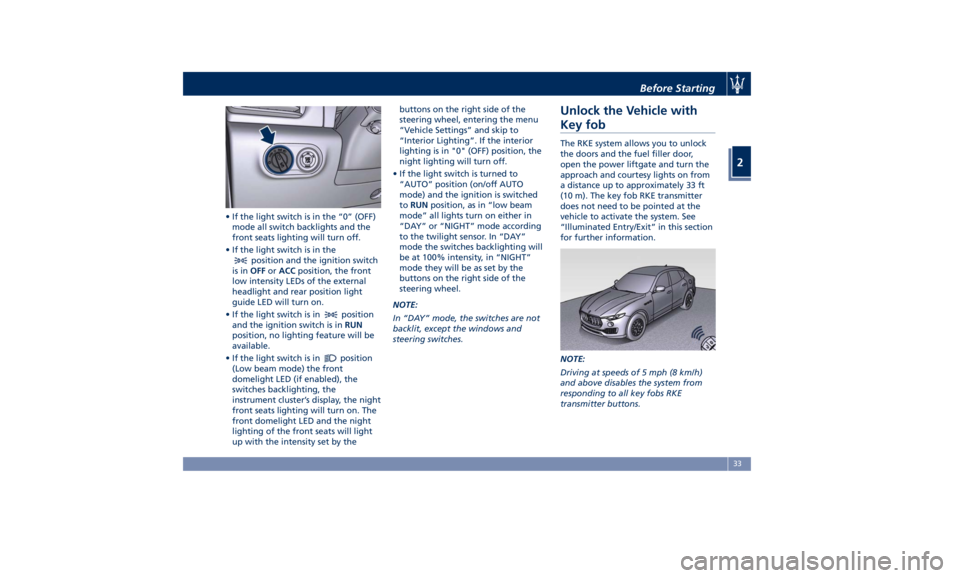
• If the light switch is in the “0” (OFF)
mode all switch backlights and the
front seats lighting will turn off.
• If the light switch is in the
position and the ignition switch
is in OFF or ACC position, the front
low intensity LEDs of the external
headlight and rear position light
guide LED will turn on.
• If the light switch is in
position
and the ignition switch is in RUN
position, no lighting feature will be
available.
• If the light switch is in
position
(Low beam mode) the front
domelight LED (if enabled), the
switches backlighting, the
instrument cluster’s display, the night
front seats lighting will turn on. The
front domelight LED and the night
lighting of the front seats will light
up with the intensity set by the buttons on the right side of the
steering wheel, entering the menu
“Vehicle Settings” and skip to
“Interior Lighting”. If the interior
lighting is in "0" (OFF) position, the
night lighting will turn off.
• If the light switch is turned to
“AUTO” position (on/off AUTO
mode) and the ignition is switched
to RUN position, as in “low beam
mode” all lights turn on either in
“DAY” or “NIGHT” mode according
to the twilight sensor. In “DAY”
mode the switches backlighting will
be at 100% intensity, in “NIGHT”
mode they will be as set by the
buttons on the right side of the
steering wheel.
NOTE:
In “DAY” mode, the switches are not
backlit, except the windows and
steering switches.Unlock the Vehicle with
Key fob The RKE system allows you to unlock
the doors and the fuel filler door,
open the power liftgate and turn the
approach and courtesy lights on from
a distance up to approximately 33 ft
(10 m). The key fob RKE transmitter
does not need to be pointed at the
vehicle to activate the system. See
“Illuminated Entry/Exit” in this section
for further information.
NOTE:
Driving at speeds of 5 mph (8 km/h)
and above disables the system from
responding to all key fobs RKE
transmitter buttons.Before Starting
2
33
Page 41 of 436
Remote Start System On the vehicles that are equipped
with this system, the key fob RKE
transmitter enables to start the engine
conveniently from outside the vehicle
while still maintaining security. The
system has a range of approximately
300 ft (91 m). Obstructions between
the vehicle and the key fob may
reduce this range.
NOTE:
Changes or modifications not
expressly approved by the party
responsible for compliance could void
the user's authority to operate the
equipment.
If your RKE transmitter fails to operate
from a normal distance, check for
these conditions:
• A weak battery in the RKE
transmitter. The expected life of the
battery is a minimum of three years.
• Closeness to a radio transmitter such
as a radio station tower, airport
transmitter, and some mobile or CB
radio.
• Obstructions between the vehicle
and the Key Fob. How to use Remote Start All of the following conditions must
be met before the engine will remote
start:
• System not disabled from previous
remote start event.
• Vehicle theft alarm not active.
• Vehicle Panic mode not active.
• Doors closed.
• Hood closed.
• Power liftgate closed.
• Hazard lights switched off.
• Brake pedal not pressed.
• Battery at an acceptable charge
level.
• The shift lever is in P (Park) position.
• The vehicle transmission is in
automatic mode.
• The remote start has not been
activated yet two consecutive times.
If EPB (Electric Parking Brake) is not
selected, at key-off in some conditions
the remote start system may not allow
engine to start. We suggest to set
“Auto Apply On” function through
the switch on the right-side of the
steering wheel (refer to “Instrument
Cluster” in section “Dashboard
Instrument and Controls”). WARNING!
• Do not start or run an engine in a
closed garage or confined area.
Exhaust gas contains Carbon
Monoxide (CO) which is odorless
and colorless
• Keep key fobs RKE transmitter away
from children. Operation of the
Remote Start System, windows,
door locks or other controls could
cause serious injury or death.
Engine Remote Start Abort
Message on Instrument Cluster The following messages will display on
the instrument cluster if the vehicle
fails to remote start or exits remote
start prematurely:
• “Remote Start Canceled Door
Open”.
• “Remote Start Canceled Liftgate
Open”.
• “Remote Start Canceled Fuel Low”.
• “Remote Start Canceled Time
Expired”.
• “Remote Start Disabled Start Vehicle
to Reset”.Before Starting
2
37
Page 70 of 436
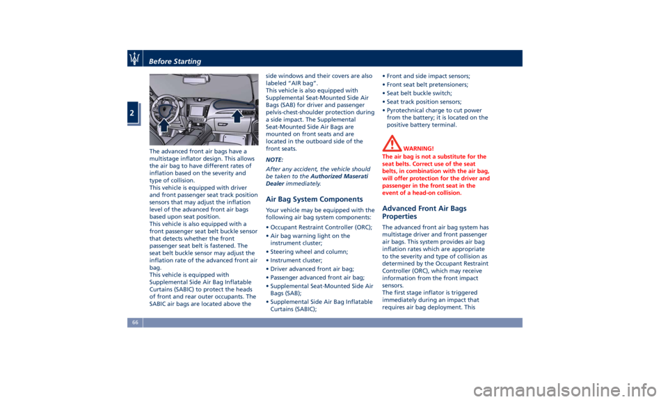
The advanced front air bags have a
multistage inflator design. This allows
the air bag to have different rates of
inflation based on the severity and
type of collision.
This vehicle is equipped with driver
and front passenger seat track position
sensors that may adjust the inflation
level of the advanced front air bags
based upon seat position.
This vehicle is also equipped with a
front passenger seat belt buckle sensor
that detects whether the front
passenger seat belt is fastened. The
seat belt buckle sensor may adjust the
inflation rate of the advanced front air
bag.
This vehicle is equipped with
Supplemental Side Air Bag Inflatable
Curtains (SABIC) to protect the heads
of front and rear outer occupants. The
SABIC air bags are located above the side windows and their covers are also
labeled “AIR bag”.
This vehicle is also equipped with
Supplemental Seat-Mounted Side Air
Bags (SAB) for driver and passenger
pelvis-chest-shoulder protection during
a side impact. The Supplemental
Seat-Mounted Side Air Bags are
mounted on front seats and are
located in the outboard side of the
front seats.
NOTE:
After any accident, the vehicle should
be taken to the Authorized Maserati
Dealer immediately.
Air Bag System Components Your vehicle may be equipped with the
following air bag system components:
• Occupant Restraint Controller (ORC);
• Air bag warning light on the
instrument cluster;
• Steering wheel and column;
• Instrument cluster;
• Driver advanced front air bag;
• Passenger advanced front air bag;
• Supplemental Seat-Mounted Side Air
Bags (SAB);
• Supplemental Side Air Bag Inflatable
Curtains (SABIC); • Front and side impact sensors;
• Front seat belt pretensioners;
• Seat belt buckle switch;
• Seat track position sensors;
• Pyrotechnical charge to cut power
from the battery; it is located on the
positive battery terminal.
WARNING!
The air bag is not a substitute for the
seat belts. Correct use of the seat
belts, in combination with the air bag,
will offer protection for the driver and
passenger in the front seat in the
event of a head-on collision.
Advanced Front Air Bags
Properties The advanced front air bag system has
multistage driver and front passenger
air bags. This system provides air bag
inflation rates which are appropriate
to the severity and type of collision as
determined by the Occupant Restraint
Controller (ORC), which may receive
information from the front impact
sensors.
The first stage inflator is triggered
immediately during an impact that
requires air bag deployment. ThisBefore Starting
2
66
Page 71 of 436
inflation rate is used in less severe
collisions. A higher energy output,
inflation rate, is used for more severe
collisions.
CAUTION!
• The airbag system must be ready to
protect you in a collision. The
Occupant Restraint Controller (ORC)
monitors the internal circuits and
interconnecting wiring associated with
electrical Air Bag System Components
listed below:
– Occupant Restraint Controller
(ORC)
– Airbag Warning light on the
instrument cluster
– Steering Wheel and Column
– Instrument Cluster
– Driver advanced front air bag
– Passenger advanced front air bag
– Supplemental Seat-Mounted Side
Air Bags (SAB) Air Bags
– Supplemental Side Air Bag
Inflatable Curtains (SABIC)
– Front and side Impact Sensors
– Front seat belt pretensioners
– Seat Belt Buckle Switch
– Seat Track Position Sensors
– Pyrotechnical charge to cut the
power from the battery: it is located on the positive battery
terminal
• The electronic control unit provides
for the activation of the
pretensioners, front air bags or side
air bags (front and rear) based on
different criteria, according to the
type of impact. Failure of one or
more systems to activate is not
indicative of a system malfunction.
• The front and/or lateral air bags may
inflate if the vehicle suffers a violent
impact involving the underbody
area, for example in case of violent
impacts against steps, sidewalks,
speed bumps, or when the vehicle
falls into potholes, or similar.
WARNING!
• No objects should be placed over or
near the air bag on the instrument
panel or steering wheel because any
such objects could cause harm if the
vehicle is in a collision severe
enough to cause the air bag to
inflate.
• Do not place anything on or around
the air bag covers or attempt to
open them manually. You may
damage the air bags and you could be injured because the air bags may
no longer be functional. The
protective covers for the air bag are
designed to open only when the air
bags are inflating.
• Always drive with your hands on
the steering wheel rim, so that the
air bag can inflate freely if required.
During the drive your back must be
as upright as comfort allows and be
against the seat back with the seat
belt properly fastened.
• Do not apply stickers or other
objects on the steering wheel, on
the dashboard in the passenger’s
side air bag area, on roof side trims
or on the seats.
• Do not travel with objects in your
lap, in front of your chest or
especially with a pipe, pencil or
other objects in your mouth. In the
event of a collision, the intervention
of the air bag could result in serious
injury.
• EXTREME HAZARD! Do not place a
rearward-facing infant seat onto the
front seat (see warning plate on the
dashboard and above and behind
the sun visors). Deployment of the
air bag in an accident could causeBefore Starting
2
67
Page 97 of 436
3 – Understanding the Vehicle Interior Components ..................................... 94
Front Power Seats ....................................... 97
Driver Memory Seat ..................................... 101
Rear Seats ............................................ 103
Head Restraints ........................................ 105
Steering Wheel Adjustment ............................... 108
Adjustable Pedals (if equipped) ............................ 110
Rearview Mirrors ....................................... 110
Lights ................................................ 113
Wipers and Washers .................................... 129
Interior Features ....................................... 133
Cargo Area ........................................... 139
Front to Back Roof Rails (optional) .......................... 147
Power Sunroof with Sunshade (optional) ..................... 148
HomeLink (optional) .................................... 150
Air Conditioning Distribution ............................. 154
93
Page 99 of 436
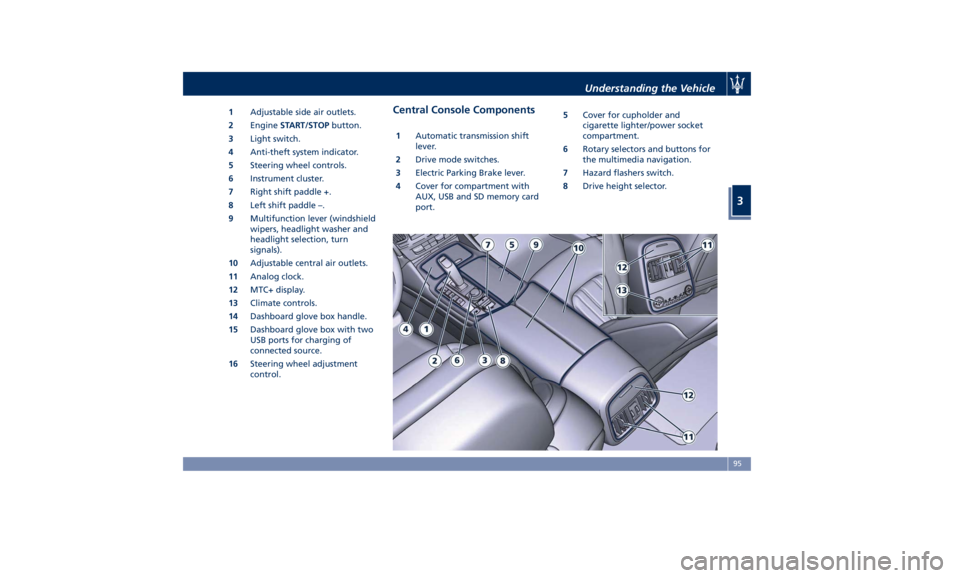
1 Adjustable side air outlets.
2 Engine START/STOP button.
3 Light switch.
4 Anti-theft system indicator.
5 Steering wheel controls.
6 Instrument cluster.
7 Right shift paddle +.
8 Left shift paddle –.
9 Multifunction lever (windshield
wipers, headlight washer and
headlight selection, turn
signals).
10 Adjustable central air outlets.
11 Analog clock.
12 MTC+ display.
13 Climate controls.
14 Dashboard glove box handle.
15 Dashboard glove box with two
USB ports for charging of
connected source.
16 Steering wheel adjustment
control. Central Console Components 1 Automatic transmission shift
lever.
2 Drive mode switches.
3 Electric Parking Brake lever.
4 Cover for compartment with
AUX, USB and SD memory card
port. 5 Cover for cupholder and
cigarette lighter/power socket
compartment.
6 Rotary selectors and buttons for
the multimedia navigation.
7 Hazard flashers switch.
8 Drive height selector.Understanding the Vehicle
3
95
Page 100 of 436
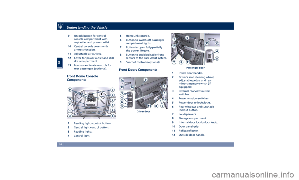
9 Unlock button for central
console compartment with
cupholder and power outlet.
10 Central console covers with
armrest function.
11 Adjustable air outlets.
12 Cover for power outlet and USB
slots compartment.
13 Four-zone climate controls for
rear passengers (optional).
Front Dome Console
Components
1 Reading lights control button.
2 Central light control button.
3 Reading lights.
4 Central light. 5 HomeLink controls.
6 Button to switch off passenger
compartment lights.
7 Button to open fully/partially
the power liftgate.
8 Button to enable/disable front
sensors of the Park Assist system.
9 Sunroof controls (optional).
Front Doors Components 1 Inside door handle.
2 Driver’s seat, steering wheel,
adjustable pedals and rear
mirrors memory switch (if
equipped).
3 External rearview mirrors
switches.
4 Power window switches.
5 Power door unlocks/locks.
6 Rear windows and sunshade
lockout button.
7 Loudspeakers.
8 Storage compartment.
9 Internal door lock/unlock knob.
10 Door panel grip.
11 Reflex reflector.
12 Outside door handle.Driver door Passenger doorUnderstanding the Vehicle
3
96
Page 105 of 436
Driver Memory Seat This feature allows the driver to store
up to two different memory profiles
for easy recall through a memory
switch. Each memory profile contains
desired position settings for the driver
seat, external side mirrors, adjustable
pedals (optional), and power tilt and
telescopic steering column and a set of
programmed radio stations.
Your key fob RKE transmitter can also
be set to recall the same positions by
pressing the
button.
NOTE:
• Only one key fob RKE transmitter
can be linked to each of the memory
positions.
• “Passive Entry” door handles cannot
be linked to the memory function.
Use either the memory recall switch
or the key fob RKE transmitter (if
linked to the memory feature) to
recall memory positions 1 or 2.
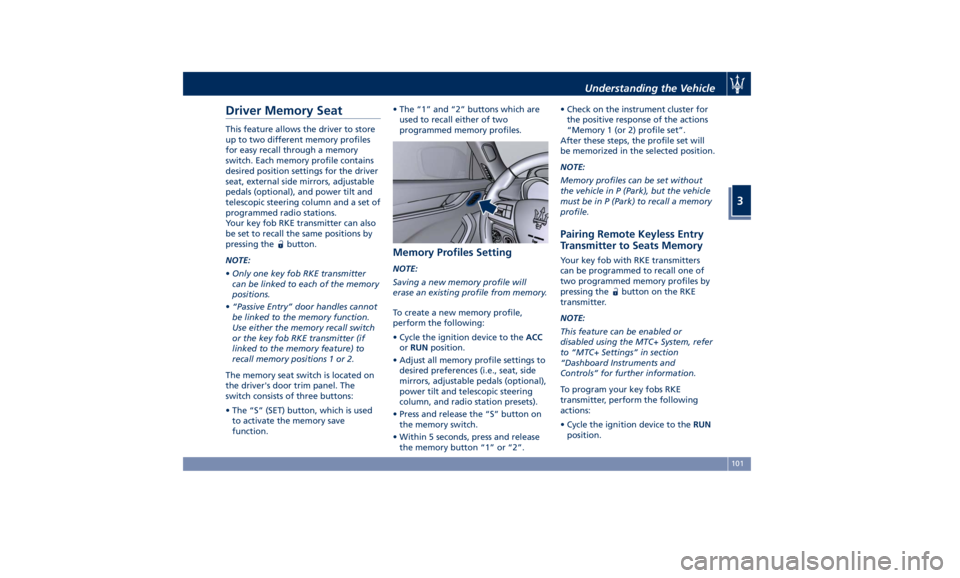
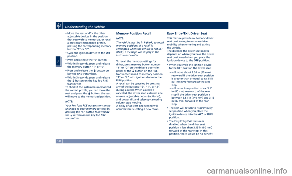
The memory seat switch is located on
the driver's door trim panel. The
switch consists of three buttons:
• The “S” (SET) button, which is used
to activate the memory save
function. • The “1” and “2” buttons which are
used to recall either of two
programmed memory profiles.
Memory Profiles Setting NOTE:
Saving a new memory profile will
erase an existing profile from memory.
To create a new memory profile,
perform the following:
• Cycle the ignition device to the ACC
or RUN position.
• Adjust all memory profile settings to
desired preferences (i.e., seat, side
mirrors, adjustable pedals (optional),
power tilt and telescopic steering
column, and radio station presets).
• Press and release the “S” button on
the memory switch.
• Within 5 seconds, press and release
the memory button “1” or “2”. • Check on the instrument cluster for
the positive response of the actions
“Memory 1 (or 2) profile set”.
After these steps, the profile set will
be memorized in the selected position.
NOTE:
Memory profiles can be set without
the vehicle in P (Park), but the vehicle
must be in P (Park) to recall a memory
profile.
Pairing Remote Keyless Entry
Transmitter to Seats Memory Your key fob with RKE transmitters
can be programmed to recall one of
two programmed memory profiles by
pressing the
button on the RKE
transmitter.
NOTE:
This feature can be enabled or
disabled using the MTC+ System, refer
to “MTC+ Settings” in section
“Dashboard Instruments and
Controls” for further information.
To program your key fobs RKE
transmitter, perform the following
actions:
• Cycle the ignition device to the RUN
position.Understanding the Vehicle
3
101
Page 106 of 436
• Move the seat and/or the other
adjustable devices in the position
that you wish to memorize, or recall
a previously memorized profile,
pressing the corresponding memory
button “1” or “2”.
• Cycle the ignition device to the OFF
position.
• Press and release the “S” button.
• Within 5 seconds, press and release
the memory button “1” or “2”.
• Press and release the
button on
key fob RKE transmitter.
• Within 3 seconds, press and release
the
button on the key fob RKE
transmitter.
To check if the system has memorized
the correct profile, you can move the
seat and press the
button: the seat
will move to the memorized position.
NOTE:
Your key fobs RKE transmitter can be
unlinked to your memory settings by
pressing the “S” button followed by
the
button on the key fob RKE
transmitter. Memory Position Recall NOTE:
The vehicle must be in P (Park) to recall
memory positions. If a recall is
attempted when the vehicle is not in P
(Park), a message will display in the
instrument cluster.
To recall the memory settings for
driver, press memory button number
“1” or “2” on the driver's door trim
panel or the
button on the RKE
transmitter linked to memory position
“1” or “2” with ignition device in the
RUN position.
A recall can be canceled by pressing
any of the buttons (“S”, “1”, or “2”)
during a recall. When a recall is
canceled, the driver seat, external side
mirrors, adjustable pedals (optional),
and power tilt and telescopic steering
column stop moving.
A delay of at least one second will
occur before selecting a new recall. Easy Entry/Exit Driver Seat This feature provides automatic driver
seat positioning to enhance driver
mobility when entering and exiting
the vehicle.
The distance the driver seat moves
depends on where you have the driver
seat positioned when you place the
ignition device to the OFF position.
• When you cycle the ignition device
to the OFF position the driver seat:
• will move about 2.36 in (60 mm)
rearward if the driver seat position
is greater than or equal to ca. 5.51
in (140 mm) forward of the rear
stop;
• will move to a position of ca. 3.15
in (80 mm) rearward of the rear
stop if the driver seat position is
between 5.51 in (140 mm) and 3.15
in (80 mm) forward of the rear
stop.
• The seat will return to its previously
set position when you place the
ignition device into the ACC or RUN
position.
• The Easy Entry/Exit feature is
disabled when the driver seat
position is less than 3.15 in (80 mm)
forward of the rear stop. In this
position, there would be no benefitUnderstanding the Vehicle
3
102
Page 112 of 436
• Tilt the seat back to the upright
position (see “CArgo Area” in this
section).
• Reposition the head restraint to the
appropriate height for the passenger.
WARNING!
• A loose head restraint thrown
forward in a collision or hard stop
could cause serious injury or death
to occupants of the vehicle. Always
securely stow removed head
restraints in a location outside the
occupant compartment.
• ALL the head restraints MUST be
reinstalled in the vehicle to properly
protect the occupants. Follow the
re-installation instructions above
prior to operating the vehicle or
occupying a seat. Steering Wheel
Adjustment This feature allows you to tilt the
steering column upward or downward
or to lengthen or shorten it in order to
adjust the steering wheel to an
optimized position.
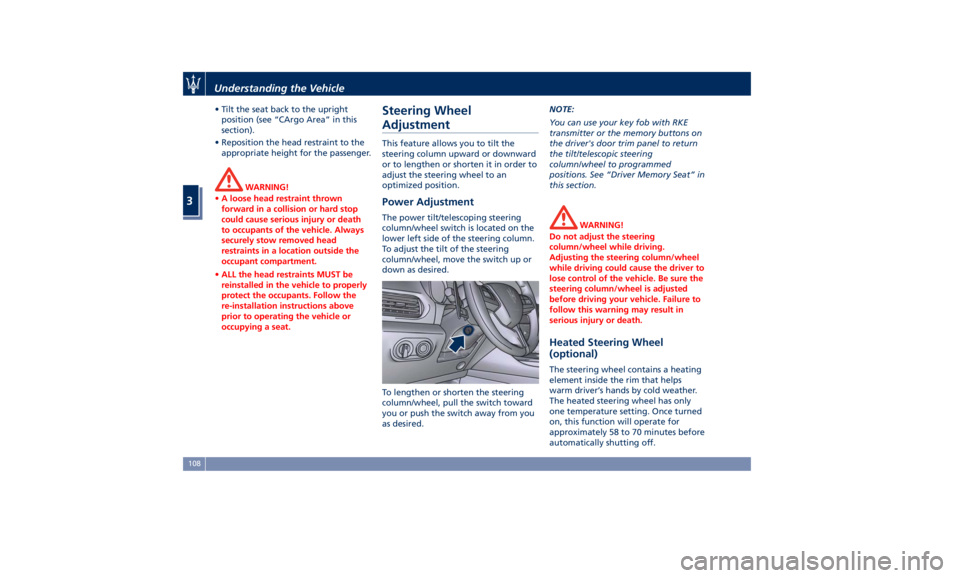
Power Adjustment The power tilt/telescoping steering
column/wheel switch is located on the
lower left side of the steering column.
To adjust the tilt of the steering
column/wheel, move the switch up or
down as desired.
To lengthen or shorten the steering
column/wheel, pull the switch toward
you or push the switch away from you
as desired. NOTE:
You can use your key fob with RKE
transmitter or the memory buttons on
the driver's door trim panel to return
the tilt/telescopic steering
column/wheel to programmed
positions. See “Driver Memory Seat” in
this section.
WARNING!
Do not adjust the steering
column/wheel while driving.
Adjusting the steering column/wheel
while driving could cause the driver to
lose control of the vehicle. Be sure the
steering column/wheel is adjusted
before driving your vehicle. Failure to
follow this warning may result in
serious injury or death.
Heated Steering Wheel
(optional) The steering wheel contains a heating
element inside the rim that helps
warm driver’s hands by cold weather.
The heated steering wheel has only
one temperature setting. Once turned
on, this function will operate for
approximately 58 to 70 minutes before
automatically shutting off.Understanding the Vehicle
3
108