valve cover MASERATI LEVANTE 2019 Owners Manual
[x] Cancel search | Manufacturer: MASERATI, Model Year: 2019, Model line: LEVANTE, Model: MASERATI LEVANTE 2019Pages: 436, PDF Size: 15.24 MB
Page 356 of 436
(Continued)
go back to normal operation.
NOTE:
The compact spare wheel is supplied in
aluminum or steel: the pictures show
the one in aluminum.
The compact spare wheel is stored in
the trunk and is supplied deflated in
order to limit the amount of space
occupied. An electric compressor is also
provided for inflating. In the event of
a tire puncture, proceed as follows.
• Stop the vehicle in a place that does
not constitute a danger to traffic and
where the wheel can be changed
safely. The vehicle must be level and
on firm ground.
• Select the P (Park) mode and then
engage manually the electric parking
brake and move the ignition switch
to OFF position.
• If necessary, turn the hazard warning
flashers on and place the warning
triangle (if equipped) at the required
distance.
WARNING!
• The jack should be used on level firm
ground wherever possible. • It is recommended that the wheels
of the vehicle be chocked, and that
no person should remain in a vehicle
that is being jacked.
• If the vehicle has been stopped on a
slope or an uneven surface, place
chocks or other suitable items in
front of or behind the wheels to
stop the vehicle from moving.
• Never start or run the engine with
the vehicle on a jack.
• No person should place any portion
of their body under a vehicle that is
supported by a jack.
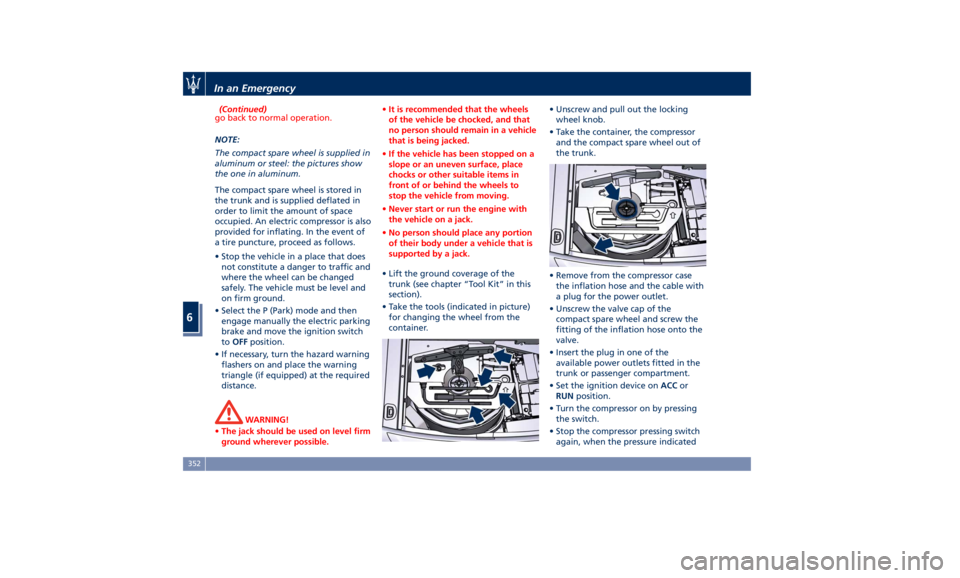
• Lift the ground coverage of the
trunk
(see chapter “T ool Kit” in this
section).
• Take the tools (indicated in picture)
for changing the wheel from the
container. • Unscrew and pull out the locking
wheel knob.
• Take the container, the compressor
and the compact spare wheel out of
the trunk.
• Remove from the compressor case
the inflation hose and the cable with
a plug for the power outlet.
• Unscrew the valve cap of the
compact spare wheel and screw the
fitting of the inflation hose onto the
valve.
• Insert the plug in one of the
available power outlets fitted in the
trunk or passenger compartment.
• Set the ignition device on ACC or
RUN position.
• Turn the compressor on by pressing
the switch.
• Stop the compressor pressing switch
again, when the pressure indicatedIn an Emergency
6
352
Page 357 of 436
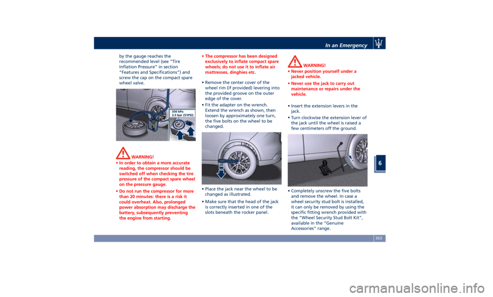
by the gauge reaches the
recommended level (see “Tire
Inflation Pressure” in section
“Features and Specifications”) and
screw the cap on the compact spare
wheel valve.
WARNING!
• In order to obtain a more accurate
reading, the compressor should be
switched off when checking the tire
pressure of the compact spare wheel
on the pressure gauge.
• Do not run the compressor for more
than 20 minutes: there is a risk it
could overheat. Also, prolonged
power absorption may discharge the
battery, subsequently preventing
the engine from starting. • The compressor has been designed
exclusively to inflate compact spare
wheels; do not use it to inflate air
mattresses, dinghies etc.
• Remove the center cover of the
wheel
rim (if provided) levering into
the provided groove on the outer
edge of the cover.
• Fit the adapter on the wrench.
Extend the wrench as shown, then
loosen by approximately one turn,
the five bolts on the wheel to be
changed.
• Place the jack near the wheel to be
changed as illustrated.
• Make sure that the head of the jack
is correctly inserted in one of the
slots beneath the rocker panel. WARNING!
• Never position yourself under a
jacked vehicle.
• Never use the jack to carry out
maintenance or repairs under the
vehicle.
• Insert the extension levers in the
jack.
•
Turn clockwise
the extension lever of
the jack until the wheel is raised a
few centimeters off the ground.
• Completely unscrew the five bolts
and remove the wheel. In case a
wheel security stud bolt is installed,
it can only be removed by using the
specific fitting wrench provided with
the “Wheel Security Stud Bolt Kit”,
available in the “Genuine
Accessories” range.In an Emergency
6
353
Page 359 of 436
will be compromised. Avoid
accelerating to full speed, heavy
braking and fast cornering.
• The compact spare wheel must be
inflated to the recommended tire
pressure (see “Tire Inflation
Pressure” in section “Features and
Specifications”).
• For safety reasons, it is absolutely
forbidden to drive with more than
one compact spare wheel fitted on
the vehicle.
• Snow chains cannot be fitted on the
compact spare wheel.
• The spare wheel can travel a
maximum of 1,800 mi (3.000 km).
To Refit the Standard Wheel with
Repair
ed or Replaced Tire
• Following the procedure and the
caution described above, raise the
vehicle and remove the compact
spare wheel reusing the supplied
wrench with adapter, suitably
extended.
• Fit the standard wheel with repaired
or replaced tire.
• Tighten the original bolts on the
wheel.
• Lower the vehicle and remove the
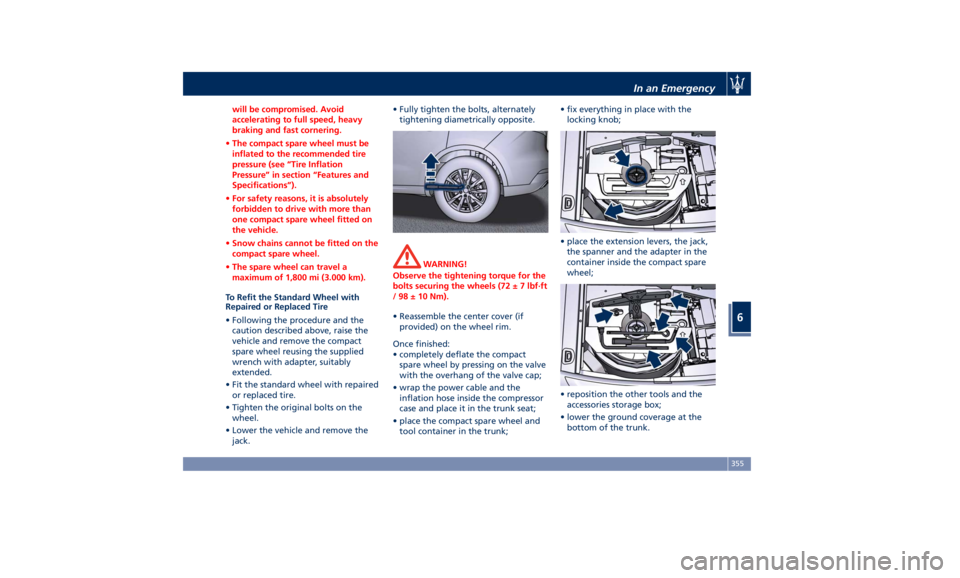
jack. • Fully tighten the bolts, alternately
tightening diametrically opposite.
WARNING!
Observe the tightening torque for the
bolts securing the wheels (72 ± 7 lbf·ft
/ 98 ± 10 Nm).
• Reassemble the center cover (if
provided)
on the wheel
rim.
Once finished:
• completely deflate the compact
spare wheel by pressing on the valve
with the overhang of the valve cap;
• wrap the power cable and the
inflation hose inside the compressor
case and place it in the trunk seat;
• place the compact spare wheel and
tool container in the trunk; • fix everything in place with the
locking knob;
• place the extension levers, the jack,
the spanner and the adapter in the
container inside the compact spare
wheel;
• reposition the other tools and the
accessories storage box;
• lower the ground coverage at the
bottom of the trunk.In an Emergency
6
355
Page 391 of 436
• on the fuse and relay box located in
a covered area, under the dashboard
left side.
Integrated Power Module • To access the module it is necessary
to lift the hood (see “Hood
Operation” in section “Before
Starting”).
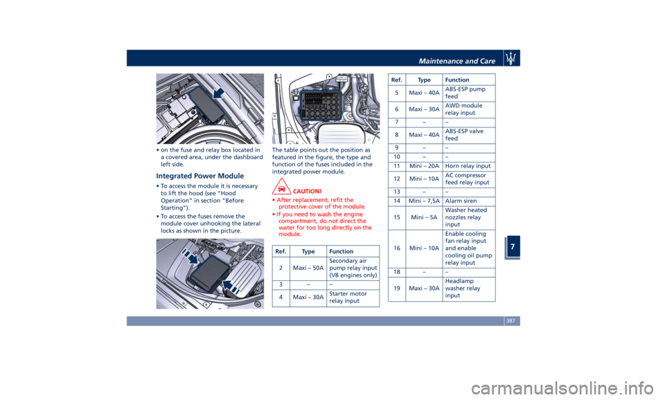
• To access the fuses remove the
module cover unhooking the lateral
locks as shown in the picture. The table points out the position as
featured in the figure, the type and
function of the fuses included in the
integrated power module.
CAUTION!
• After replacement, refit the
protective cover of the module.
• If you need to wash the engine
compartment, do not direct the
water for too long directly on the
module.
Ref. Type Function
2 Maxi – 50A Secondary air
pump relay input
(V8 engines only)
3––
4 Maxi – 30A Starter motor
relay input Ref. Type Function
5 Maxi – 40A ABS-ESP pump
feed
6 Maxi – 30A AWD module
relay input
7––
8 Maxi – 40A ABS-ESP valve
feed
9––
10 – –
11 Mini – 20A Horn relay input
12 Mini – 10A AC compressor
feed relay input
13 – –
14 Mini – 7,5A Alarm siren
15 Mini – 5A Washer heated
nozzles relay
input
16 Mini – 10A Enable cooling
fan relay input
and enable
cooling oil pump
relay input
18 – –
19 Maxi – 30A Headlamp
washer relay
inputMaintenance and Care
7
387
Page 393 of 436
Ref. Type Function
39 Mini – 7,5A Flow meters,
tank lackage,
canister, exhaust
by-pass valve
relay coil and air
shutter
48 – –
49 Mini – 10A Pedal brake
switch-TCM
module
50 Mini – 15A +30 PCM module
51 Mini – 30A Fuel pump relay
input
52 Mini – 5A Starter solenoid
signal for PCM
and voltage
stabilizer
53 Mini – 10A AWD module
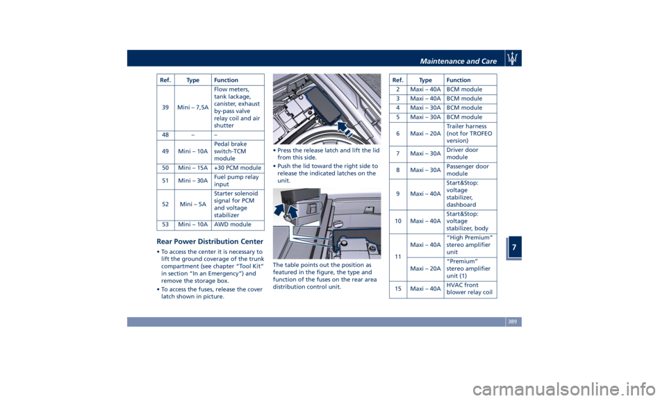
Rear Power Distribution Center • To access the center it is necessary to
lift the ground coverage of the trunk
compartment (see chapter “Tool Kit”
in section “In an Emergency”) and
remove the storage box.
• To access the fuses, release the cover
latch shown in picture. • Press the release latch and lift the lid
from this side.
• Push the lid toward the right side to
release the indicated latches on the
unit.
The table points out the position as
featured in the figure, the type and
function of the fuses on the rear area
distribution control unit. Ref. Type Function
2 Maxi – 40A BCM module
3 Maxi – 40A BCM module
4 Maxi – 30A BCM module
5 Maxi – 30A BCM module
6 Maxi – 20A Trailer harness
(not for TROFEO
version)
7 Maxi – 30A Driver door
module
8 Maxi – 30A Passenger door
module
9 Maxi – 40A Start&Stop:
voltage
stabilizer,
dashboard
10 Maxi – 40A Start&Stop:
voltage
stabilizer, body
11 Maxi – 40A “High Premium”
stereo amplifier
unit
Maxi – 20A “Premium”
stereo amplifier
unit (1)
15 Maxi – 40A HVAC front
blower relay coilMaintenance and Care
7
389