Starter MASERATI QUATTROPORTE 2019 Owners Manual
[x] Cancel search | Manufacturer: MASERATI, Model Year: 2019, Model line: QUATTROPORTE, Model: MASERATI QUATTROPORTE 2019Pages: 396, PDF Size: 13.9 MB
Page 223 of 396

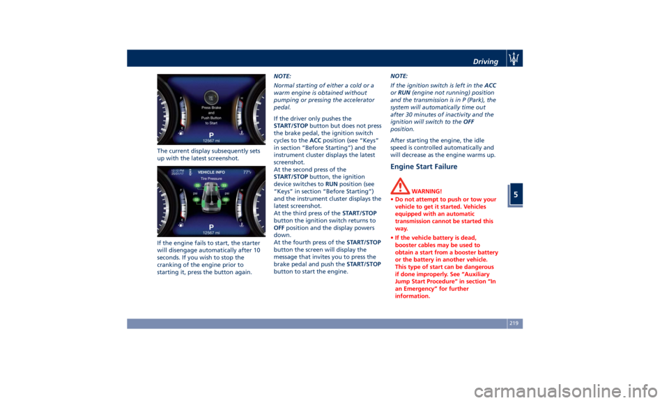
The current display subsequently sets
up with the latest screenshot.
If the engine fails to start, the starter
will disengage automatically after 10
seconds. If you wish to stop the
cranking of the engine prior to
starting it, press the button again. NOTE:
Normal starting of either a cold or a
warm engine is obtained without
pumping or pressing the accelerator
pedal.
If the driver only pushes the
START/STOP button but does not press
the brake pedal, the ignition switch
cycles to the ACC position (see “Keys”
in section “Before Starting”) and the
instrument cluster displays the latest
screenshot.
At the second press of the
START/STOP button, the ignition
device switches to RUN position (see
“Keys” in section “Before Starting”)
and the instrument cluster displays the
latest screenshot.
At the third press of the START/STOP
button the ignition switch returns to
OFF position and the display powers
down.
At the fourth press of the START/STOP
button the screen will display the
message that invites you to press the
brake pedal and push the START/STOP
button to start the engine. NOTE:
If the ignition switch is left in the ACC
or RUN (engine not running) position
and the transmission is in P (Park), the
system will automatically time out
after 30 minutes of inactivity and the
ignition will switch to the OFF
position.
After starting the engine, the idle
speed is controlled automatically and
will decrease as the engine warms up.
Engine Start Failure WARNING!
• Do not attempt to push or tow your
vehicle to get it started. Vehicles
equipped with an automatic
transmission cannot be started this
way.
• If the vehicle battery is dead,
booster cables may be used to
obtain a start from a booster battery
or the battery in another vehicle.
This type of start can be dangerous
if done improperly. See “Auxiliary
Jump Start Procedure” in section “In
an Emergency” for further
information.Driving
5
219
Page 327 of 396

CAUTION!
• To jump start a vehicle do not use a
portable battery, a booster pack or
any other booster source with a
system voltage greater than 14 Volts
or damage to the battery, starter
motor, alternator or electrical system
of the vehicle with the discharged
battery may occur.
• Do not use a battery charger for
emergency starting under any
circumstances. You could damage
the electronic systems, particularly
the control units managing the
ignition and fuel supply functions.
• If the battery is completely
discharged when the windows are
fully raised, open the door with the
utmost care; do not close the door
again until it is possible to lower the
window.
WARNING!
Always secure your vehicle by fully
applying the parking brake, before
activating the manual park release.
Activating the manual park release
could allow your vehicle to roll away if it is not secured by the parking
brake. Activating the manual park
release on an unsecured vehicle could
lead to serious injury or death for
those in or around the vehicle.
NOTE:
If
you need
to disconnect the battery
from the vehicle electrical system, see
“Maintenance — Free Battery” in
section “Maintenance and Care”).
WARNING!
California Proposition 65
Operating, servicing and maintaining
a passenger vehicle or off-road vehicle
can expose you to chemicals including
such as, engine exhaust, carbon
monoxide, phthalates and lead, that
which are known to the State of
California to cause cancer and birth
defects or other reproductive harm. To
minimize exposure, avoid breathing
exhaust, do not idle the engine except
as necessary, service your vehicle in a
well-ventilated area and wear gloves
or wash your hands frequently when
servicing your vehicle. For more
information go to: www.P65Warnings.ca.gov/passenger-
vehicle
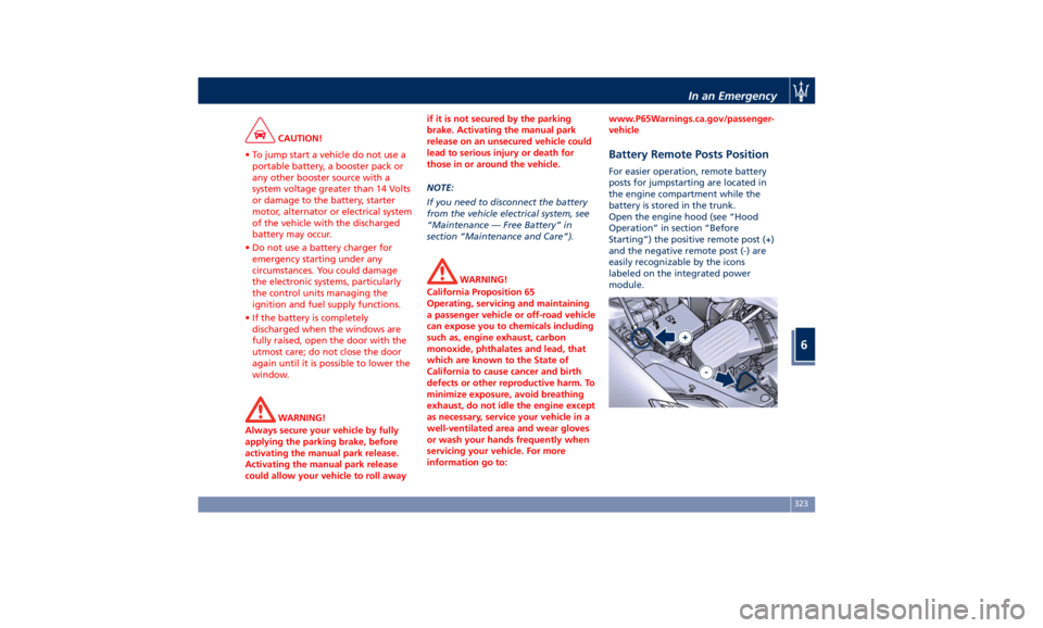
Battery Remote Posts Position For easier operation, remote battery
posts for jumpstarting are located in
the engine compartment while the
battery is stored in the trunk.
Open the engine hood (see “Hood
Operation” in section “Before
Starting”) the positive remote post (+)
and the negative remote post (-) are
easily recognizable by the icons
labeled on the integrated power
module.In an Emergency
6
323
Page 354 of 396

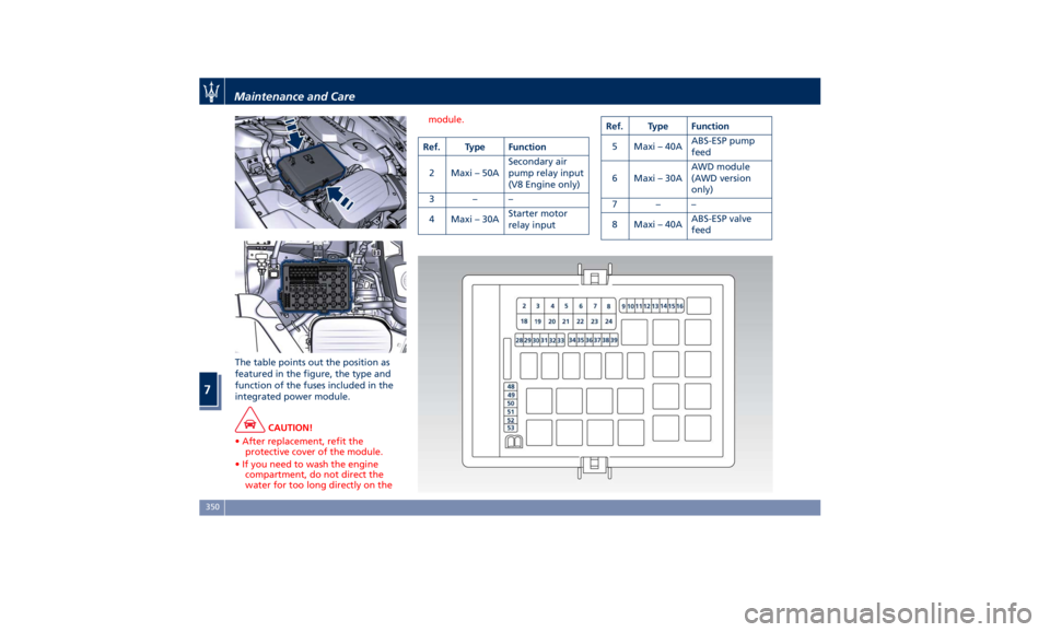
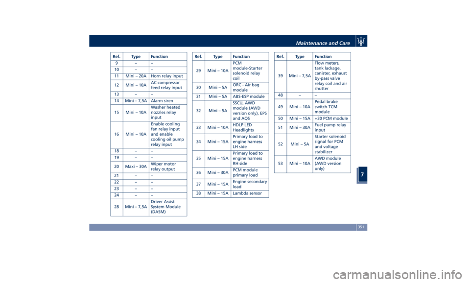
The table points out the position as
featured in the figure, the type and
function of the fuses included in the
integrated power module.
CAUTION!
• After replacement, refit the
protective cover of the module.
• If you need to wash the engine
compartment, do not direct the
water for too long directly on the module.
Ref. Type Function
2 Maxi – 50A Secondary air
pump relay input
(V8 Engine only)
3––
4 Maxi – 30A Starter motor
relay input Ref. Type Function
5 Maxi – 40A ABS-ESP pump
feed
6 Maxi – 30A AWD module
(AWD version
only)
7––
8 Maxi – 40A ABS-ESP valve
feedMaintenance and Care
7
350
Page 355 of 396

Ref. Type Function
9––
10 – –
11 Mini – 20A Horn relay input
12 Mini – 10A AC compressor
feed relay input
13 – –
14 Mini – 7,5A Alarm siren
15 Mini – 10A Washer heated
nozzles relay
input
16 Mini – 10A Enable cooling
fan relay input
and enable
cooling oil pump
relay input
18 – –
19 – –
20 Maxi – 30A Wiper motor
relay output
21 – –
22 – –
23 – –
24 – –
28 Mini – 7,5A Driver Assist
System Module
(DASM) Ref. Type Function
29 Mini – 10A PCM
module-Starter
solenoid relay
coil
30 Mini – 5A ORC - Air bag
module
31 Mini – 5A ABS-ESP module
32 Mini – 5A SSCU, AWD
module (AWD
version only), EPS
and AQS
33 Mini – 10A HDLP LED
Headlights
34 Mini – 15A Primary load to
engine harness
LH side
35 Mini – 15A Primary load to
engine harness
RH side
36 Mini – 30A PCM module
primary load
37 Mini – 15A Engine secondary
load
38 Mini – 15A Lambda sensor Ref. Type Function
39 Mini – 7,5A Flow meters,
tank lackage,
canister, exhaust
by-pass valve
relay coil and air
shutter
48 – –
49 Mini – 10A Pedal brake
switch-TCM
module
50 Mini – 15A +30 PCM module
51 Mini – 30A Fuel pump relay
input
52 Mini – 5A Starter solenoid
signal for PCM
and voltage
stabilizer
53 Mini – 10A AWD module
(AWD version
only)Maintenance and Care
7
351