heater MASERATI QUATTROPORTE 2019 Owners Manual
[x] Cancel search | Manufacturer: MASERATI, Model Year: 2019, Model line: QUATTROPORTE, Model: MASERATI QUATTROPORTE 2019Pages: 396, PDF Size: 13.9 MB
Page 103 of 396
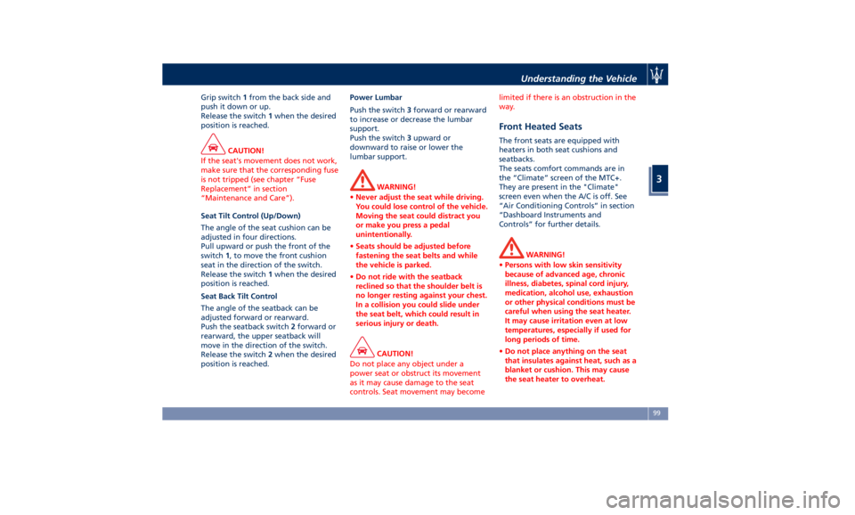
Grip switch 1 from the back side and
push it down or up.
Release the switch 1 when the desired
position is reached.
CAUTION!
If the seat's movement does not work,
make sure that the corresponding fuse
is not tripped (see chapter “Fuse
Replacement” in section
“Maintenance and Care”).
Seat Tilt Control (Up/Down)
The
angle of the seat cushion can be
adjusted in four directions.
Pull upward or push the front of the
switch 1 , to move the front cushion
seat in the direction of the switch.
Release the switch 1 when the desired
position is reached.
Seat Back Tilt Control
The angle of the seatback can be
adjusted forward or rearward.
Push the seatback switch 2 forward or
rearward, the upper seatback will
move in the direction of the switch.
Release the switch 2 when the desired
position is reached. Power Lumbar
Push the switch 3 forward or rearward
to increase or decrease the lumbar
support.
Push the switch 3 upward or
downward to raise or lower the
lumbar support.
WARNING!
• Never adjust the seat while driving.
You could lose control of the vehicle.
Moving the seat could distract you
or make you press a pedal
unintentionally.
• Seats should be adjusted before
fastening the seat belts and while
the vehicle is parked.
• Do not ride with the seatback
reclined so that the shoulder belt is
no longer resting against your chest.
In a collision you could slide under
the seat belt, which could result in
serious injury or death.
CAUTION!
Do not place any object under a
power seat or obstruct its movement
as it may cause damage to the seat
controls. Seat movement may become limited if there is an obstruction in the
way.
Front Heated Seats The front seats are equipped with
heaters in both seat cushions and
seatbacks.
The seats comfort commands are in
the “Climate” screen of the MTC+.
They are present in the "Climate"
screen even when the A/C is off. See
“Air Conditioning Controls” in section
“Dashboard Instruments and
Controls” for further details.
WARNING!
• Persons with low skin sensitivity
because of advanced age, chronic
illness, diabetes, spinal cord injury,
medication, alcohol use, exhaustion
or other physical conditions must be
careful when using the seat heater.
It may cause irritation even at low
temperatures, especially if used for
long periods of time.
• Do not place anything on the seat
that insulates against heat, such as a
blanket or cushion. This may cause
the seat heater to overheat.Understanding the Vehicle
3
99
Page 104 of 396
Front Seats Heat Function
NOTE:
The engine must be running for the
heated seats to operate.
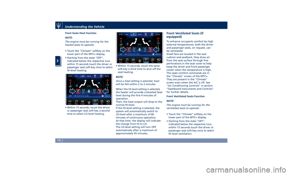
• Touch the “Climate” softkey on the
lower part of the MTC+ display.
• Starting from the state “OFF”,
indicated below the respective icon,
within 15 seconds touch the driver or
passenger seat soft-key once to select
HI-level heating.
• Within 15 seconds, touch the driver
or passenger seat soft-key a second
time to select LO-level heating. • Within 15 seconds, touch the same
soft-key a third time to shut off the
seat heating.
NOTE:
Once a heat setting is selected, heat
will be felt within 2 to 5 minutes.
When the HI-level setting is selected,
the heater will provide a boosted heat
level during the first 4 minutes of
operation.
Then, the heat output will drop to the
normal HI-level.
If the HI-level setting is selected, the
system will automatically switch to
LO-level after a maximum of 60
minutes of continuous operation.
At that time, the display will indicate
the change from HI to LO.
The LO-level setting will turn OFF
automatically after a maximum of
approximately 45 minutes. Front Ventilated Seats (if
equipped) To enhance occupants comfort by high
external temperatures, both the driver
and passenger seats, on request, can
be ventilated.
Small fans are located in the seat
cushion and seatback, they draw air
from the seat surface through fine
perforations in the seat cover to help
keep the driver and front passenger
cooler when the temperature is high.
The seats comfort commands are in
the “Climate” screen of the MTC+.
They are present in the "Climate"
screen even when the A/C is off. See
“Air Conditioning Controls” in section
“Dashboard Instruments and Controls”
for further details.
Front Ventilated Seats Function
NOTE:
The engine must be running for the
ventilated seats to operate.
• Touch the “Climate” softkey on the
lower part of the MTC+ display.
• Starting from the state “OFF”,
indicated below the respective icon,
within 15 seconds touch the driver or
passenger seat soft-key once to select
HI-level ventilation.Understanding the Vehicle
3
100
Page 108 of 396
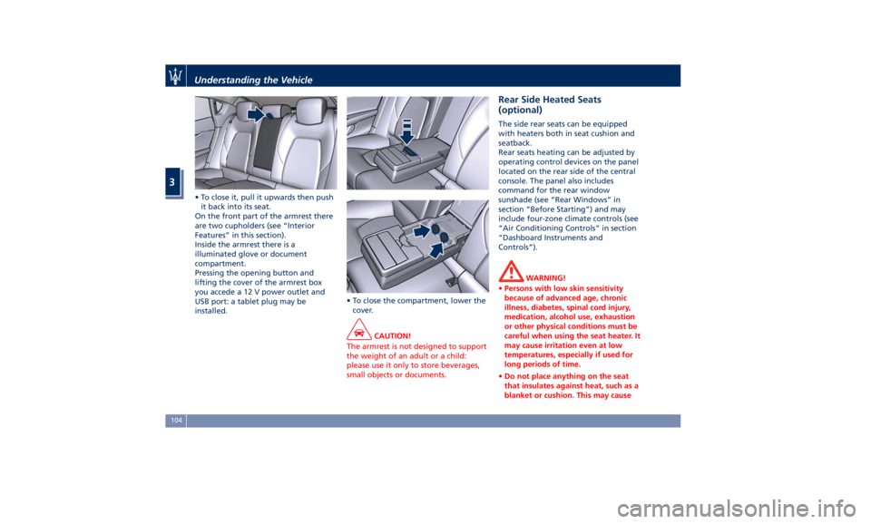
• To close it, pull it upwards then push
it back into its seat.
On the front part of the armrest there
are two cupholders (see “Interior
Features” in this section).
Inside the armrest there is a
illuminated glove or document
compartment.
Pressing the opening button and
lifting the cover of the armrest box
you accede a 12 V power outlet and
USB port: a tablet plug may be
installed. • To close the compartment, lower the
cover.
CAUTION!
The armrest is not designed to support
the weight of an adult or a child:
please use it only to store beverages,
small objects or documents. Rear Side Heated Seats
(optional) The side rear seats can be equipped
with heaters both in seat cushion and
seatback.
Rear seats heating can be adjusted by
operating control devices on the panel
located on the rear side of the central
console. The panel also includes
command for the rear window
sunshade (see “Rear Windows” in
section “Before Starting”) and may
include four-zone climate controls (see
“Air Conditioning Controls” in section
“Dashboard Instruments and
Controls”).
WARNING!
• Persons with low skin sensitivity
because of advanced age, chronic
illness, diabetes, spinal cord injury,
medication, alcohol use, exhaustion
or other physical conditions must be
careful when using the seat heater. It
may cause irritation even at low
temperatures, especially if used for
long periods of time.
• Do not place anything on the seat
that insulates against heat, such as a
blanket or cushion. This may causeUnderstanding the Vehicle
3
104
Page 109 of 396
the seat heater to overheat. Sitting
in a seat that has been overheated
could cause irritation due to the
increased surface temperature of the
seat.
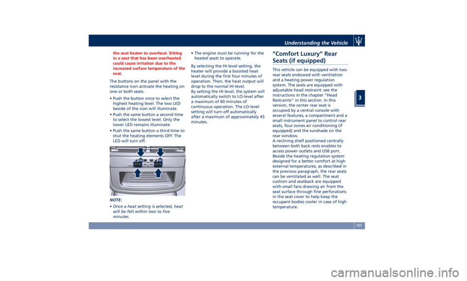
The buttons on the panel with the
resistance
icon activate the heating on
one or both seats.
• Push the button once to select the
highest heating level. The two LED
beside of the icon will illuminate.
• Push the same button a second time
to select the lowest level. Only the
lower LED remains illuminate.
• Push the same button a third time to
shut the heating elements OFF. The
LED will turn off.
NOTE:
• Once a heat setting is selected, heat
will be felt within two to five
minutes. • The engine must be running for the
heated seats to operate.
By selecting the HI-level setting, the
heater will provide a boosted heat
level during the first four minutes of
operation. Then, the heat output will
drop to the normal HI-level.
By setting the HI-level, the system will
automatically switch to LO-level after
a maximum of 60 minutes of
continuous operation. The LO-level
setting will turn off automatically
after a maximum of approximately 45
minutes.
“Comfort Luxury” Rear
Seats (if equipped) This vehicle can be equipped with two
rear seats endowed with ventilation
and a heating power regulation
system. The seats are equipped with
adjustable head restraint: see the
instructions in the chapter “Head
Restraints” in this section. In this
version, the center rear seat is
occupied by a central console with
several features, a compartment and a
small instrument panel to control rear
seats, four-zones air conditioning (if
equipped) and the sunshade on the
rear window.
A reclining shelf positioned centrally
between both back rests enables to
access power outlets and USB port.
Beside the heating regulation system
designed for a better comfort at high
external temperatures, as described in
the previous paragraph, the rear seats
can be ventilated as well. The seat
cushion and seatback are equipped
with small fans drawing air from the
seat surface through fine perforations
in the seat cover to help keep the
occupant bodies cooler in case of high
temperature.Understanding the Vehicle
3
105
Page 116 of 396
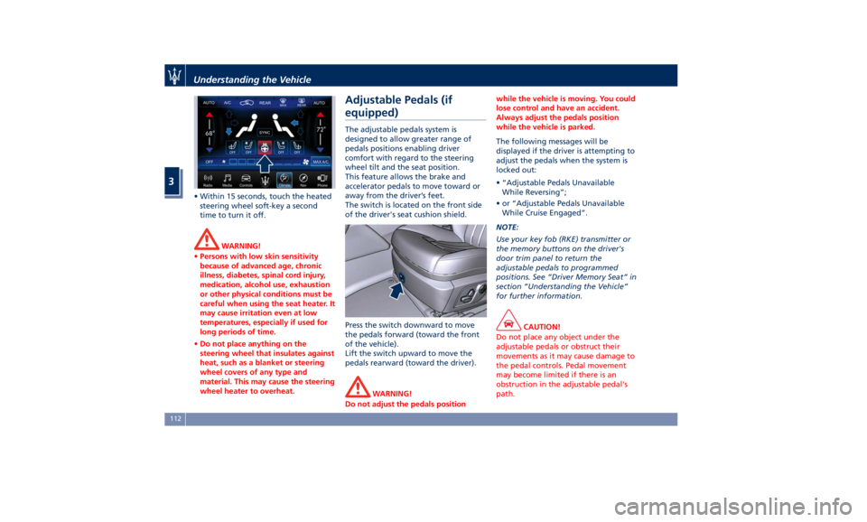
• Within 15 seconds, touch the heated
steering wheel soft-key a second
time to turn it off.
WARNING!
• Persons with low skin sensitivity
because of advanced age, chronic
illness, diabetes, spinal cord injury,
medication, alcohol use, exhaustion
or other physical conditions must be
careful when using the seat heater. It
may cause irritation even at low
temperatures, especially if used for
long periods of time.
• Do not place anything on the
steering wheel that insulates against
heat, such as a blanket or steering
wheel covers of any type and
material. This may cause the steering
wheel heater to overheat. Adjustable Pedals (if
equipped) The adjustable pedals system is
designed to allow greater range of
pedals positions enabling driver
comfort with regard to the steering
wheel tilt and the seat position.
This feature allows the brake and
accelerator pedals to move toward or
away from the driver’s feet.
The switch is located on the front side
of the driver's seat cushion shield.
Press the switch downward to move
the pedals forward (toward the front
of the vehicle).
Lift the switch upward to move the
pedals rearward (toward the driver).
WARNING!
Do not adjust the pedals position while the vehicle is moving. You could
lose control and have an accident.
Always adjust the pedals position
while the vehicle is parked.
The following messages will be
displayed
if the
driver is attempting to
adjust the pedals when the system is
locked out:
• “Adjustable Pedals Unavailable
While Reversing”;
• or “Adjustable Pedals Unavailable
While Cruise Engaged”.
NOTE:
Use your key fob (RKE) transmitter or
the memory buttons on the driver's
door trim panel to return the
adjustable pedals to programmed
positions. See “Driver Memory Seat” in
section “Understanding the Vehicle”
for further information.
CAUTION!
Do not place any object under the
adjustable pedals or obstruct their
movements as it may cause damage to
the pedal controls. Pedal movement
may become limited if there is an
obstruction in the adjustable pedal's
path.Understanding the Vehicle
3
112
Page 328 of 396
Jump-Start Procedure WARNING!
• Stay clear of the radiator cooling fan
whenever the engine hood is raised.
It can start anytime the ignition
switch is on. You could be injured by
the moving fan blades.
• Remove any metal jewelry such as
watch bands or bracelets that might
make an inadvertent electrical
contact. You could be seriously
injured.
• Do not allow the vehicles involved in
the jumpstarting operation to touch
each other as this could establish a
ground connection and cause
personal injury.
• Turn off the heater, radio, and all
unnecessary
electrical accessories.
•
Set the parking brake, shift the
automatic transmission into P (Park)
and turn the ignition to OFF .
• If using another vehicle to jumpstart
the battery, park the vehicle within
the jumper cables reach and set the
parking brake and make sure the
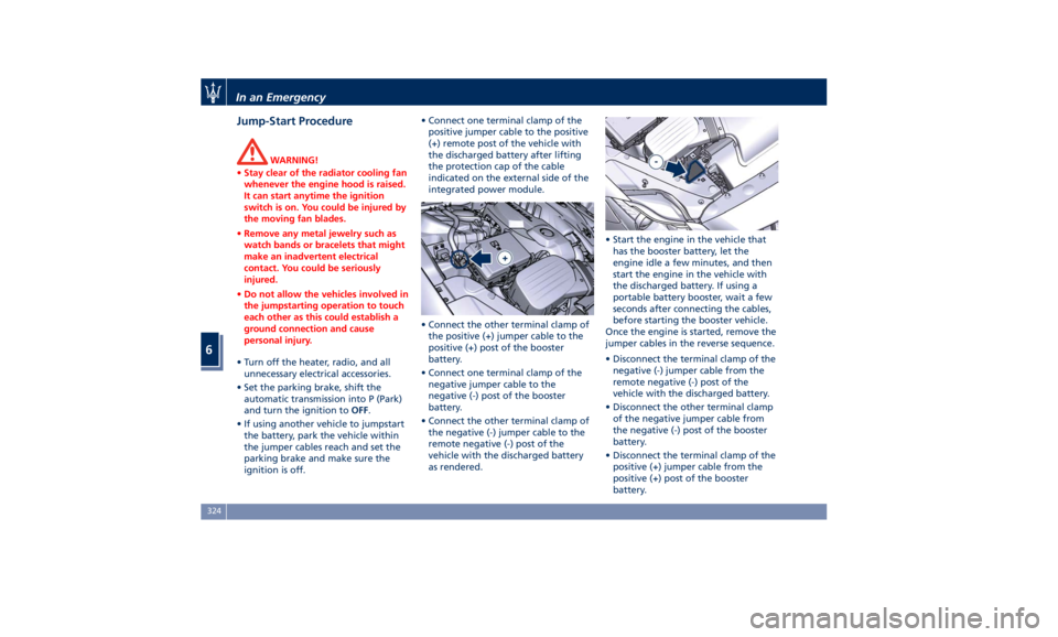
ignition is off. • Connect one terminal clamp of the
positive jumper cable to the positive
(+) remote post of the vehicle with
the discharged battery after lifting
the protection cap of the cable
indicated on the external side of the
integrated power module.
• Connect the other terminal clamp of
the positive (+) jumper cable to the
positive (+) post of the booster
battery.
• Connect one terminal clamp of the
negative jumper cable to the
negative (-) post of the booster
battery.
• Connect the other terminal clamp of
the negative (-) jumper cable to the
remote negative (-) post of the
vehicle with the discharged battery
as rendered. • Start the engine in the vehicle that
has the booster battery, let the
engine idle a few minutes, and then
start the engine in the vehicle with
the discharged battery. If using a
portable battery booster, wait a few
seconds after connecting the cables,
before starting the booster vehicle.
Once the engine is started, remove the
jumper cables in the reverse sequence.
• Disconnect the terminal clamp of the
negative (-) jumper cable from the
remote negative (-) post of the
vehicle with the discharged battery.
• Disconnect the other terminal clamp
of the negative jumper cable from
the negative (-) post of the booster
battery.
• Disconnect the terminal clamp of the
positive (+) jumper cable from the
positive (+) post of the booster
battery.In an Emergency
6
324
Page 357 of 396
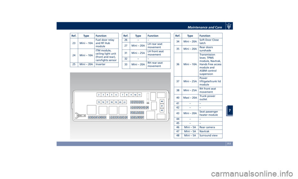
Ref. Type Function
23 Mini – 10A Fuel door relay
and RF Hub
module
24 Mini – 10A ITM module,
ceiling light unit
(front and rear),
rain/lights sensor
25 Mini – 20A Inverter Ref. Type Function
26 – –
27 Mini – 20A LH rear seat
movement
31 Mini – 25A LH front seat
movement
32 – –
33 Mini – 20A RH rear seat
movement Ref. Type Function
34 Mini – 20A Soft Door Close
latch
35 Mini – 20A Rear doors
sunshade
36 Mini – 10A Transmission
lever, TPMS
module, Navtrak,
Hands Free access
module and
ASBM control
suspension
37 Mini – 25A Power
liftigate/trunk lid
module
38 Mini – 25A RH front seat
movement
40 Maxi – 20A Trunk power
outlet
41 – –
42 – –
43 Mini – 20A Seat passenger
heater module
44 – –
45 – –
46 Mini – 5A Rear camera
47 Mini – 5A Navtrak
48 Mini – 5A Surround viewMaintenance and Care
7
353
Page 358 of 396
Ref. Type Function
49 Mini – 10A Internal
temperature
sensor, internal
mirror and HALF
50 – –
51 Mini – 25A Rear seat and
steering wheel
heater module
52 – –
53 Mini – 25A Rear seat vented
module
54 Mini – 7,5A Blind Spot
module
55 – –
56 Mini – 7,5A Blower front
HVAC coil relay
57 Mini – 7,5A Blower rear
HVAC coil relay
58 – –
59 Mini – 10A SDC module,
transmission
lever, ASBM, rear
tunnel stack
switch
60 Mini – 10A SDC module Ref. Type Function
61 Mini – 25A Front console
power outlet and
cigar lighter
62 Mini – 7,5A Front HVAC
module
63 Mini – 20A Blower rear
HVAC
64 Mini – 10A Wi-fi, rear HVAC
module
65 Mini – 10A Intelligent
battery sensor
66 Mini – 10A Wi-fi, RSE
67 Mini – 7,5A USB charge
outlet, sunroof
68 Mini – 20A Rear sunshade
module
69 Mini – 25A Rear console
power outlet and
cigar lighter
70 Mini – 10A Front HVAC
module and
Parking Aid
Module (PAM)Fuse Box under the Dashboard This box is located in an internal area
that can be accessed only by removing
the glove compartment on the
dashboard left side. Considering the
complexity of this operation, we
recommend having the fuses replaced
by an Authorized Maserati Dealer .
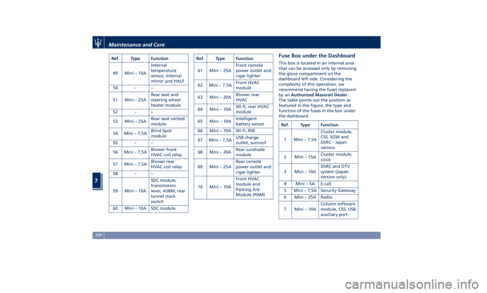
The table points out the position as
featured in the figure, the type and
function of the fuses in the box under
the dashboard.
Ref. Type Function
1 Mini – 7,5A Cluster module,
CSS, SGW and
DSRC - Japan
version
2 Mini – 15A Cluster module,
clock
3 Mini – 10A DSRC and DTV
system (Japan
version only)
4 Mini – 5A E-call
5 Mini – 7,5A Security Gateway
6 Mini – 25A Radio
7 Mini – 10A Column software
module, CSS, USB
auxiliary portMaintenance and Care
7
354