coolant MAZDA 232 1990 Suplement User Guide
[x] Cancel search | Manufacturer: MAZDA, Model Year: 1990, Model line: 232, Model: MAZDA 232 1990Pages: 677, PDF Size: 61.19 MB
Page 85 of 677

B2 INSTALLATION
93GOB2-74 1
93GOB2-743
82-32
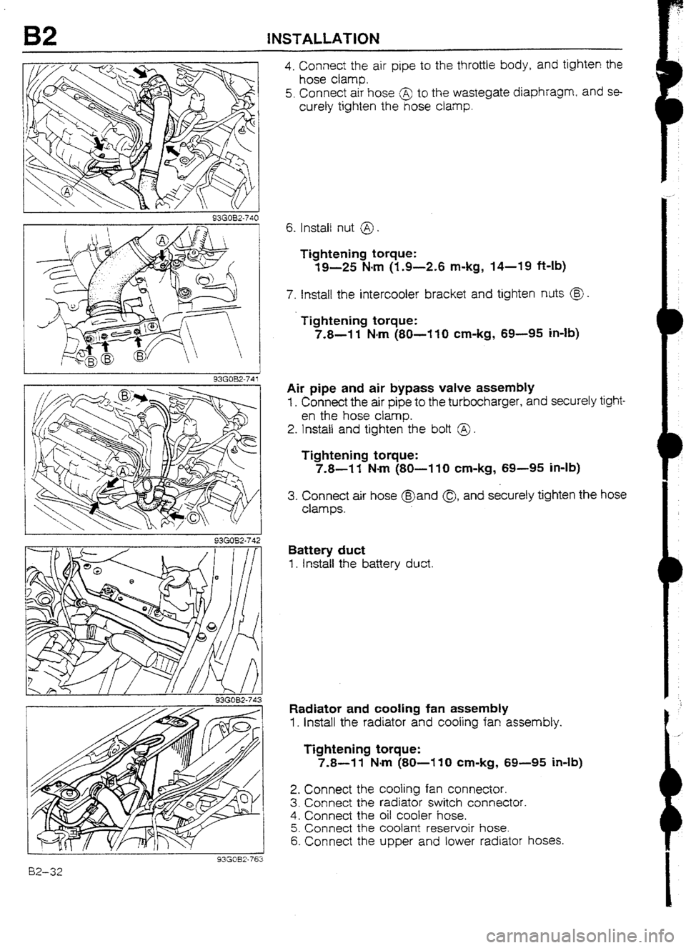
4. Connect the air pipe to the throttle body, and tighten the
hose clamp.
5. Connect air hose @ to the wastegate diaphragm,
and se-
curely tighten the hose clamp.
6. Install nut @
Tightening torque:
19-25 Narn (1.9-2.6 m-kg, 14-19 ft-lb)
7. Install the intercooter bracket and tighten nuts @J .
Tightening torque:
7.8-l 1 Narn (80-I IO cm-kg, 69-95 in-lb)
Air pipe and air bypass valve assembly
1. Connect the air pipe to the turbocharger, and securely tight-
en the hose clamp.
2. Install and tighten the bolt @ .
Tightening torque:
7.8-l 1 Nom (80-I 10 cm-kg, 69-95 in-ib)
3. Connect air hose @and Q1 and securely tighten the hose
clamps.
Battery duct
1. install the battery duct.
Radiator and tooting fan assembly
1. Install the radiator and cooling fan assembly.
Tightening torque:
7.8-l 1 Nm (80-l 10 cm-kg, 69-95 Mb)
2. Connect the tooting fan connector.
3. Connect the radiator switch connector.
4. Connect the oil cooler hose.
5. Connect the coolant reservoir hose.
6. Connect the upper and lower radiator hoses.
Page 87 of 677

82 INSTALLATION
Steps after installation
1. If the engine oil was drained, refill with the specified amount and type of engine oil.
2. Fill the radiator with the specified amount and type of engine coolant.
3. Fill the transaxie with the specified amount and type of transaxle oil. (Refer to page J3-36.)
4. Connect the negative battery cable.
5. Start the engine and check the following:
(I) Engine oiI, transaxle oil, and engine coolant for leakage
(2) Ignition timing and idle speed
(3) Operation of emission control system
6. Perform a road test.
7. Recheck the engine oil and engine coolant levels.
93G032-747
-
BZ-34
Page 90 of 677

E
COOLING SYSTEM
1NDEX . ..*....*~.....*..*~~**~=~~.~~.~...~..**.~.....*...~.. E- 2
OUTLINE .................................................. E- 4
OUTLlNE OF CONSTRUCTION.. ................ E- 4
COOLANT FLOW CHART.. ....................... E- 4
SPECIFICATKINS
.................................... E- 5
TWO-STAGE THERMOSTAT.. .................... E- 6
RADIATOR AND COOLING FAN.. .............. E- 7
ELECTRIC COOLING FAN SYSTEM ........... E- 8
SUPPLEMENTAL SERVICE INFORMATION E- 9
THERMOSTAT
.......................................... E- 9
INSPECTION
.......................................... E- 9
ELECTRIC COOLING FAN SYSTEM ............ E-l 0
SYSTEM INSPECTlON
.............................. E-l 0
FAN MOTOR
............................................. E-If
iNSPECTION .......................................... E-l 1
WATER THERMOSWITCH
.......................... E-l I
INSPECTION .......................................... E-f 1
RADIATOR THERMOSWITCH
..................... E-l 2
REMOVAL I INSPECTION I INSTALLATION.. E-12
FAN RELAY .............................................. E-l 3
REMOVAL I tNSPECTlUN .......................... E-l 3
93GOEX-701
Page 91 of 677

E tNDEX
INDEX
-
- &ANT RESERVOlR
ENGiNE COOLANT
TOTAL CAPACITY
MTX: 5.0 liters (5.3 US qt, 4.4 Imp qt)
ATX: 6.0 liters (6.3 US qt. 5.3
tmp qt)
1. Fan motor
Inspection .._.....,._............._..........
page E-1 I
E-Z
Page 93 of 677

E OUTLINE
OUTLINE
OUTttNE OF CONSTRUCTION
The cooling system in the 323 4WD model is basically the same as in the 323 2WD model.
Although there is no fundamental change from the BP DOHC of the 2WD model, the coolant circulation
path has been changed to direct coolant to the water-cooied turbocharger.
A two-stage thermostat is used in the BP DUHC turbocharged engine to stabilize the engine coolant tem-
peratu re.
The radiator and cooling fan specifications are different. The BP DOHC turbocharged engine of the 4WD
model uses a two-speed electric cooling fan.
93GOEX-704
COOLANT FLOW CHART (BP DOHC TURBO)
E-4
Page 94 of 677
![MAZDA 232 1990 Suplement User Guide SPECIFICATlONS
-
km
Cootlng system
Coolant camacltv
EnginelTtansaxte
lrters [US Qt. Imo at)
8P SOHC ] 8P DOW Turbo
MTX ATX
I MTX
Water-cooled, forced crrculation
5.0 (5.3, 4.4)
I 6.0 t&3,5 MAZDA 232 1990 Suplement User Guide SPECIFICATlONS
-
km
Cootlng system
Coolant camacltv
EnginelTtansaxte
lrters [US Qt. Imo at)
8P SOHC ] 8P DOW Turbo
MTX ATX
I MTX
Water-cooled, forced crrculation
5.0 (5.3, 4.4)
I 6.0 t&3,5](/img/28/57056/w960_57056-93.png)
SPECIFICATlONS
-
km
Cootlng system
Coolant camacltv
EnginelTtansaxte
lrters [US Qt. Imo at)
8P SOHC ] 8P DOW Turbo
MTX ATX
I MTX
Water-cooled, forced crrculation
5.0 (5.3, 4.4)
I 6.0 t&3,5.3) -
1 Type
Water puma 1
I Water seal Centrifugal
Unified mechanical
seal
: Type I Wax,single stage”‘, Wax, two-stage*’ 1 Wax, two-stage
80.5-83.5 (177-182)“1
Opening temperature
“C (OF)
Main: 86.5-89.5 (188-l 93) *’ Main: 86.5-89.5 (lSS--193)
The:mosta! 1 Sub : 83.5-86.5 (182-188) Sub 83.G86.5 (182-188)
1 Full-open temperature OC
(OF) 95 (203)*‘, 100 (212)*’ i 100 (212)
L I
“...Except cold area, *2...Cotd area only
1 r 1 93GOEX-706 j Full-open lift mm (in) 8.5 (0.335) or more’l
Main: 8.0 (0.31).mln.‘2
Sub : 1.5 10.061 min * Main: 8.0 (0.31) min.
Sub : I.5 (0.06) mm.
Radiator 1 Type
Cap vaive opening-pressure ’
kPa (kglcm2, psi) Corrugated fin
74-l 03 (0.75-I .05, 11-l 5) j Tvm?
EIectnc I
Coohg fan f Outer drameter mm (in) 320 (12.6) 340 (13.4)
Blade
Number 4 5
Motor
/ Current A
6.6 * 1 Hi : 13.3 + 10% max.
Lo: 8.8 + 10% max. E-5
Page 95 of 677

E OUTlANE
TWO-STAGE THERMOSTAT (BP DOHC TURBO)
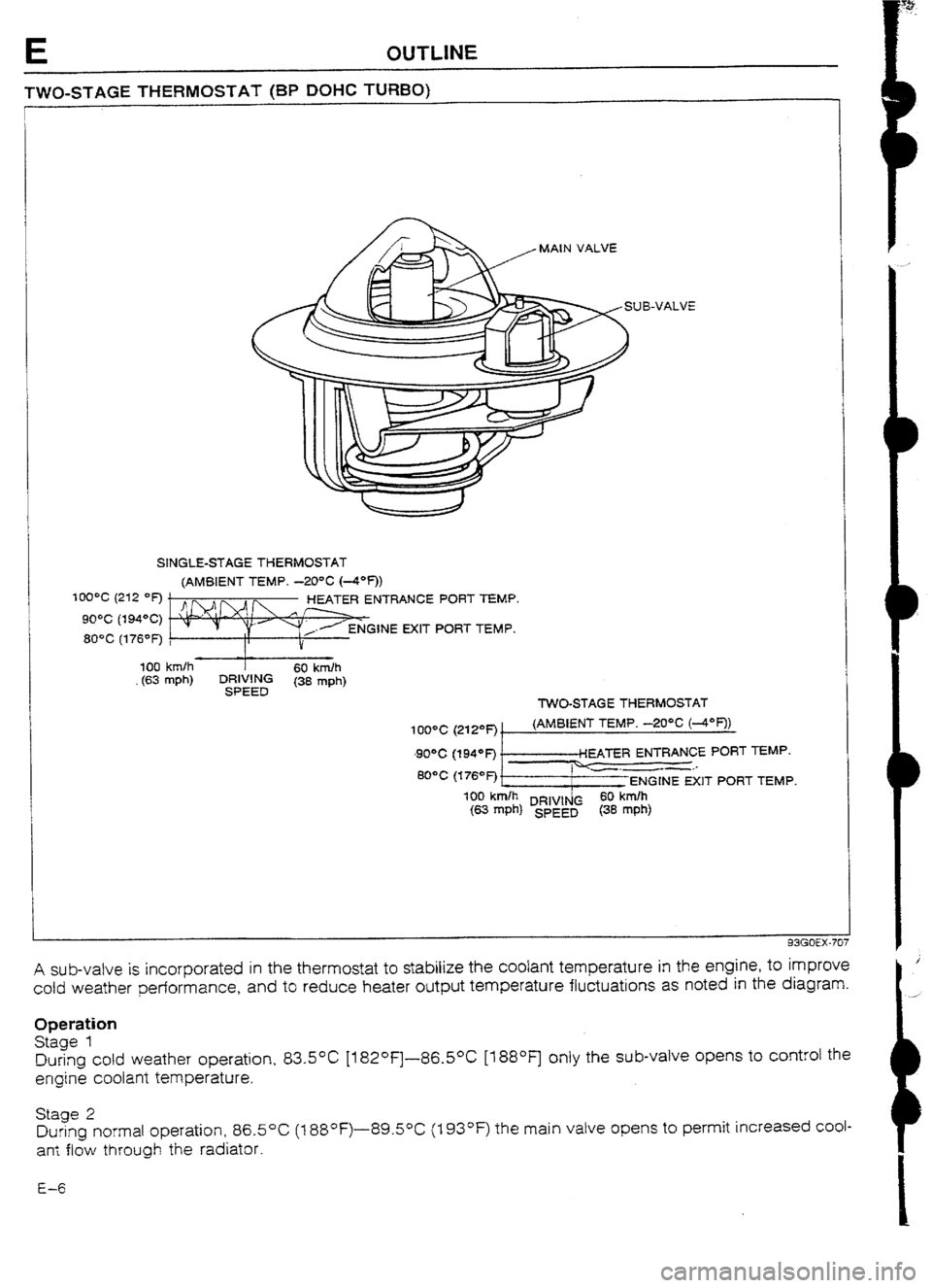
MAIN VALVE
SINGLE-STAGE THERMOSTAT
(AMBIENT fEMP. -20% (4*f))
NTRANCE PORT TEMP
GINE EXIT PORT TEMP.
- 100 km/h
60 kndh
(63 mph) ~~~~~ (38 mph)
TWO-STAGE THERMOSTAT
A sub-valve is incorporated in the thermostat to stabilize the coolant temperature in the engine, to improve
cold weather performance, and to reduce heater output temperature fluctuations as noted in the diagram.
Operation
Stage 1
During cold weather operation, 83.5*C [182°F]-86.50C [t 88OF] only the sub-valve opens to control the
engine coolant temperature.
Stage 2
During normal operation, 86.5OC (1 88°F)-89.50C (I 93OF) the main valve opens to permit increased coul-
an: flow through the radiator.
E-6
Page 97 of 677

E OUTLINE
ELECTRIC COCUNG FAN SYSTEM (BP DOHC TURBO)
System Circuit
I I
WITH A/C
r----‘-- -___- ---------.--------;
ADDITIONAL
FAN
MOTOR
I
II 1 A/C RELAY
RAD1ATdTHERMOSWITCH
ABOVE 105% I221 OF-): ON +IIAGNOSlS
CONNECTOR
WATER
THERMOSWlTCH
ABOVE 97% (207OF): ON
Operation 1. When the coolant temperature exceeds 97OC (207*F), the water thermoswitch turns ON to close the No.7
relay, and connects the + I and -1 terminals of the fan motor
connector. The fan motor turns at low
speed (about 1,660 rpm).
2. When the coolant temperature exceeds 105OC (221 OF), the radiator thermoswitch turns ON, to close the
No.2 and No.3 relays, and connects
the +2 and -2 terminals of the fan motor connector. The fan mo-
tor turns at high speed (about 2,200 rpm).
3. if the vehicle is equipped with air conditioning, the cooling fan motor operates whenever the
NC switch
and the blower switch are on, regardless of
the coolant temperature. Also, when the A/C switch and the blower switch are on, the A/C retay closes
to operate the additional fan
motur.
Note
l The water thermoswitch and the cooling fan reIay are normally-open switches.
Checking cooling fan operation 1. Jump across the TFA and the GND terminals
of the diagnosis connector with a jumper wire.
2. Turn the ignition switch to ON and verify that the cooling fan operates smoothly.
Note
l When the water thermoswitch connector is disconnected, the cooling fan wiif not operate.
E-8
Page 99 of 677

E ELECTRIC COOLING FAN SYSTEM
ELECTRIC COOLING FAN SYSTEM (BP
DUHC TURBO)
SYSTEM ClRCUIT
r
WITH A/C
r-- _______ ------
I ADDITIONAL
1 FAN
I PRESSL
SWITCH
I WATER
THERMOSWfTCtl
ABOVE 87OC (207OF): ON
RADlATOjl THERMOSWITCH
ABOVE 105*C (221 “I=): ON
8 93GOEX-719
-
%
J--- QY- -THERMOME?ERsi-=i
--
--------L-
93GOEX-7 i 2
E-10 SYSTEM INSPECTION
1. Jump across the test fan (TFA) terminal and the ground
(GN D) terminal of the diagnosis connector.
2. Turn the ignition switch ON and verify that the fan operates.
If the fan does not operate, inspect the cooling fan system
components and wiring harness.
3. Remove the radiator cap and place a thermometer in the
radiator filler neck.
4. Start the engine.
5. Verify that the fan operates when the coolant temperature
reaches approx. 97*C (207°F).
If it does, check the water thermoswitch.
(Refer to page
E--i I.)
Page 100 of 677

FAN MOTOR, WATER THERMOSWITCH E
93GOEX-71:
93GOEX-714
93GOEX-720
tNSPECTlON
Single-speed Type (For BP SOW MTX)
I. Verify
that the battery is fully charged.
2. Disconnect the fan motor connector.
3. Connect the battery and an ammeter to the fan motor
con-
nector.
4. Verify that current is as specified.
Current (A): 6.6 k 1
5. If current is not within specification and/or the fan does not
turn smoothly, replace the fan motor.
Two-speed Type (Except BP SUHC MTX)
I. Verify that the battery is fully charged.
2. Disconnect the fan motor connector.
3. Connect the battery and an ammeter to the fan motor con-
nectors for low-speed inspection.
4. Verify that the fan motor operates smoothly at the standard
cu vent.
Current (A): 8.8 + 10% max.
5. Connect the battery, an ammeter, and switch to the fan mo-
tor connectors for high-speed inspection.
6. Verify that the fan motor operates smoothly
at the standard
current or less with the switch ON.
Current (A): 13.3 + 10% max.
7. If not as specified, replace the fan motor.
WATER THERMOSWITCH
(BP DOHC TURBO)
INSPECTlUN
I . Place the switch and a thermometer in water.
2. Heat the water gradually and check continuity of the switch
with an ohmmeter.
Coolant temperature OC (OF) 1 Contrdy
I
More than 97 (207) Yes
Less than 90 (194)
NO
3. If not as specified, replace the water thermoswitch.
93GOEX.715