air filter MAZDA 232 1990 Workshop Manual Suplement
[x] Cancel search | Manufacturer: MAZDA, Model Year: 1990, Model line: 232, Model: MAZDA 232 1990Pages: 677, PDF Size: 61.19 MB
Page 23 of 677
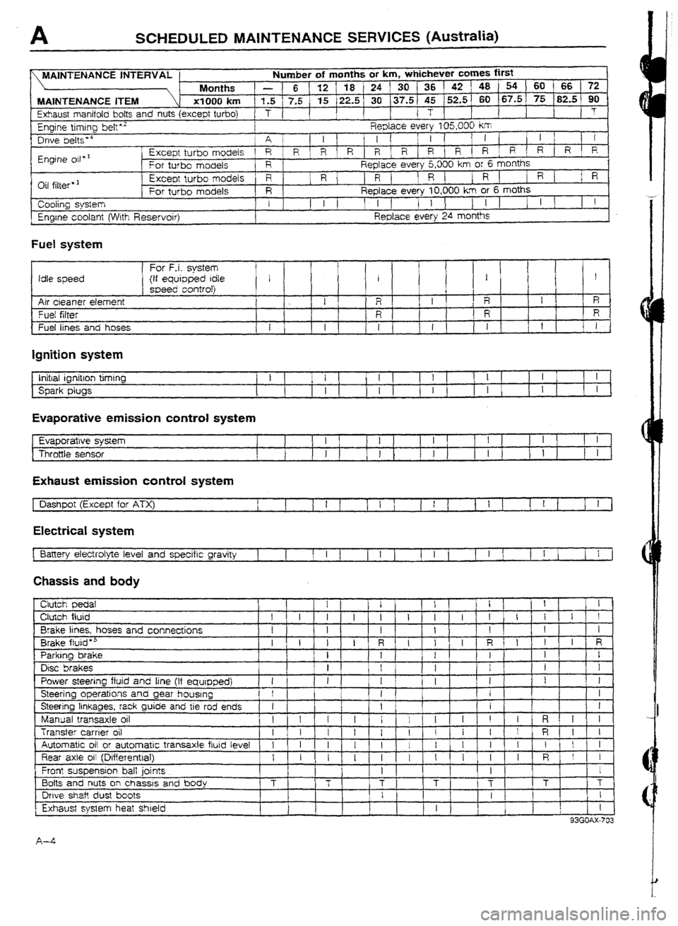
A SCHEDULED MAINTENANCE SERVICES (Australia)
lumber of months or km, whichever cumes first
P
_ 48 54 60 1 66 72
5
60 67.5 75 90 .--- .-- -
.-m-w --v-w _ _ -_-- - - _ _ - -
_ -- - - --- __-
_-
-- -- (82.5
Exhaust manifold bolts and nuts (except turbo) T 1
I i T 1
1 T
Engine timlrtg belt”’ Replace every 105,000 km
Drwe belts * a
A I 1 I 1 1 I 1
! ’ I I 1 1
Engine oil * ’ Except turbo models 1 RIR\R/RIRIRIR R R,R R R/R
For turbo models R
Replace every 5,000 km or 6 months
r-k:1 c:t+*-* 1 Except turbo models
R 1 R 1 1 R ( ) R ( 1 R ( 1
R 1 f R
-
1 VII IIIIc;I 1 For turbo models I R 1 ReDlace everv IO.000 km or E
Engine coolant (Wrth Reservoir)
Fuel
system
Replace e&y 24 months
For F-i. system
Idle speed (if equipped Idle 1 1 1 I
I speed controf)
Air cleaner element 1
R , I R I R
Fuet filter
I I? R R
~ Fuel lines and hoses
1 I 1 I I 1 I I 1 1
Ignition system
t Initial ignition timing
Spark plugs i I I I -1 I I
I I I I I
f
Evaporative emission control system
Evaporative system
Throttle sensor
Exhaust emission contra! system
[ Dashpot
(Except for ATX) I 1 I
1 1 I 1 1 t 1 1 1 1 1 ! 1 1 I 1
Electrical system
Battery electrolyte level and specific gravity ]
I 1 1 I 1 t I ’ 1 1 I 1 f I ( 1
I 1
Chassis and body
Brake lines, hoses and connections
Brake fluid * a
Parking brake
Disc brakes
1 Power steering fluid and line Ilf &uiDDedl
I 1 1 I I I
I 1 1 III II
I ’
I I
Steering operations and gear housing
I
1 1 I --r--j- 1 I
I
Steerino linkanes. rack auide and tie rod pnds .-- --
----.“.a ..‘-~--, J- -.-- _.- .-- -..-- I I I t I 1 1 I I I I I I I 1
Manual transaxle oil I \\!‘I rl\jl I 1 I R III
1 Transfer Automatic carrier oil or 09 automatic transaxle fluid level
1 1 I 1 111 I 1 I l 1 I 1 I 1[11i t I 1 I 1 I I 1 I
R 1 Iii 1 I
1 Rear axle oil (Differential) 1 t I I I I I I I I
t ’ I r . ’ 1 . I I I I I R I 1
I
I I
i T
1 T T T 1 T [ T I 1 T
Front suspension ball joints
Bolts and nuts on chassis and body
I I I . I ! ,
I 1 I . I 1 ’ I I ’
Drive shaft dust boots
I
I 1 I 1
I 1 1 I
~~
- - ’ C1utcl-1 pedat
Clutch fluid
1
A-4
Page 24 of 677
!
i
i
I
i
t-
I
i
i
e
-1
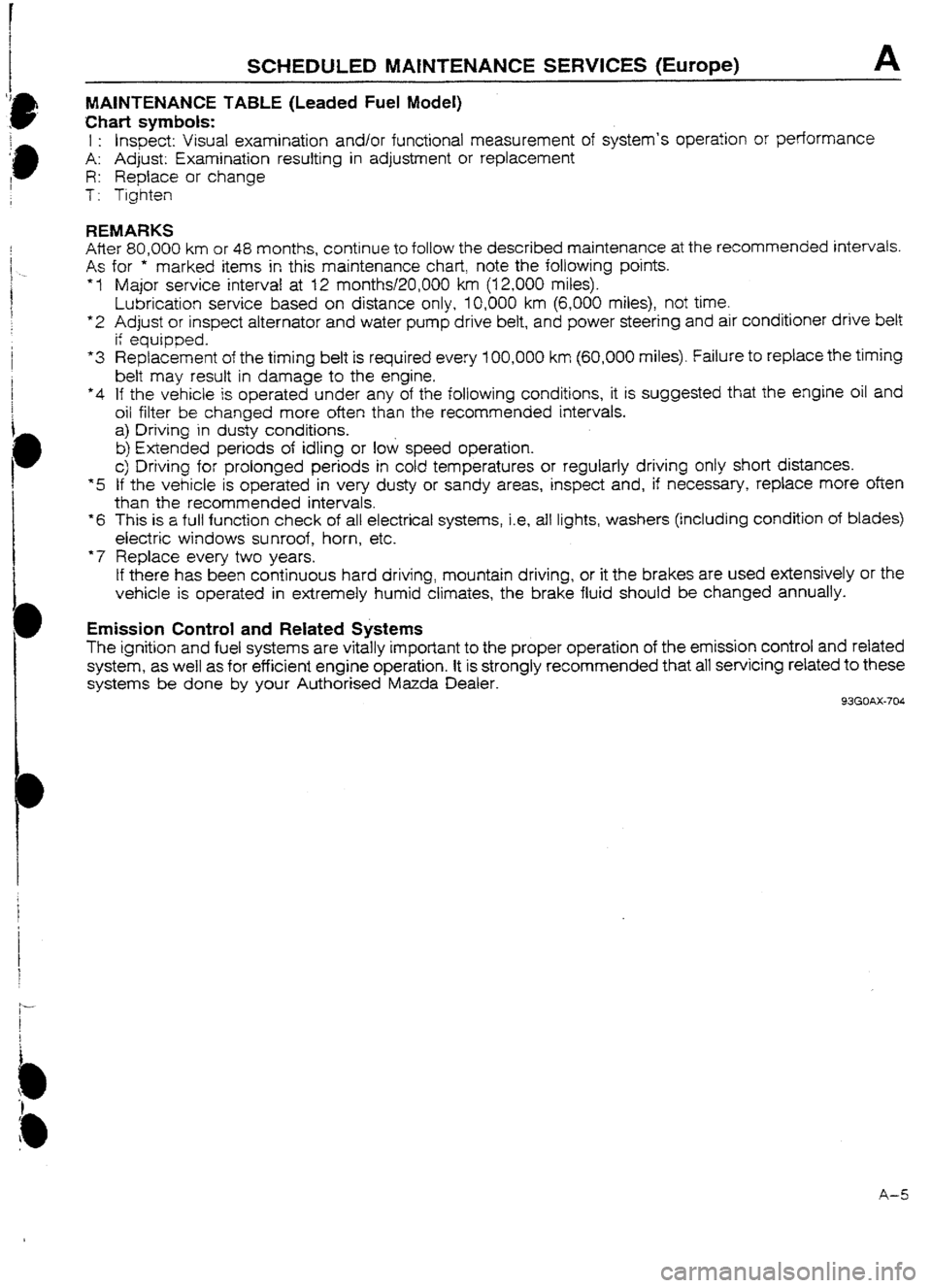
SCHEDULED MAfNTENANCE SERVICES (Europe) A
MAINTENANCE TABLE (Leaded Fuel Model)
Chart symbols:
1 : Inspect: Visual examination and/or functional measurement of system’s operation or performance
A: Adjust: Examination resulting in adjustment or replacement
R: Replace or change
T: Tighten
REMARKS
After 80.000 km or 48 months, continue to foltow the described maintenance at the recommended intervals.
As
*I
*2
“3
*4
*5
*6
*7 for *’
marked items in this’ maintenance chart, note the following points.
Major service interval at 12 months!ZO,OOO km (I 2,000 miles).
Lubrication service based on distance only, 10,000 km (6,000 miles), not time.
Adjust or inspect alternator and water pump drive belt, and power steering and air conditioner drive belt
ii equipped.
Replacement of the timing belt is required every ICQOUO km (60,000 miles). Failure to replace the timing
belt may result in damage to the engine.
If the vehicle is operated under any of the following conditions, it is suggested that the engine
oil and
oil filter be changed more often than the recommended intervals.
a) Driving in dusty conditions.
b) Extended periods of idling or low speed operation.
c) Driving for prolonged periods in cold temperatures or regularly driving only short distances.
If the vehicle is operated in very dusty or sandy areas, inspect and, if necessary, replace more often
than the recommended intervals.
This is a full function check of all electrical systems, i.e, afl lights, washers (inctuding condition of blades)
electric windows sunroof, horn, etc.
Replace every two years.
tf there has been continuous hard driving, mountain driving, or it the brakes are used extensively or the
vehicle is operated in extremely humid climates, the brake fluid should be changed annually.
Emission Control and Related Systems
The ignition and fuel systems are vitally important to the proper operation of the emission control and related
system, as well as for efficient engine operation. It is strongly recommended that all servicing related to these
systems be done by your Authorised Mazda Dealer.
93GOAX-704
A-5
Page 25 of 677
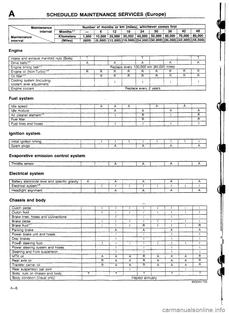
SCHEDULED MAlNTENANCE SERVICES (Europe)
Maintenance Number of months or km (miles), whichever comes first
Months” - 6 1 12 18 24 1 30
36 1 42 48
Maintenance Wometers 1,000 10,000 20,000 30,000 40,000 50,000 60,000 1 70,000 80,000
interval
(Miles) (600) (6,000) (12,000) (18,000) (24,000) (30,000) (36,000)~(42,000) (48,000)
Engine Intake
and exhaust manifold nuts (Bolts) Drive belts * 2
Engine ttming belt *’
Engine oi; (Non-Turboj’4
Oil filter * 4
Cooling system (Including coolant
level adjustment)
Enaine coolant T
1 1 1
1 1 ’
A
[ A I A 1 A ] [ A
Replace every t 00,000 km (60,000 miles)
R
R R R R R R R 1 R
R R R R R R R R
I I 1 I
Reolace everv 2 Years
Fuel system
Idle speed
Idle mixture
Air cleaner element *’ Fuel
filter
Fuel lines and hoses
I A I * A 1 A 1 A
I
A A A A
I R I R
R
I R I
1 I
t I 1 [ I
Ignition system
Initial ignition timing
Spark plugs I t I I 1 I 1 I
A A ( A A
Evaporative emission control system
Electrical system
Ejattery electrolyte level and specific gravity A
A 1 A A 1 A
Electrical system
l 6
I I I
I t I 1 I I
Headlight algnment
A A f A 1 A
Chassis and body
Clutch pedal
Clutch fluid
Brake lines, hoses and connections
Brake pedal
Brake flutd *7
Parking brake
Power brake unit and hoses
DGC brakes
Pow& steering fluid
Power steering system and hoses
Steering and front suspension
MTX oil
Rear axle oil
Transfer carrier
ui!
Rear suspension bail joint
Bolts, nuts on chassis and body
8ody condltlon (Visual onty)
-
I I I I I I I I
1 I I I I I I I
I
1 I I
i
1 I I I I I I
I I I
R I 1 I R
A A A 1 A
1
1 i 1 I
I
I I
I
I
I I I I I I I
I 1 I I
I 1 I 1 i
1 A
A R A A A R
iR,i A R A A A R
R ’
A . A R A A A R
f I
T
T T T
T
I Inspect annually
93GOAX-705
A-6
Page 27 of 677
A SCHEDULED MAINTENANCE sERvw3 (Europe)
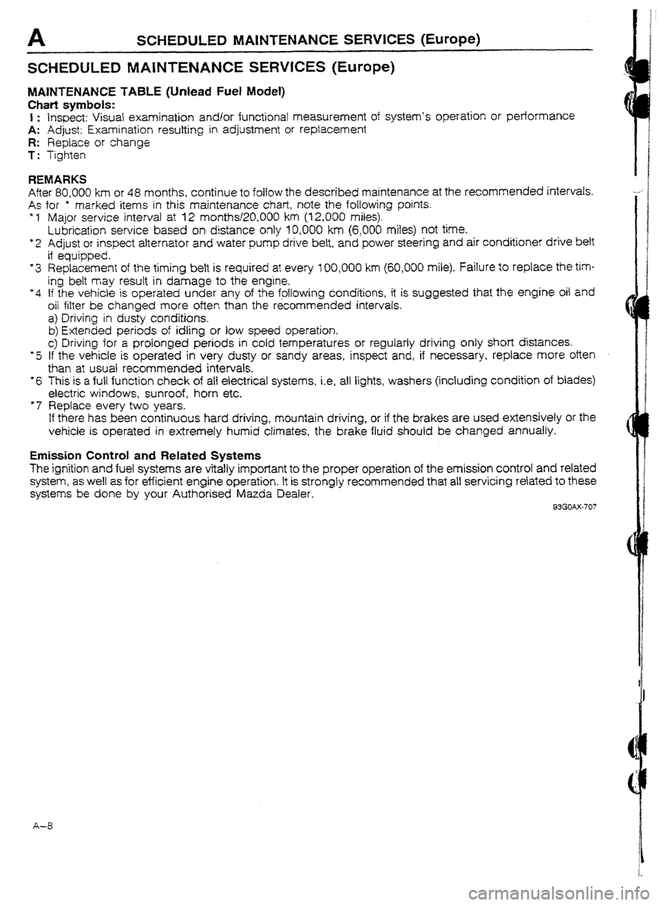
SCHEDULED MAfNTENANCE SERWCES (Europe)
MAWTENAN CE TABLE (Unlead Fuel Model)
Chati symbols:
I : Inspect: Visual examination and/or functional measurement of system’s operation or performance
A: Adjust: Examination resulting in adjustment or replacement
R: Replace or change
T: Tighten
REMARKS
After 80,000 km or 48 months, continue to follow the described maintenance at the recommended intervals.
As for * marked items in this maintenance chart, note the following points.
* 1 Major service interval at 12 months120,OOO km (12,000 miles).
Lubrication service based on distance only 10,000 km (6,000 miles) not time.
*2 Adjust or inspect alternator and water pump drive belt, and power steering and air conditioner drive belt
if equipped.
“3 Replacement of the timing belt is required at every 100,000 km (60,000 mile). failure to replace the tim-
ing belt may result in damage to the engine.
“4 If the vehicle is operated under any of the following conditions, it is suggested that the engine oil and
oil filter be changed more often than the &commended intervals.
a) Driving in dusty conditions.
b) Extended periods of idling or low speed operation.
c> Driving for a prolonged periods in cold temperatures or regularly driving only short distances.
*5 If the vehicle is operated in very dusty or sandy areas, inspect and, if necessary, replace more oten
than at usual recommended intervals.
*6 This is a full function check of all electrical systems, i.e, all lights, washers (including condition of blades)
electric windows, sunroof, horn etc.
“7 Replace every two years.
If there has been continuous hard driving, mountain driving, or if the brakes are used extensively or the
vehicle is operated in extremely humid climates, the brake fluid should be changed annually.
Emission Control and Related Systems
The ignition and fuel systems are vitally important to the proper operation of the emission control and related
system, as well as for efficient engine operation. It is strongly recommended that all servicing related to these
systems be done by your Authorised Mazda Dealer.
93GOAX-707
A-8
Page 28 of 677
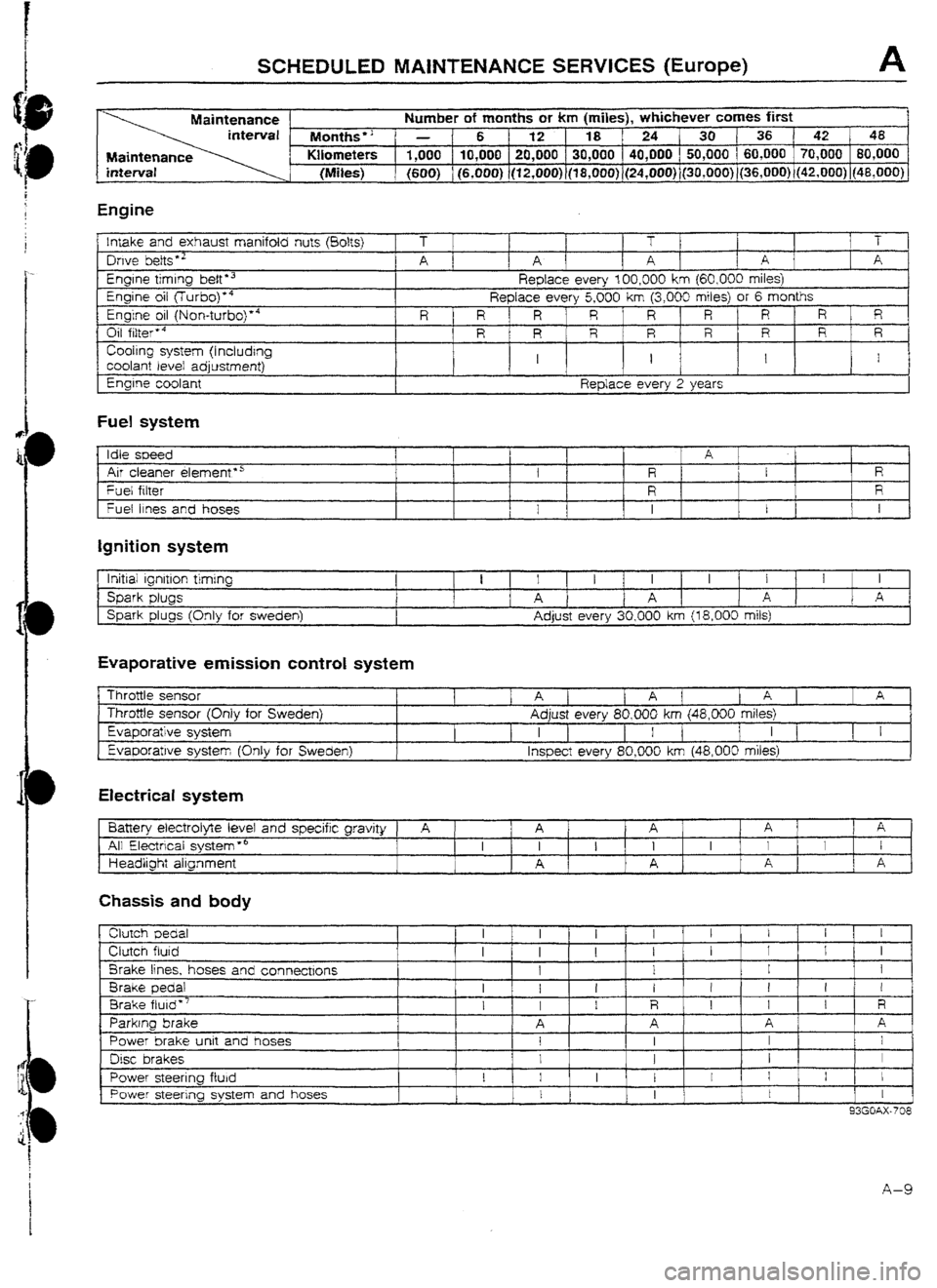
SCHEDULED MAtNTENANCE SERVICES (Europe) A
Maintenance Number of months or km (miles), whichever comes first
Months” - 6 1 12 18 ‘24 30136 42 48
Maintenance Kilometers 1,000 10,000 20,000 30,000 40,000 50,000 ( 60,000 70,000 80,000
(Miles) (600) (6,000) (12,OOO)~(l8,0~0) (24,000) (3O,UOO))(36,000) (42,000) j48,OOU)
Engine
!nrake and exhaust manifold nuts (80&j
Owe belts *’
Engrne timing belt l 3
Engine oil flurbo)‘4
Engine oil (Non-turbo)“4
Oil filter’4
Cooling system (I ncludrng
coolant level adjustment)
Engine coolant T 1 T T
A 1 1 A A 1 A A
Reptace every 100,000 km
{60,000 miles)
Replace every 5,000 km (3,000 miles) or 6 months
R R 1 R R R R ‘ R R R
R R R R R R R ’ R
I I I I
Replace every 2 years
Fuel system
Idle soeed
I A 1
Air cleaner elemenf*5 I f R E
R
Fuel fitter
R R
fuel 11~s and hoses 1
t 1 I I I I
Ignition system
lrritiai ignition timing
Spark plugs
Spark plugs (Only for Sweden) 1 I I I 1 I I 1 I I 1 I
A 1 A A 1 A
Adjust every 30,000 km {
18,000 mils)
Evaporative emission control system
Throttle sensor
Throttle sensor (Only for
Sweden)
Evaporative system Evaporatwe system Khlv
for Sweden) 1 1 Aj 1 A ( [ A ] 1 A
Adjust every 80,000 km (48,000 miles)
I 1 I [ I 1
I I [ 1 I
lnsoect everv 80.000 km (48.000 miles)
Electrical system
Battery electrolyte level and specific gravity
A 1 A A ’ 1 A ; A *
All Electrical system *’ I I 1 I I I I I I
Headlight alignment A A A I
c I A ,
Chassis and body
clutch Dedal
Clutch fluid
Brake lines, hoses and connectrons
Brake pedal
Brake fluid”’
Parking brake
Power brake unit and hoses
Disc brakes
Power steering fluid
Power steering system and hoses I
I I 1 1 1 I I
I I
I
I I I I 1 1 I
1
1 I I
I I I I t ! I I
I I I R I 1 I R
A A A A
I I I I
I 1 I 1
I 1 I I I I j I ,
I
I 1 I 1
I
93GOAX-708
A-9
Page 107 of 677
I
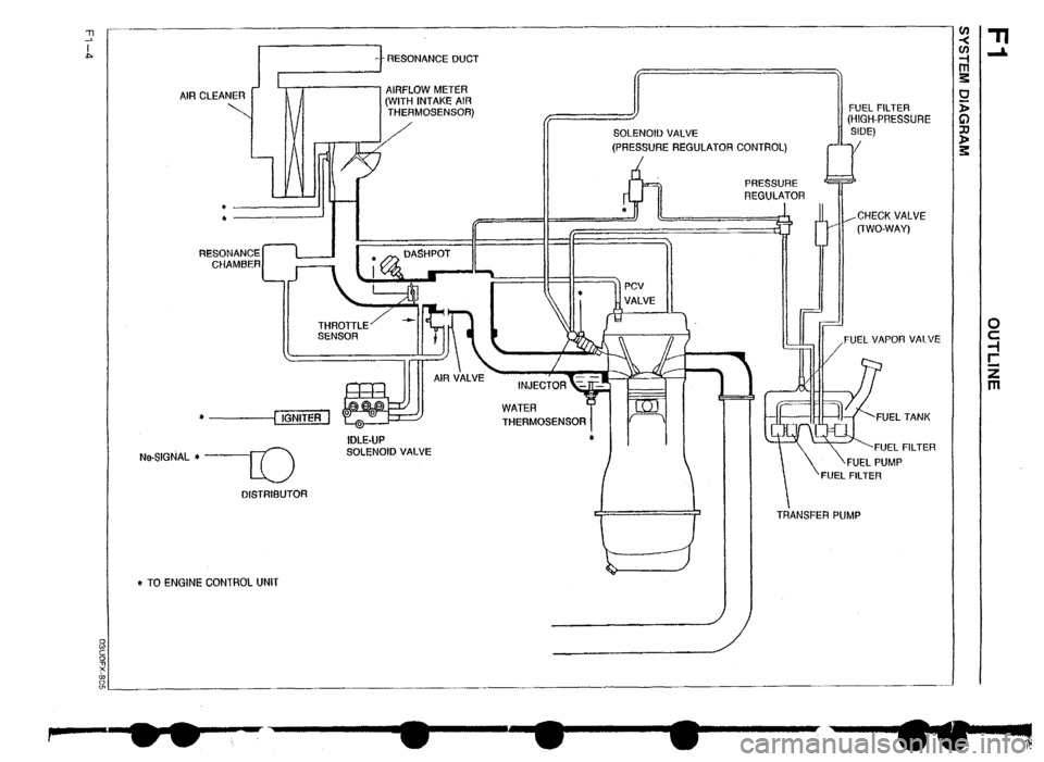
(WITH INTAKE AIR
THERMOSENSOR) AIR CLEANER METER
RESONANCE
CHAMBER /
SOLENOID VALVE
(PRESSURE REGULATOR CONTROL) FUEL FILTER
(HIGH-PRESSURE
SIDE)
P-“---j
Ne-S’GtiAL * ----El
DlSTRlfjUTOR IDLE-UP
SOLENOID VALVE
* TO ENGINE CONTROL UNIT ,CHECKVALVE
(TWO-WAY)
FUEL VAPOR VALVE
*
THERMOSENSOR
‘FUEL PUMP
FUEL FILTER
I TRANSFER PUMP
Page 112 of 677
SUPPLEMENTAL SERVICE INFORMATION, FUEL SYSTEM Fl
SUPPLEMENTAL SERVICE INFORMATION
The following points in this section are changed in comparison with Mazda 323 Workshop Manuals
(I 203-I U-89F, 1204-I O-89F, I2061 O-89F).
fuel tank
l Removal I Inspection I Installation
4x4 control unit (Fuel pump control unit)
l Inspection procedure added
l Replacement procedure added
Transfer pump switch
l Inspection procedure added
l Replacement procedure added
Transfer pump
l Inspection procedure added
l Replacement procedure added
Exhaust system components
l Removai I Inspection I installation 93GOF? -706
FUELSYSTEM
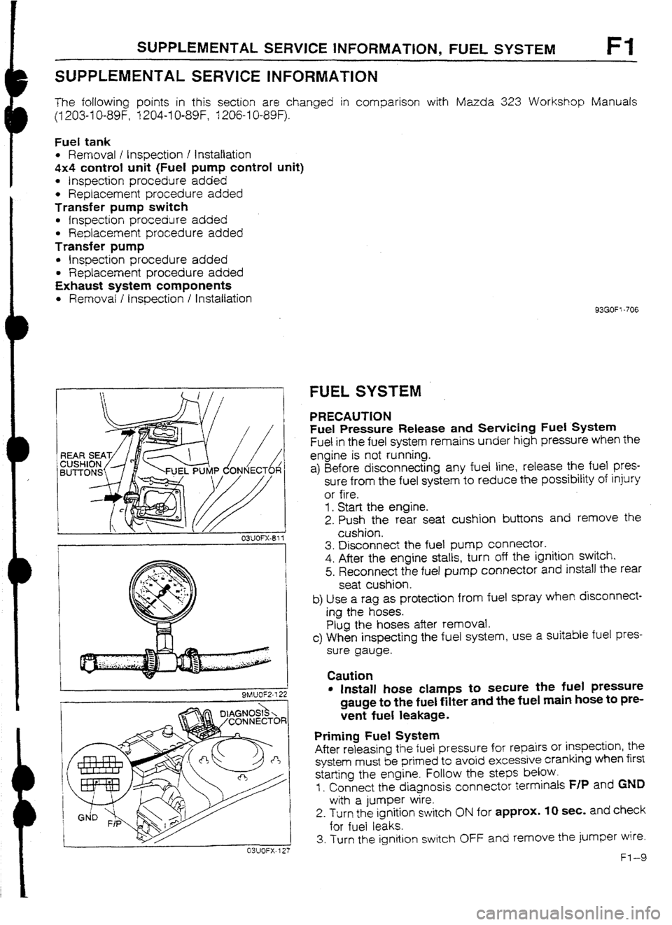
PRECAUTION
Fuel Pressure Release and Sewicing Fuel System
Fuel in the fuel system remains under high pressure when the
engine is not running.
a) Before disconnecting any fuel line, release the fuel
pres-
sure from the fuel system to reduce the possibility of injury
or fire.
1. Start the engine.
2. Push the rear seat cushion buttons and remove the
cushion.
3. Disconnect the fuel pump connector.
4. After the engine stalls, turn off the ignition switch.
5. Reconnect the fuel pump connector and install the rear
seat cushion.
b) Use a rag as protection from fuel spray when disconnect-
ing the hoses.
Plug the hoses after removal.
c> When inspecting the fuel system, use a suitable fuel pres-
sure gauge.
Caution
l Install hose clamps to secure tile fuel pressure
gauge to the fuel filter and the fuel main hose to pre-
vent fuel leakage.
Priming Fuel System
After releasing the fuel pressure for repairs or inspection, the
system must be primed to avoid excessive cranking when first
starting the engine. Follow the
steps below.
I. Connect the diagnosis connector terminals F/P and GND
with a jumper wire.
2. Turn the ignition switch ON for approx. IO sec. and check
for fuel leaks.
3. Turn the ignition switch OFF and remove the jumper wire.
Fl-9
Page 123 of 677

SOLENOID VALVE
CHECK VALVE
r----+ (PURGE CONTROL)
CHiRCOAL
I CANISTER
INTERCOOLER 11 ’ 1 ‘I A-4
II II -
AIR , BYPASS
II ,.-ok----,/ ,CHECK VALVE
(TWO-WAY)
1-1
---II
-d KNO&
II II I I II VALVE
VALVE
THERMOSENSOR
c
I 31c
SENSOR 1 k---k FUEL FILTER
TRANSFER
PUMP
WASTEGATE 7
II t I III TURtiOCHARGERI~
I SOLENOID I II - i 1 WASTFGATF II I
AlOCI fuAl RAlz-rCD
VALVE
le-SIGNAL* -
EJ 0
G-SIGNAL-
DISTRIBUTOR
CATALYTIC CONVERTER ftl”FLLt”” IVIL I =r,
(WITH INTAKE THERMOSENSOR)
*TO ENGINE CONTROL UNIT
Page 167 of 677
F2 FUEL SYSTEM
FUEL
SYSTEM
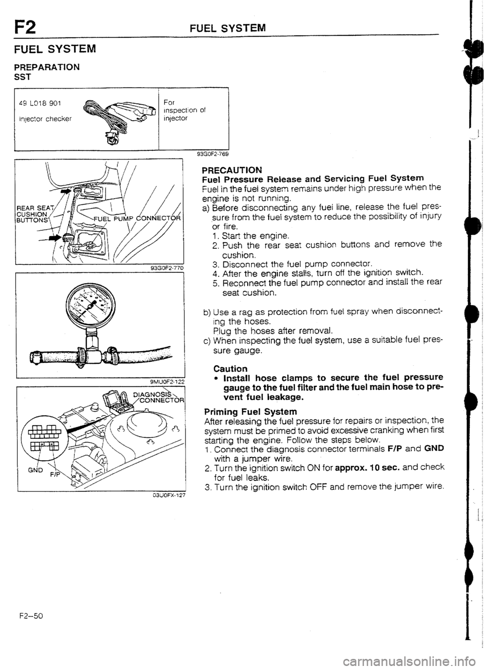
PREPARATlON
SST
49 LO18 901
Injector checker For
lnsgectlon of
injector
93GOF2.770
9MUOF2-722
03UOFX-7 27
F2-50
PRECAUTION
Fuel Pressure
Release and Servicing Fuel System
Fuel in the fuel system remains under high pressure when the
engine is not running.
a) Before disconnecting any fuel line, release the fuel pres-
sure from the fuel system to reduce the possibility of injury
‘or fife,
1. Start the engine.
2. Push the rear seat cushion buttons and remove the
cushion,
3. Disconnect the fuel pump connector.
4. After the engine stalts, turn off the ignition switch.
5. Recpnnect the fuel pump connector and install the rear
seat cushion.
b) Use a rag as protection from fuel spray when disconnect-
ing the hoses.
Plug the hoses after
removal.
c) When inspecting the fuel system, use a suitable fuel pres-
sure gauge.
Caution
l Install hose clamps to secure the fuel pressure
gauge to the fuel filter and the fuel main hose to pre-
vent fuet leakage.
Priming Fuel System
After releasing the fuel pressure for repairs or inspection, the
system must be primed to avoid excessive cranking when first
starting the engine. Follow the steps
below.
1. Connect the diagnosis connector terminals F/P and GND
with a jumper wire.
2. Turn the ignition switch
ON for approx. 10 set, and check
for fuel leaks.
3. Turn the ignition switch OFF and remove the jumper wire.