charging MAZDA 232 1990 Workshop Manual Suplement
[x] Cancel search | Manufacturer: MAZDA, Model Year: 1990, Model line: 232, Model: MAZDA 232 1990Pages: 677, PDF Size: 61.19 MB
Page 106 of 677

OUTLINE Fl
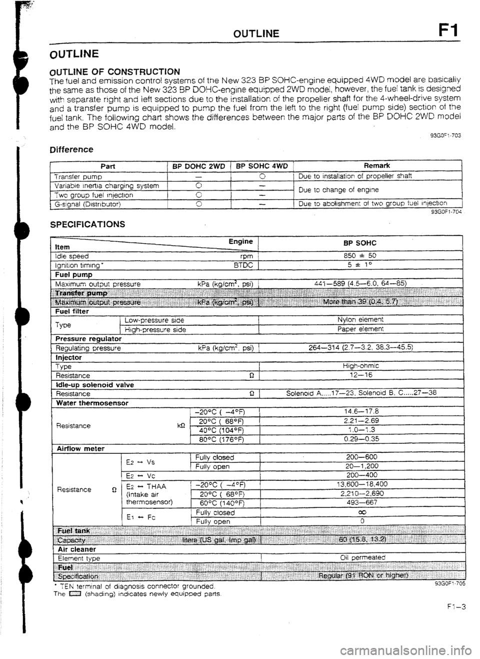
OlJTLlNE OF CONSTRUCTION
The fuel and emission control systems of the New 3.23 BP SOHC-engine equipped 4WD model are basically
the same as those of the New 323 8P DOHC-engine equipped 2WD model, however, the fuel tank is designed
with separate right
and left sections due to the installation of the propeller shaft for the 4-wheel-drive system
and
a transfer pump is equipped to pump the fuel from the left to the right (fuei pump side) section of the
fue! tank. The following chart shows the differences between the major parts of the BP DO% 2WD model
and the BP SOHC 4WD model.
33GO”l-703
Difference
I t
Part BP DOHC 2WD 1 BP SOHC 4WD Remark Transfer pump -
0 Due to
installation of propeller shaft
Variable Inertra charging system 0 -
Two group fuel qectron Due to change of engine
-
G-slgnal (Drstnbutor) 0
I -
Due to abolishment of two group fuel Injection
93GOfl-70s
SPECIFICATIONS
Item
Idle speed
Ignition timing * Engine
vm
BTDC BP SOHC
850 * 50
5 * to
Fuel DUtTlD I
Fuel filter
Type Low-pressure side
Htgh-pressure side Nylon element
Paper element
Pressure regulator
Regulating pressure kPa (kglcm2, psi) 1 264-314 (2.7-3.2, 38.3-45.5)
In
jfXt0r
Type
Resistance High-ohmic
12-16
Idbup solenoid vatve
Resistance Solenoid A _.._. 17-23, Solenoid 5, C ._... 27-36
Water themosensor
R&stance -20% ( -4OF)
kQ - . 20°C ( 689=)
40% (104OFj
80°C (176OF) 14.6-l 7.8
2.2-I -2.69
1.0-l -3
0.29-0.35
l TEN terminal of dragnosrs connector grounded.
The a (shading) rndrcates newly equipped parts
Page 131 of 677
![MAZDA 232 1990 Workshop Manual Suplement F2 TURBOCHARGER CONTROL [BP TURBO]
93GOF.Z721
!=2-14 LARGE
+ FULLY OPEN
BYPASS AIR
i 8EGlNNIp
AMOLIN OF OPEN
SMALIL
430 VACUUM
(5-l) mmt-lg
TURBOCHARGER OnW
INLET
lntercooler
The air-to-a MAZDA 232 1990 Workshop Manual Suplement F2 TURBOCHARGER CONTROL [BP TURBO]
93GOF.Z721
!=2-14 LARGE
+ FULLY OPEN
BYPASS AIR
i 8EGlNNIp
AMOLIN OF OPEN
SMALIL
430 VACUUM
(5-l) mmt-lg
TURBOCHARGER OnW
INLET
lntercooler
The air-to-a](/img/28/57056/w960_57056-130.png)
F2 TURBOCHARGER CONTROL [BP TURBO]
93GOF.Z721
!=2-14 LARGE
+ FULLY OPEN
BYPASS AIR
i 8EGlNNIp
AMOLIN OF OPEN
SMALIL
430 VACUUM
(5-l) mmt-lg
TURBOCHARGER OnW
INLET
lntercooler
The air-to-air intercooler utilizes fresh air flow through the in-
tercooler core to reduce the intake air temperature.
If
the air compressed by the turbocharger was sent directly
into the combustion chamber without passing through the in-
tercooler, the charging air efficiency would be
reduced by the
high temperature of the intake aii-.
The intercooler, by cooling this high temperature air, substan-
tially increases the charging air efficiency
and engine output,
as well as supressing ignition knocking by reducing the com-
bustion gas temperature.
The intercooler is mounted at
the left front of the vehicle.
Air Bypass Valve
The air bypass valve bypasses intake air from the air funnel
to before the turbocharger in order to reduce air vibration noise
during deceleration.
When the throttle valve is closed suddenly during high-rpm
and heavy-load operation, air vibration occurs between the
throttle vatve and the turbocharger as a result of pressuriza-
tion
caused by inertia of the intake air. This system prevents
such noise.
Page 192 of 677

CHARGWIG SYSTEM G
CHARGING SYSTEM
PREPARATION
SST
49 0118 85OC For
Puller, ball joint removal of ball
joint
93GOGX-707
ALTERNATOR (RHD)
Removal / Installation
I. Remove in the order shown in the figure.
2. Install in the reverse order of removal, referring to Installation Note.
1
37-52 (3.8-5.3, 27 37-52 (3.8-5.3, 27
72.0, 65-81)
37-52 (3.8-5.3, 27-38) 37-52 (3.8-5.3, 27-38)
N-m (m-kg, ft-lb) N-m (m-kg, ft-lb)
93G?GX-70 93G?GX-70
I. Negative battery cable I. Negative battery cable 7. Stabilizer (Right) 7. Stabilizer (Right)
2. Tire and wheel (Right front) 2. Tire and wheel (Right front) Installation Installation Note . . . . . . . . . . . . . -. . I -. . . . - . . . . page G-6 Note . . . . . . . . . . . . . -. . I -. . . . - . . . . page G-6
3. Undercover 3. Undercover 8. Lower arm (Right) 8. Lower arm (Right)
4. Crossmember 4. Crossmember 9. Driveshaft (Right) 9. Driveshaft (Right)
5. Front exhaust pipe 5. Front exhaust pipe IO. Alternator connectors IO. Alternator connectors
6. Tie-rod end 6. Tie-rod end 11. Alternator 11. Alternator
Removal Note ._....._.........._..._ ._..... page G-6 Removal Note ._....._.........._..._ ._..... page G-6 Remove from below Remove from below
G-5 G-5