ENGINE CONTROL SYSTEM MAZDA 323 1989 Factory Repair Manual
[x] Cancel search | Manufacturer: MAZDA, Model Year: 1989, Model line: 323, Model: MAZDA 323 1989Pages: 1164, PDF Size: 81.9 MB
Page 1 of 1164
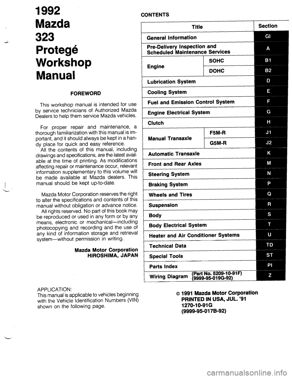
1992
Mazda
CONTENTS
Protege
Workshop
Manual
FOREWORD
This workshop manual is intended for use
by service technicians of Authorized Mazda
Dealers to help them service Mazda vehicles.
For proper repair and maintenance, a
thorough familiarization with this manual is im-
portant, and it should always be kept in a han-
dy place for quick and easy reference.
All the contents of this manual, including
drawings and specifications, are the latest avail-
able at the time of printing. As modifications
affecting repair or maintenance occur, relevant
information supplementary to this volume will
be made available at Mazda dealers. This
manual should be kept up-to-date.
Mazda Motor Corporation reserves the right
to alter the specifications and contents of this
manual without obligation or advance notice.
All rights reserved. No part of this book may
be reproduced or used in any form or by any
means, electronic or mechanical-including
photocopying and recording and the use of
any kind of information storage and retrieval
system-without permission in writing.
Mazda Motor Corporation
HIROSHIMA, JAPAN
APPLICATION:
This manual is applicable to vehicles beginning
with the Vehicle Identification Numbers (VIN)
shown on the following page.
Title
General Information Section
Pre-Delivery Inspection and
Scheduled Maintenance Services
SOHC
Engine
DOHC
Lubrication System
Cooling System
Fuel and Emission Control System
Engine Electrical System
Clutch
FSM-R
Manual Transaxle
GSM-R
Automatic Transaxle
Front and Rear Axles
Steering System
Braking System
Wheels and Tires
Suspension
Body
--
Body Electrical System
Heater and Air Conditioner Systems
Technical Data
Special Tools
Parts Index
Wiring DNvam
I Part No. 5209-10-91 F)
9999~95-019(3-92)
o 1991 Mazda Motor Corporation
PRINTED IN USA, JUL. ‘91
1270-l O-91 G
(9999-95-0178-92)
Page 12 of 1164
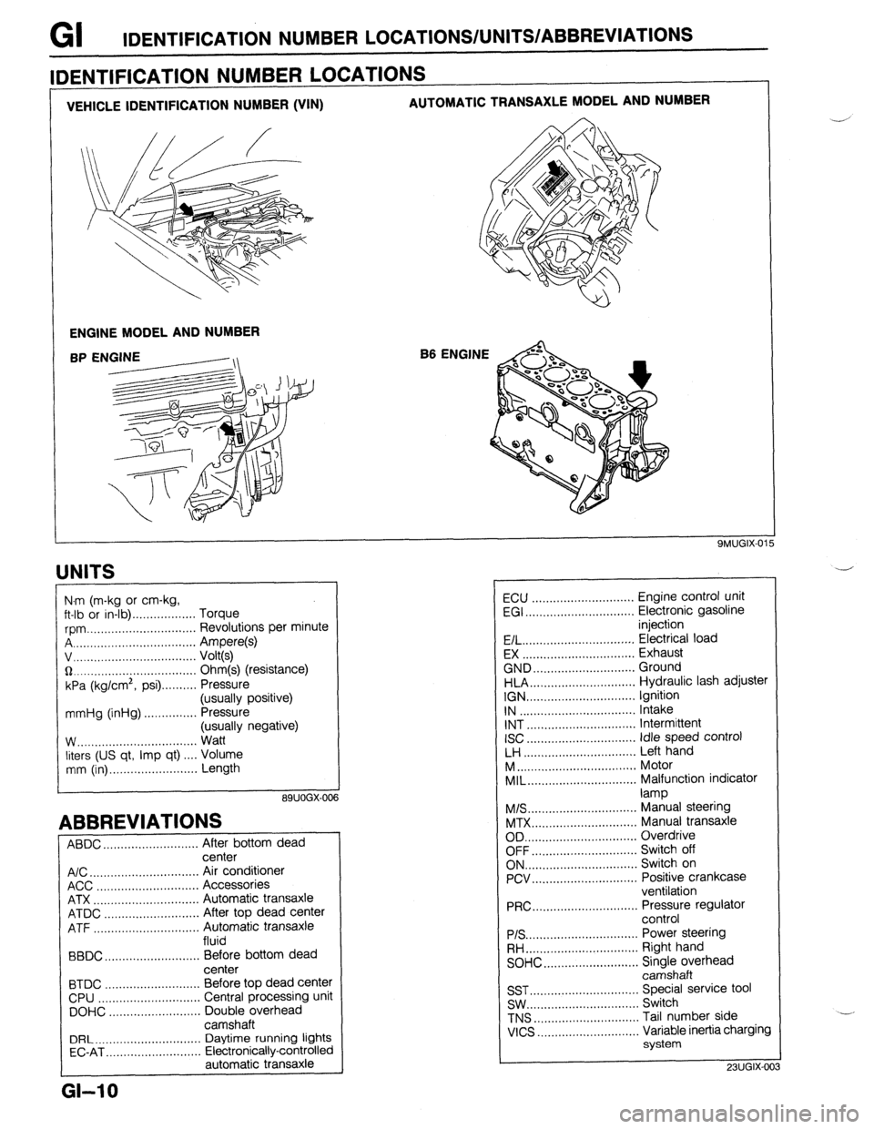
GI IDENTIFICATION NUMBER LOCATIONS/UNITS/ABBREVlATlONS
VEHICLE IDENTIFICATION NUMBER (VIN) AUTOMATIC TRANSAXLE MODEL AND NUMBER
ENGINE MODEL AND NUMBER
B6 ENGINE
IDENTIFICATION NUMBER LOCATIONS
UNITS
I
N.m (m-kg or cm-kg,
ft-lb or in-lb) . . . . . . . . . . . . . . . . . . Torque
rpm ._..,,,.............,.......... Revolutions per minute
A . . . . . . . . . . . . . . . . . Ampere(s)
v, . . . . . . . . . . . . . .
Volt(s)
$2 _....._..,......................... Ohm(s) (resistance)
kPa (kg/cm2,
psi) . . . . . . . . . . Pressure
(usually positive)
mmHg (inHg) . . . . . . . . . . . . . . . Pressure
(usually negative)
W.. . . . . . . . . . . .
Watt
liters (US qt, Imp qt) ,... Volume
mm (in) ..,......,...,........... Length
89UOGX-00
ABBREVIATIONS
ABDC . . . . . . . . . . . . . . . . . . . . .
After bottom dead
center
A/C . . . . . . . . . . . . . . . . . . . . . . . . . . . . . . .
Air conditioner
ACC ..,.,...... 3 . . . . . . . . . . . . . . . . . Accessories
ATX . . . . . . . . . . . . . . . . . . . . . . . . . . . . . . Automatic transaxle
ATDC ..,,...,...,............... After top dead center
ATF . . . . . . . . . . . . . . . . . Automatic transaxle
fluid
BBDC ,,..,.......,...,......,... Before bottom dead
center
BTDC .,......,...............,.. Before top dead center
CPU ..,,.......,...,..........,.. Central processing unit
DOHC ..,...,..,............,,.. Double overhead
camshaft
DRL ____.......................... Daytime running lights
EC-AT .,_.......,............,,.. Electronically-controlled
automatic transaxle
L
GI-10
ECU ............................. Engine control unit
EGI ............................... Electronic gasoline
injection
E/L.. .............................. Electrical load
EX ................................ Exhaust
GND.. ........................... Ground
HLA.. ............................ Hydraulic lash adjuster
IGN ............................... Ignition
IN ................................. Intake
INT ............................... Intermittent
ISC
............................... idle speed control
LH ................................ Left hand
M..
................................ Motor
MIL..
............................. Malfunction indicator
lamp
M/S..
............................. Manual steering
MTX.. ............................ Manual transaxle
OD ................................ Overdrive
OFF.. ............................ Switch off
ON.. .............................. Switch on
PCV.. ............................ Positive crankcase
ventilation
PRC..
............................ Pressure regulator
control
PIS ................................ Power steering
RH..
.............................. Right hand
SOHC.. .........................
z;;kiprhead
SST ............................... Special service tool
SW.. .............................. Switch
TNS
.............................. Tail number side
VICS
............................. Variable inertia charging
system
23UGIX-00
Page 13 of 1164
CAUTION GI
CAUTION
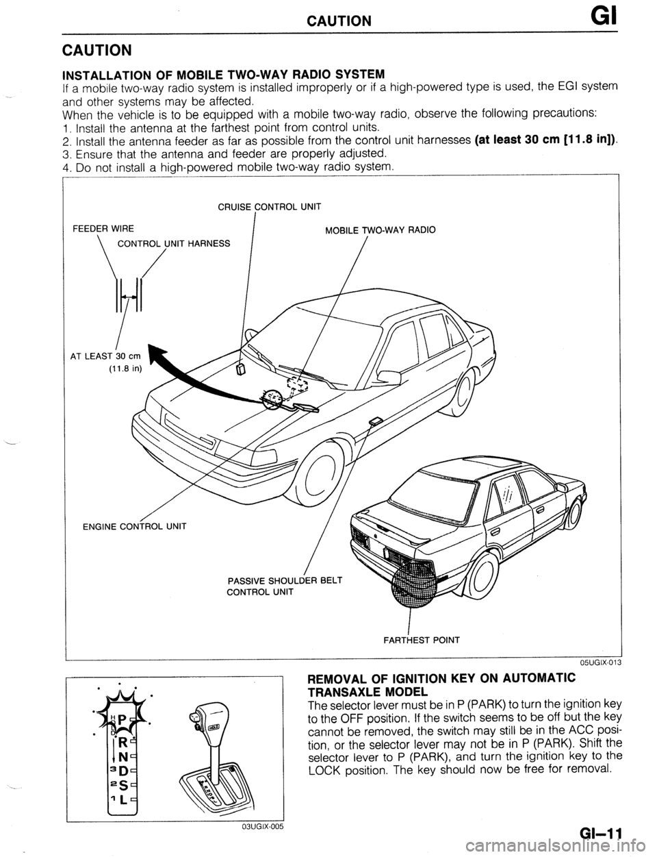
INSTALLATION OF MOBILE TWO-WAY RADIO SYSTEM
If a mobile two-way radio system is installed improperly or if a high-powered type is used, the EGI system
and other systems may be affected.
When the vehicle is to be equipped with a mobile two-way radio, observe the following precautions:
1. Install the antenna at the farthest point from control units.
2. Install the antenna feeder as far as possible from the control unit harnesses (at least 30 cm [11.8 in]).
3. Ensure that the antenna and feeder are properly adjusted.
4. Do not install a high-powered mobile two-way radio system.
CRUISE CONTROL UNIT
FEEDER WIRE
I MOBILE TWO-WAY RADIO
CONTROL UNIT HARNESS
/ /
4T LEAST b0
cm
(11.8 in)
OWGIX-013 ENGINE CONiROL UNIT
/
FARTiEST POINT
REMOVAL OF IGNITION KEY ON AUTOMATIC
TRANSAXLE MODEL
The selector lever must be in P (PARK) to turn the ignition key
to the OFF position. If the switch seems to be off but the key
cannot be removed, the switch may still be in the ACC posi-
tion, or the selector lever may not be in P (PARK). Shift the
selector lever to P (PARK), and turn the ignition key to the
LOCK position. The key should now be free for removal.
GI-1 1
Page 20 of 1164
PRE-DELIVERY INSPECTION
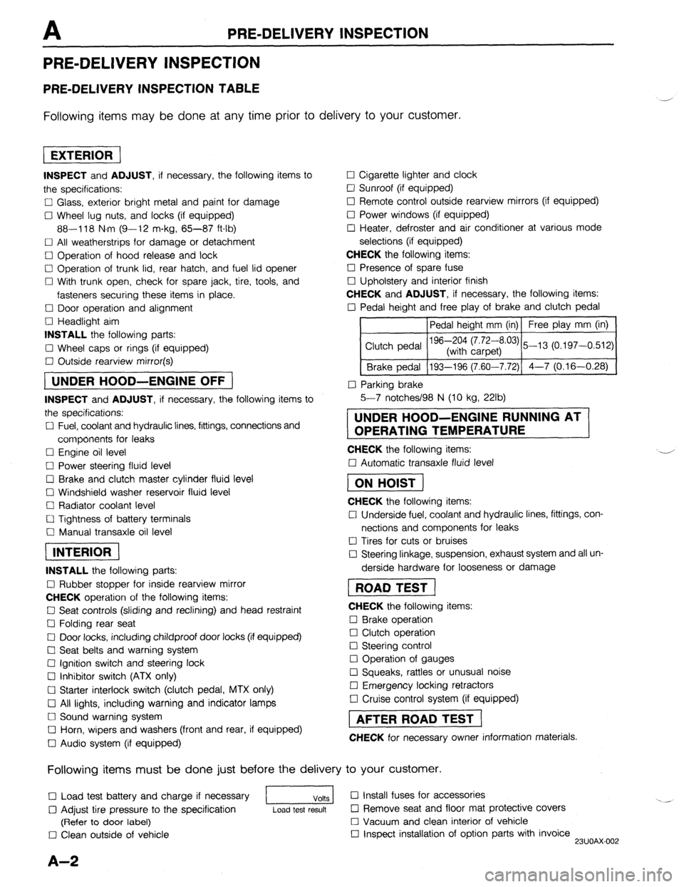
PRE-DELIVERY INSPECTION
PRE-DELIVERY INSPECTION TABLE
Following items may be done at any time prior to delivery to your customer.
INSPECT and ADJUST, if necessary, the following items to
the specifications:
0 Glass, exterior bright metal and paint for damage
Cl Wheel lug nuts, and locks (if equipped)
88-118 N.m (9-12 m-kg, 65-87 ft-lb)
q All weatherstrips for damage or detachment
0 Operation of hood release and lock
0 Operation of trunk lid, rear hatch, and fuel lid opener
Cl With trunk open, check for spare jack, tire, tools, and
fasteners securing these items in place.
Cl Door operation and alignment
Cl Headlight aim
INSTALL the following parts:
Cl Wheel caps or rings (if equipped)
q Outside rearview mirror(s)
1 UNDER HOOD-ENGINE OFF )
INSPECT and ADJUST, if necessary, the following items to
the specifications:
0 Fuel, coolant and hydraulic lines, fittings, connections and
components for leaks
Cl Engine oil level
0 Power steering fluid level
0 Brake and clutch master cylinder fluid level
El Windshield washer reservoir fluid level
Cl Radiator coolant level
Cl Tightness of battery terminals
Cl Manual transaxle oil level
riizmiq
INSTALL the following parts:
Cl Rubber stopper for inside rearview mirror
CHECK operation of the following items:
0 Seat controls (sliding and reclining) and head restraint
Cl Folding rear seat
0 Door locks, including childproof door locks (if equipped)
Seat belts and warning system
Cl Ignition switch and steering lock
0 Inhibitor switch (ATX only)
U Starter interlock switch (clutch pedal, MTX only)
Cl All lights, including warning and indicator lamps
Cl Sound warning system
Cl Horn, wipers and washers (front and rear, if equipped)
0 Audio system (if equipped) 0 Cigarette lighter and clock
0 Sunroof (if equipped)
II Remote control outside rearview mirrors (if equipped)
Cl Power windows (if equipped)
q Heater, defroster and air conditioner at various mode
selections (if equipped)
CHECK the following items:
Cl Presence of spare fuse
0 Upholstery and interior finish
CHECK and ADJUST, if necessary, the following items:
0 Pedal height and free play of brake and clutch pedal
Pedal height mm (in) Free play mm (in)
0 Parking brake
5-7 notches/98 N (10 kg, 22lb)
UNDER HOOD-ENGINE RUNNING AT
OPERATING TEMPERATURE
CHECK the following items:
q Automatic transaxle fluid level
[I
CHECK the following items:
Cl Underside fuel, coolant and hydraulic lines, fittings, con-
nections and components for leaks
0 Tires for cuts or bruises
0 Steering linkage, suspension, exhaust system and all un-
derside hardware for looseness or damage
[I
CHECK the following items:
0 Brake operation
0 Clutch operation
Cl Steering control
Cl Operation of gauges
q Squeaks, rattles or unusual noise
Cl Emergency locking retractors
0 Cruise control system (if equipped)
1 AFTER ROAD TEST (
CHECK for necessary owner information materials.
Following items must be done just before the delivery to your customer.
q Load test battery and charge if necessary
1 Volts 1 0 Install fuses for accessories
i.. _
0 Adjust tire pressure to the specification
Load test result cl Remove seat and floor mat protective covers
(Refer to door label) 0 Vacuum and clean interior of vehicle
0 Clean outside of vehicle q Inspect installation of option parts with invoice
23UOAX-002
A-2
Page 49 of 1164
.
ON-VEHICLE MAINTENANCE
Installation note
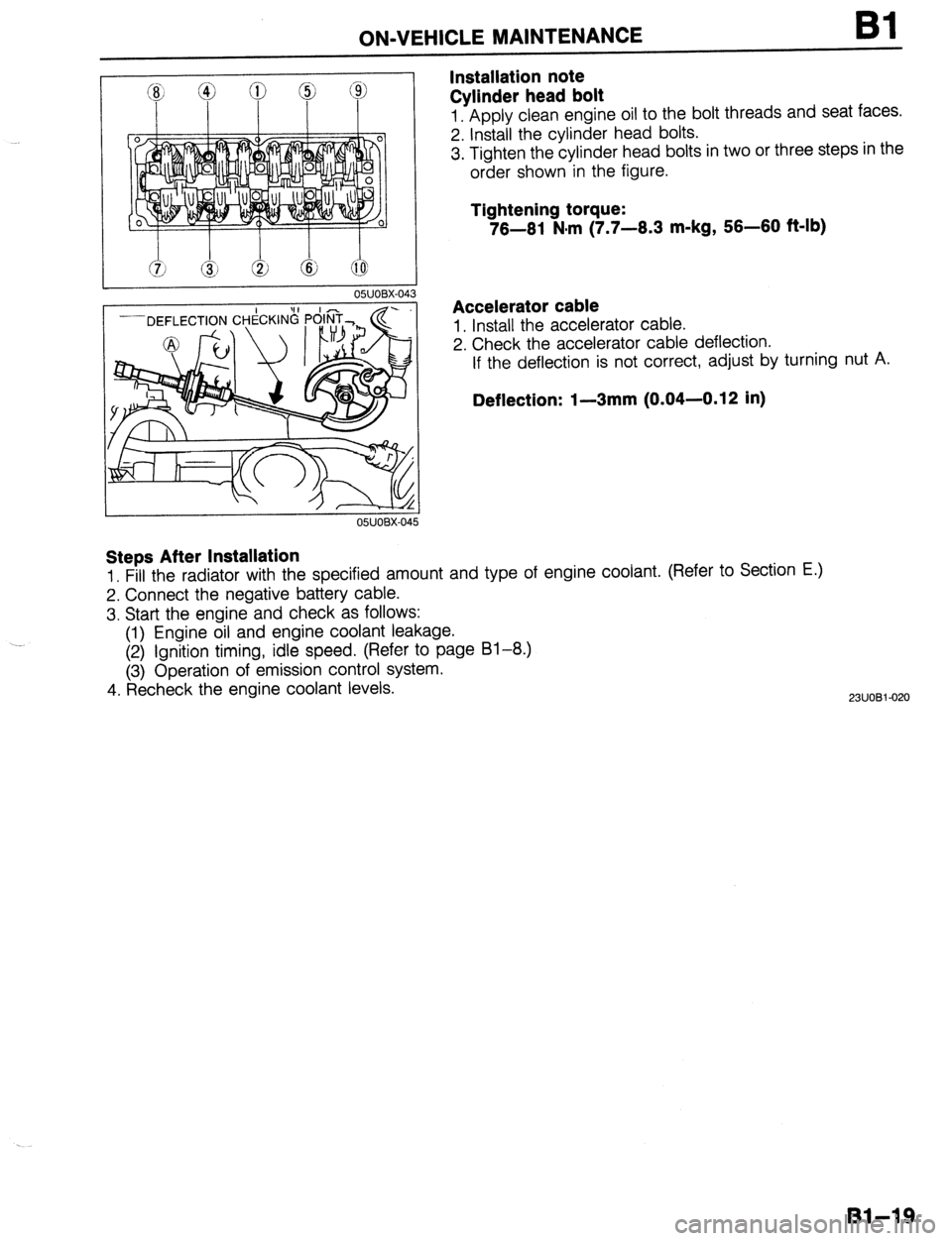
Cylinder head bolt Bl
1. Apply clean engine oil to the bolt threads and seat faces.
2. Install the cylinder head bolts.
3. Tighten the cylinder head bolts in two or three steps in the
order shown in the figure.
Tightening torque:
76-61 N#m (7.7-6.3 m-kg, 56-60 f&lb)
Accelerator cable
1. Install the accelerator cable.
2. Check the accelerator cable deflection.
If the deflection is not correct, adjust by turning nut A.
Deflection: I-3mm (0.04-0.12 in)
Steps After Installation
1. Fill the radiator with the specified amount and type of engine coolant. (Refer to Section E.)
2. Connect the negative battery cable.
3. Start the engine and check as follows:
(1) Engine oil and engine coolant leakage.
(2) Ignition timing, idle speed. (Refer to page 81-8.)
(3) Operation of emission control system.
4. Recheck the engine coolant levels.
2311081-020
Bl-19
Page 132 of 1164
INSTALLATION
OWOBX-27!
Resonance chamber
1. Install the resonance chamber.
Tightening torque:
7.8-l 1 N-m (80-I 10 cm-kg, 69-95 in-lb)
Undercover and side cover
1. Install the undercover and side cover.
Steps After Installation
1. If the engine oil was drained, fill with the specified amount and type of engine oil.
(Refer to Section D.)
Accelerator cable
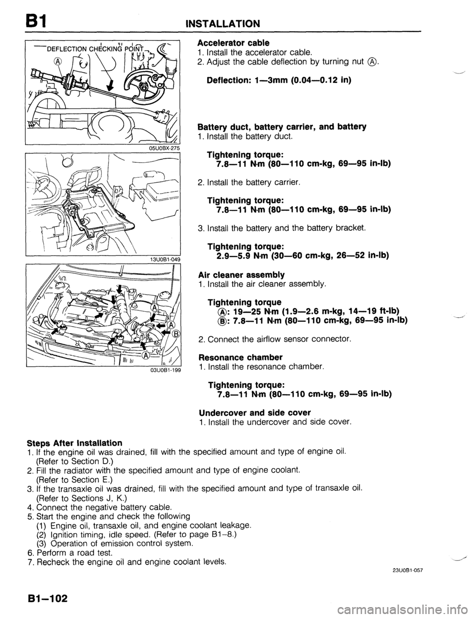
1. Install the accelerator cable.
2. Adjust the cable deflection by turning nut @.
Deflection: I-3mm (0.04-0.12 in)
Battery duct, battery carrier, and battery
1. Install the battery duct.
Tightening torque:
7.8-l 1 N-m (80-l 10 cm-kg, 69-95 in-lb)
2. Install the battery carrier.
Tightening torque:
7.8-11 N.m (80-110 cm-kg, 69-95 in-lb)
3. Install the battery and the battery bracket.
Tightening torque:
2.9-5.9 N*m (30-60 cm-kg, 26-52 in-lb)
Air cleaner assembly
1. Install the air cleaner assembly.
lightening torque
@: 19-25 N-m (1.9-2.6 m-kg, 14-19 ft-lb)
@: 7.8-l 1 N-m (80-I 10 cm-kg, 69-95 in-lb)
2. Connect the airflow sensor connector.
2. Fill the radiator with the specified amount and type of engine coolant.
(Refer to Section E.)
3. If the transaxle oil was drained, fill with the specified amount and type of transaxle oil.
(Refer to Sections J, K.)
4. Connect the negative battery cable.
5. Start the engine and check the following
(1) Engine oil, transaxle oil, and engine coolant leakage.
(2) Ignition timing, idle speed. (Refer to page 61-8.)
(3) Operation of emission control system.
6. Perform a road test,
7. Recheck the engine oil and engine coolant levels.
.-’
23UOBl-057
81-102
Page 153 of 1164
ON-VEHICLE MAINTENANCE
DEFLECTION CHECKING POINT
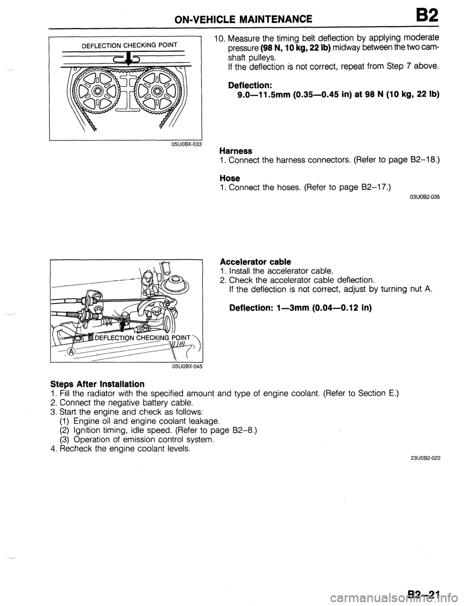
05UOBX-03 3 10. Measure the timing belt deflection by applying moderate
pressure (98 N, 10 kg, 22 lb) midway between the two cam-
shaft pulleys.
If the deflection is not correct, repeat from Step 7 above.
Deflection:
9.0-11.5mm (0.35-0.45 in) at 98 N (10 kg, 22 lb)
Harness
1. Connect the harness connectors. (Refer to page 82-l 8.)
Hose
1. Connect the hoses. (Refer to page 82-17.)
03UOB2-035
Accelerator cable
1. Install the accelerator cable.
2. Check the accelerator cable deflection.
If the deflection is not correct, adjust by turning nut A.
Deflection: l-3mm (0.04-0.12 In)
Steps After Installation
1. Fill the radiator with the specified amount and type of engine coolant. (Refer to Section E.)
2. Connect the negative battery cable.
3. Start the engine and check as follows:
(1) Engine oil and engine coolant leakage.
(2) Ignition timing, idle speed. (Refer to page B2-8.)
(3) Operation of emission control system.
4. Recheck the engine coolant levels.
2311082-022
B2-21
Page 234 of 1164
92 INSTALLATION
RESOiANCE CHAMBER
03UOBZ-154
Accelerator cable
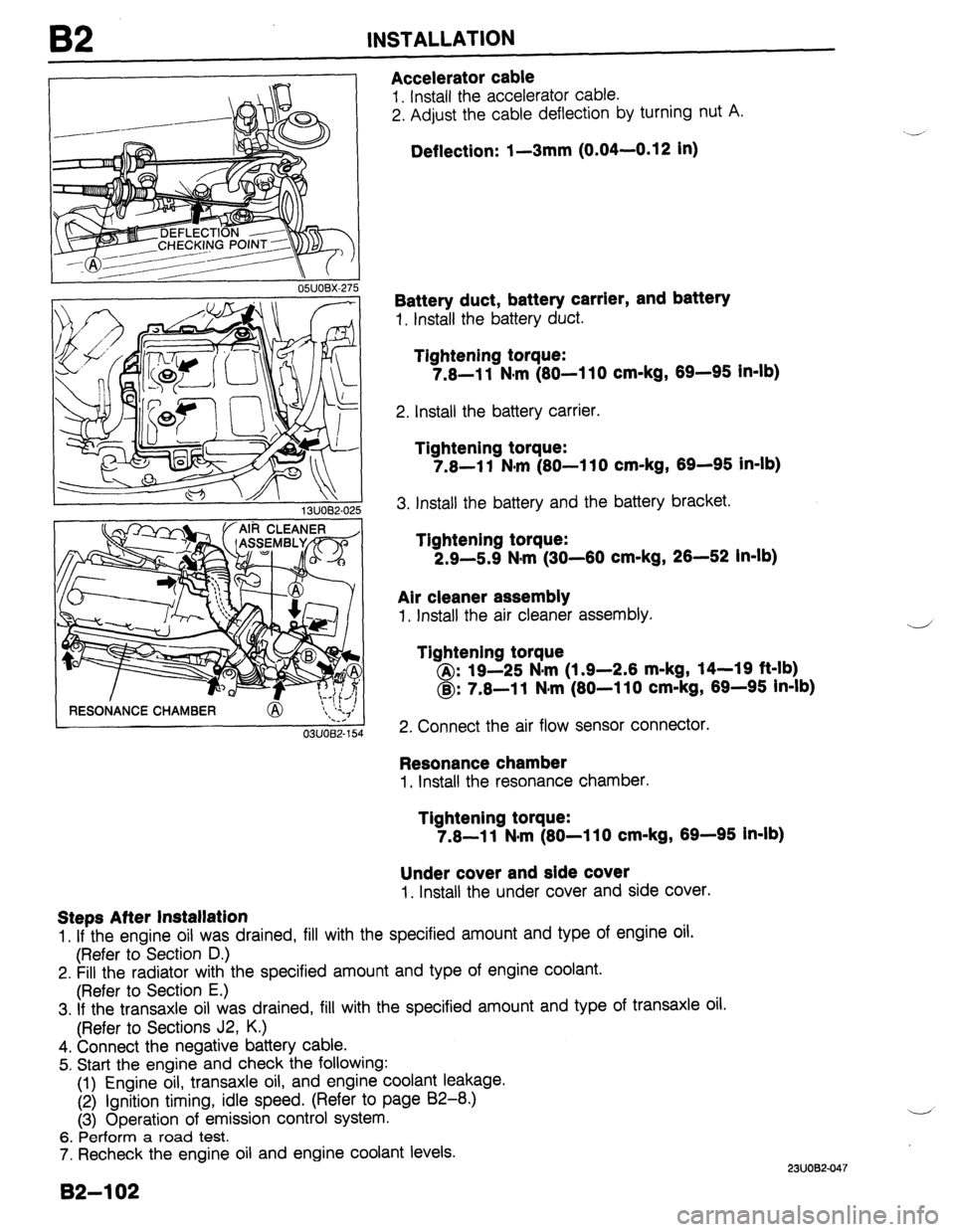
1. Install the accelerator cable.
2. Adjust the cable deflection by turning nut A.
Deflection: 1-3mm (0.04-0.12 in)
Battery duct, battery carrier, and battery
1. Install the battery duct.
Tightening torque:
7.8-l 1 Nlm (80-l 10 cm-kg, 69-96 In-lb)
2. Install the battery carrier.
Tightening torque:
7.8-l 1 N*m (80-l 10 cm-kg, 69-96 in-lb)
3. Install the battery and the battery bracket.
Tightening torque:
2.9-5.9 N*m (30-60 cm-kg, 26-52 in-lb)
Air cleaner assembly
1. Install the air cleaner assembly.
Tightening torque
@: 19-25 N#m (1.9-2.6 m-kg, 14-19 ft-lb)
@: 7.8-l 1 N*m (80-l 10 cm-kg, 69-95 In-lb)
2. Connect the air flow sensor connector.
Resonance chamber
I, Install the resonance chamber.
Tightening torque:
7.8-l 1 N#m (80-l 10 cm-kg, 69-95 In-lb)
Under cover and side cover
1. Install the under cover and side cover.
Steps After Installation
1. If the engine oil was drained, fill with the specified amount and type of engine oil.
(Refer to Section D.)
2. Fill the radiator with the specified amount and type of engine coolant.
(Refer to Section E.)
3. If the transaxle oil was drained, fill with the specified amount and type of transaxle oil.
(Refer to Sections J2, K.)
4. Connect the negative battery cable.
5. Start the engine and check the following:
(1) Engine oil, transaxle oil, and engine coolant leakage.
(2) ignition timing, idle speed. (Refer to page 82-8.)
(3) Operation of emission control system.
6. Perform a road test.
7. Recheck the engine oil and engine coolant levels.
B2-102
2311082.047
Page 267 of 1164
F
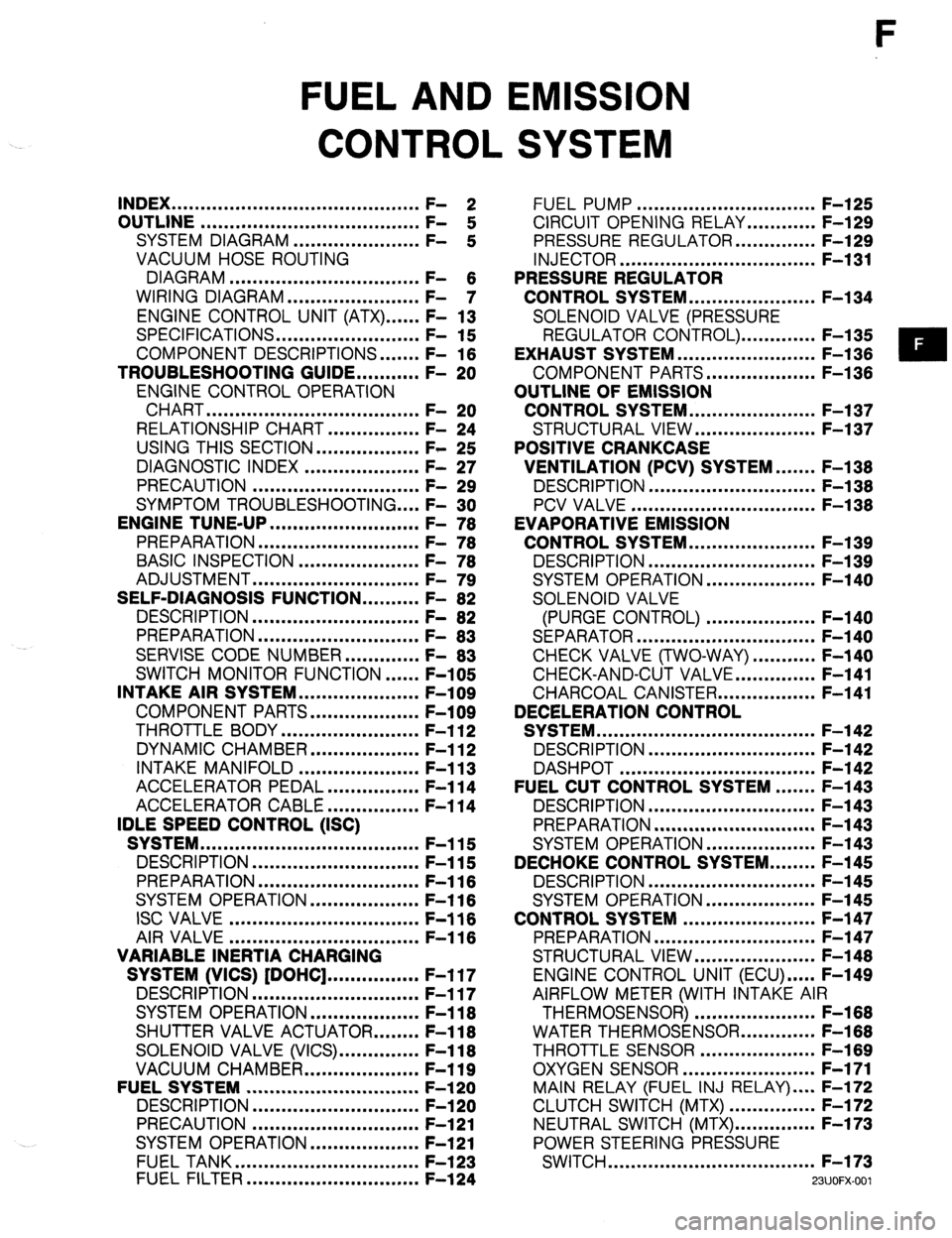
FUEL AND EMISSION
CONTROL SYSTEM
INDEX ...........................................
OUTLINE ...................................... ;: 2
SYSTEM DIAGRAM ...................... F-
:
VACUUM HOSE ROUTING
DIAGRAM .................................
WIRING DIAGRAM ....................... F- 6
- 7
ENGINE CONTROL UNIT (ATX) ...... F- 13
SPECIFICATIONS.. ....................... F- 15
COMPONENT DESCRIPTIONS.
...... F- 16
TROUBLESHOOTING GUIDE.. ......... F- 20
ENGINE CONTROL OPERATION
CHART
..................................... F- 20
RELATIONSHIP CHART.. .............. F- 24
USING THIS SECTION .................. F- 25
DIAGNOSTIC INDEX .................... F- 27
PRECAUTION ............................. F- 29
SYMPTOM TROUBLESHOOTING .... F- 30
ENGINE TUNE-UP
.......................... F- 76
PREPARATION ............................
F- 76
BASIC INSPECTION ..................... F- 78
ADJUSTMENT .............................
F- 79
SELF-DIAGNOSIS FUNCTION .......... F- 82
DESCRIPTION .............................
F- 82
PREPARATION
............................
F- 83
SERVISE CODE NUMBER.. ........... F- 83
SWITCH MONITOR FUNCTION ...... F-105
INTAKE AIR SYSTEM.. ................... F-109
COMPONENT PARTS.. ................. F-109
THROTTLE BODY ........................ F-l 12
DYNAMIC CHAMBER ................... F-l 12
INTAKE MANIFOLD ..................... F-l 13
ACCELERATOR PEDAL ................ F-l 14
ACCELERATOR CABLE ................ F-l 14
IDLE SPEED CONTROL (ISC)
SYSTEM ......................................
F-115
DESCRIPTION ............................. F-115
PREPARATION
............................ F-116
SYSTEM OPERATION.. ................. F-l 16
ISC VALVE ................................. F-116
AIR VALVE
................................. F-116
VARIABLE INERTIA CHARGING
SYSTEM (VICS) [DOHC] ................ F-l 17
DESCRIPTION ............................. F-117
SYSTEM OPERATION ................... F-l 18
SHUTTER VALVE ACTUATOR.. ...... F-l 18
SOLENOID VALVE (VICS). ............. F-118
VACUUM CHAMBER.. .................. F-119
FUELSYSTEM .............................. F-l 20
DESCRIPTION
............................. F-l 20
PRECAUTION ............................. F-121
SYSTEM OPERATION.. ................. F-121
FUEL TANK ................................
F-l 23
FUEL FILTER .............................. F-l 24 FUEL PUMP ............................... F-l 25
CIRCUIT OPENING RELAY.. .......... F-129
PRESSURE REGULATOR.. ............ F-129
INJECTOR .................................. F-l 31
PRESSURE REGULATOR
CONTROL SYSTEM.. .................... F-l 34
SOLENOID VALVE (PRESSURE
REGULATOR CONTROL). ............ F-l 35
EXHAUST SYSTEM ........................ F-l 36
COMPONENT PARTS.. ................. F-136
OUTLINE OF EMISSION
CONTROL SYSTEM.. .................... F-l 37
STRUCTURAL VIEW.. ................... F-l 37
POSITIVE CRANKCASE
VENTILATION (PCV) SYSTEM.. ..... F-138
DESCRIPTION .............................
F-l 38
PCV VALVE ................................ F-l 38
EVAPORATIVE EMISSION
CONTROL SYSTEM.. .................... F-l 39
DESCRIPTION ............................. F-l 39
SYSTEM OPERATION.. ................. F-140
SOLENOID VALVE
(PURGE CONTROL) ................... F-140
SEPARATOR ............................... F-l 40
CHECK VALVE (TWO-WAY) ........... F-140
CHECK-AND-CUT VALVE.. ............ F-141
CHARCOAL CANISTER.. ............... F-141
DECELERATION CONTROL
SYSTEM ...................................... F-l 42
DESCRIPTION ............................. F-l 42
DASHPOT .................................. F-142
FUEL CUT CONTROL SYSTEM ....... F-143
DESCRIPTION ............................. F-l 43
PREPARATION ............................ F-l 43
SYSTEM OPERATION.. ................. F-143
DECHOKE CONTROL SYSTEM.. ...... F-145
DESCRIPTION ............................. F-l 45
SYSTEM OPERATION ................... F-l 45
CONTROL SYSTEM ....................... F-l 47
PREPARATION ............................ F-147
STRUCTURAL VIEW.. ................... F-l 48
ENGINE CONTROL UNIT (ECU) ..... F-149
AIRFLOW METER (WITH INTAKE AIR
THERMOSENSOR) ..................... F-168
WATER THERMOSENSOR.. ........... F-168
THROTTLE SENSOR .................... F-l 69
OXYGEN SENSOR.. ..................... F-171
MAIN RELAY (FUEL INJ RELAY) .... F-172
CLUTCH SWITCH (MTX) ............... F-172
NEUTRAL SWITCH (MTX). ............. F-173
POWER STEERING PRESSURE
SWITCH .................................... F-173
WJOFX-001
Page 273 of 1164
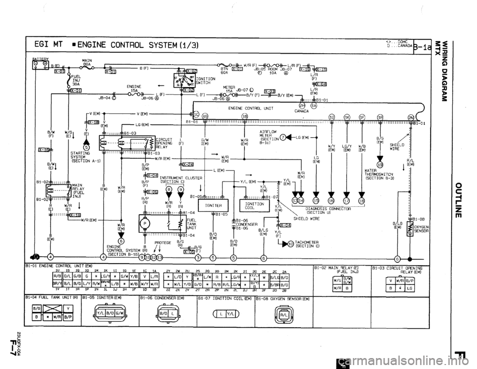
EGI MT n ENGINE CONTROL SYSTEM (i/3) CD.. OOHC 0 . ..CANAOA 3-l
MAIN
lOA @
HERMOSWITCW
SECTION B-3)
l-01 ENGINE CONTROL UNIT (EM)
iU 1s
IQ IO it4 1K 11 16 IE 1C ,A 61-02 MAIN RELAY (~1 2Y 2W 2U 25 28 20 2M 2K 21 26 2E 2C 24 81-03 CIRCUIT OPENING
(FUEL INJ)
R/0 O/L G/B G * -G/Y )c G/W Y/B
pL/W R
l -G/ x “y W 3/LG 0/O