power steering MAZDA 323 1992 Workshop Manual Suplement
[x] Cancel search | Manufacturer: MAZDA, Model Year: 1992, Model line: 323, Model: MAZDA 323 1992Pages: 279, PDF Size: 24.15 MB
Page 21 of 279

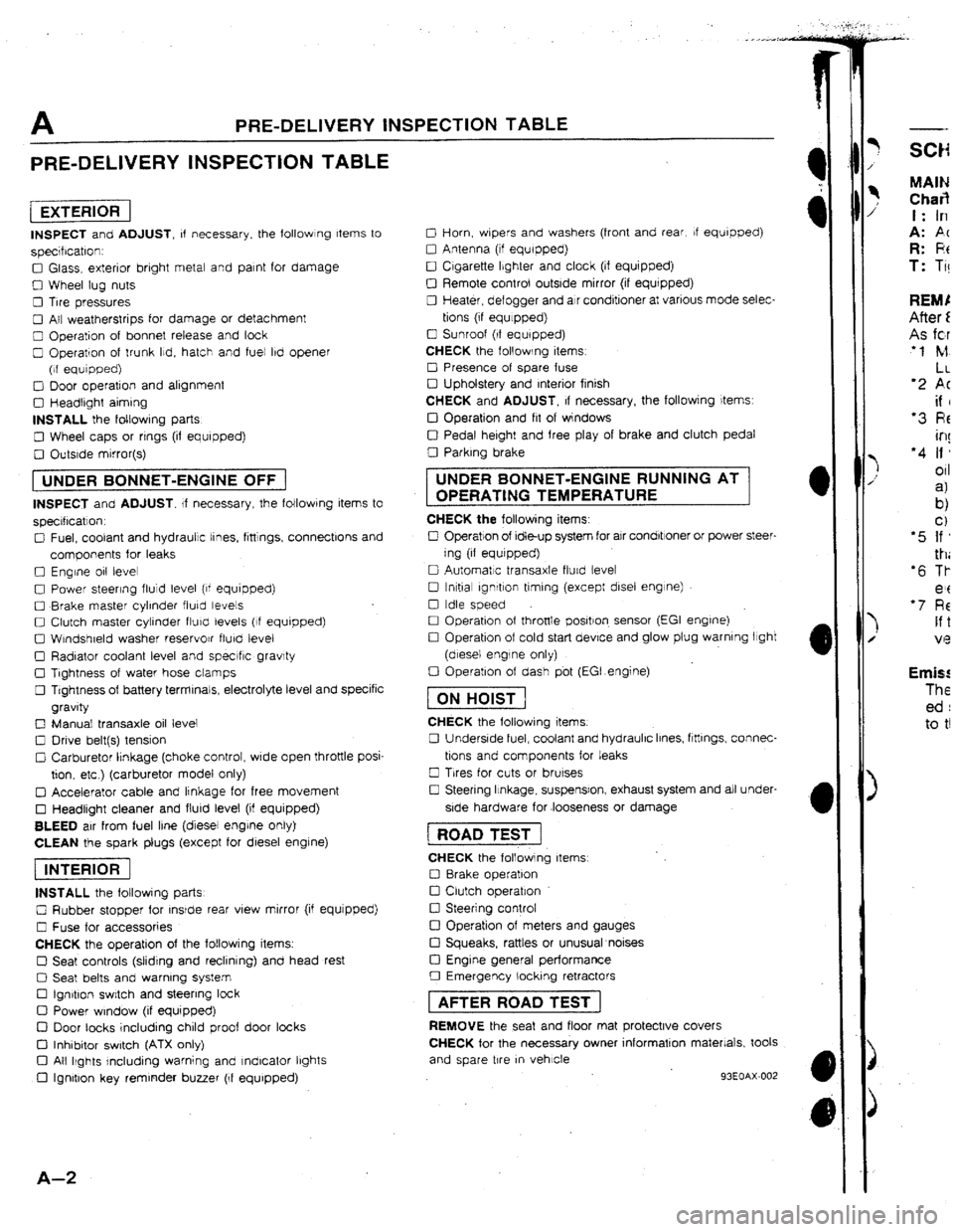
A PRE-DELIVERY INSPECTION TABLE
PRE-DELIVERY INSPECTION TABLE
[EXTERlORI
INSPECT and ADJUST, of necessary. the followlng Items to
specrfrcatron:
0 Glass, exterior bright metal and paint for damage
0 Wheel lug nuts
0 Tire pressures
0 All weatherstrips for damage or detachment
0 Operation of bonnet release and look
0 Operation of trunk Ild, hatch and fuel lbd opener
(of equipped)
0 Door operation and alignment
0 Headtrght aiming
INSTALL the foltowrng parts
0 Wheel caps or rrngs (if equipped)
0 Outsrde mirror(s)
1 UNDER BONNET-ENGINE OFF j
INSPECT and ADJUST. If necessary, the following items to
specrflcatlon.
0 Fuel, coolant and hydraulic tines, fittings, connectlons and
components for leaks
0 Engine 011 level
0 Power steering fluid level (of equipped)
0 Brake master cylinder fluky levels
0 Clutch master cylinder fturcl levels (If equipped)
0 Wtndshreld washer reservojr flurd level
0 Radiator coolant level and specrfic gravity
0 Tightness of water hose clamps
0 Tightness of battery terminals, electrolyte level and specific
gravity
0 Manual transaxle oil level
0 Drive belt(s) tension
Cl Carburetor lrnkage (choke control, wrde open throttle posi-
tion. etc ) (carburetor model only)
q Accelerator cable and linkage for free movement
0 Headlight cleaner and flurd level (if equipped)
BLEED air from fuel line (diesel engrne only)
CLEAN the spark plugs (except for diesel engine)
piEi6F]
INSTALL the following parts
0 Rubber stopper for rnsrde rear view mirror (if equjpped)
0 Fuse for accessories
CHECK the operation of the following items.
0 Seat controls (sliding and reclining) and head rest
0 Seat belts and warning system
Cl Ign&on switch and steering lock
0 Power window (if equipped)
D Door tacks including child proof door locks
Cl Inhibitor switch (ATX only)
Cl All Ikghts rncluding warning and Indicator lbghts
0 Ignition key reminder buzzer (If equipped)
A-Z
0 Horn, wbpers and washers (front and rear, If equipped)
0 Antenna (tf equipped)
0 Cigarette Ibghter and clock (if equipped)
0 Remote control outside mirror (if equrpped)
0 Heater, defogger and air conditioner at various mode selec-
tions (if equlppedj
0 Sunroof (If equipped)
CHECK the following items
0 Presence of spare fuse
0 Upholstery and Interior finish
CHECK and ADJUST, If necessary, the followjng items:
IJ Operation and fit of windows
0 Pedal height and free play of brake and clutch pedal
0 Parking brake UNDER BONNET-ENGINE RUNNING AT
OPERATING TEMPERATURE
CHECK the following items:
0 Operation of Idle-up system for air condbtroner or power steer-
ing (if equrpped)
0 Automatic transaxle flurd levet
0 tnltial ignrtlon timing (except disel engine)
0 Idle speed
0 Operation of throttle positron. sensor (EGI engrne)
0 Operation of cold start device and glow plug warning light
(diesel engine only)
0 Operation of dash pbt (EGI.engine)
fTiGGJ
CHECK the following items.
0 Underside fuel, coolant and hydraulic Irnes, ftttlngs, connec-
tions and components for leaks
0 Trres for cuts or brurses
0 Steering Itnkage, suspensron, exhaust system and all under-
side hardware for .looseness or damage 1 ROAD TEST j
CHECK the following items
0 8rake operation
0 Clutch operation
0 Steering control
!ZI Operation of meters and gauges
Cl Squeaks, rattles or unusual noises
Cl Engine general performance
0 Emergency locking retractors 1 AFTER ROAD TEST ]
REMOVE the seat and floor mat protective covers
CHECK for the necessary owner information materials, took
and spare tire
m vehicle
93EOAX-002
-- MAIN Char3 t: In
A: PC R: F!t T: Ti! Emis! The ed : to t!
Page 22 of 279

SCHEDULED MAINTENANCE SERVICES A
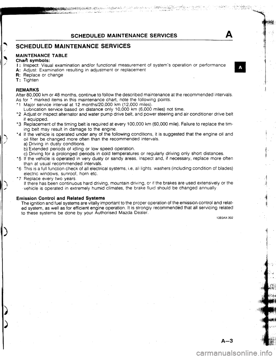
SCHEDULED MAINTENANCE SERVICES
MAINTENANCE TABLE
Chafi symbols:
1 : Inspect: Visual examination and/or functional measurement of system’s operation or
performance , A: Adjust: Examination resulting in adjustment or replacement
n
R: Replace or change
T: Tighten
REMARKS
After 80,000 km or 48 months, continue to follow the described maintenance at the recommended intervals.
As for * marked items in this maintenance chart, note the following points.
+ 1 Major service interval at 12 months/20,000 km (12,000 miles).
Lubrication service based on distance only 10,000 km (6,000 miles) not time.
l 2 Adjust or inspect alternator and water pump drive belt, and power steering and air conditioner drive belt
if equipped.
‘3 Replacement of the timing belt is required at every 100,000 km (60,000 mile). Failure to replace the tim-
ing bett may result in damage to the engine.
‘4 tf the vehicle is operated under any of the following conditions, it is suggested that the engine oil and
oil filter be changed more often than the recommended intervals.
a) Driving in dusty conditions. I
:
b) Extended periods of idling or low speed operation. i
i!
c) Driving for a prolonged periods in cold temperatures or regularly driving onty short distances.
*5 If the vehicle is operated in very dusty or sandy areas, inspect and, if necessary, replace more often
than at usual recommended intervals.
l 6 This IS a full function check of all electrical systems, i.e, atl
ltghts. washers (including condition of blades)
electric windows, sunroof, horn etc.
‘7 Replace every two years. $1
‘I
If there has been continuous hard driving, mountain
drivtng, or if the brakes are used extensively or the
vehicle is operated in extremely humid climates, the brake fluid should be changed annually.
Emission Control and Related Systems
The ignition and fuel systems are vitally important to the proper operation of the-emission control and relat-
ed system, as well as for efficient engine operation. It is strongly recommended that all servicing related
to these systems be done by your Authorised Mazda Dealer.
13EOAX-302 -4
I!
A-3
Page 111 of 279

N OUTLJNE
UUTLJNE
OUTLINE Of CONSTRUCTION
l EncJine speed sensing power steering (ESPS) is standard equipment for all models. The construction and
operation are basically the same as for previous models.
l The lock-to-lock specification of the steering wheel is reduced from 2.76 to 2.51.
13EONX-302
SPECIFICATIONS
hem Specifications
Steermg wheel Outer diameter mm {in] 370 { 14.57)
Lock-to-lock turns :i-‘~~:~.~~~~~~:~~;~~~~ :;‘:.. .‘:I .:::::.::~::::,:.:::.i: ,,,,.,:, :‘,:,,.:,: .,: I. . ..- :.~6:.n.:::;,:~~:~~~~~~~.~::~,:~:.: :: :
” .: ‘-.: .:.:::~:‘::.‘.::‘:‘:.I;:.‘,.: >.. .: :” 3 :. ,;:.+..i<.I. ‘_ : ; t:
. . ..: :: ::.:. .:::. ::r .;
. . . . . . . . . .y : :.: ,. .: ,_ : ., :
Me Collapsible
Steering shaft and joint Joint type
Tilt stroke
J 2-cross joint
mm {in] 30 11.18)
Type Rack-and-pinion
I
Steering gear Gear ratio
Rack stroke mm [in] 00 (infinite)
121 f4.761
Capacity
Power steertng fluid 1 (US qt Imp qt) 018 (0.85, 0.701
We ATF DexrorPlI or M-ID
,
Shaded area rndicates new specrfcatlon. t3EONX-303
N-2
Page 173 of 279

‘T 1 SPECIAL TOOLS
STEERING
rONT AND REAR AXLES (CUNT’D)
3 FO27 005
ttachment @62
9 F027 009
ttachment
68 and $77
9 Vool 795
staller. ort seal
9 BOO1 795
xtafter, oil seal 3 HO02 671
dapter
bwer steer1
9 8032 3ti
lemover ,
rearing & oI
Power steer
19 B032 3’
‘m3ctor trc
d seal
--
3 B032 3t
older, pot
leering pu
‘ower stt:c
--
9 8032 3
Votector ,
her bw
--
$9 8032 :
Mench, r
[Power stl
-- TOOL NUMBER
& DESCRIPTION PRiORlTY
ILLUSTRATION
49 HO34 201
Support blczk
49 HO27 002
Remover, bearing
49 F026 103
Puller, wheel hub
49 F026 102
Installer, bearing A
fEERING
I’OdL NUMBER
L DESCRIPTION PRIORITY ILLUSTRATION
PRIORITY ) ILLUSTRATION TOOL NUMBER
& DESCRlPTtON
49 GO33 108 19 0180 510B
Utachment
Ireload B
Adapter, caster
camber gauge A
19 8032
adapter
,Power 31
--
49 GO32
House
power 5 49 HO32 301 $9 0118 850C
Uler, ball joint
I A Wrench
(Power steering)
49 1232 670A
Gauge set,
power steering 49 1243 785
installer.
dust boot A
Page 174 of 279

SPECIAL TOOLS ST
STEERING (CONT’D)
PRIORITY TOOL NUMBER
et QESCRlPTlUN ILLUSTRATION
19 HO02 671
4dapter
Power steering) A
(Power steering)
(Power steering)
49 6032 3t2
(Power steering)
49 6032 323
Remover body,
rod seal
49 8032 316
Support block,
PM
(Power steering)
49 B032..327
Wrench,
outer box
49 9032 315
Installer, oil seal A
(Power steering)
0
19 8032 317
qemover ,
Dearing & oil seal
:Power steermg) B
49 8032 324
Protector body,
rod seal A
49 8032 305
Holder, power
steering pump
(Power steermg) A
49 8032 326
Protector,
outer box A
49 8032 306
Wrench, plug
(Power steermg) A
49 8032 321
Adapter
(Power steering) A
A
n
49 GO32 317
House (Power steering)
ST-7
Page 175 of 279

ST SPECIAL TOOLS --
BRAKIN
STEERING (CONT’D)
--
TOOL fi
h DESC
--
19 1285
Wer,
Qeedle :
--
49 8065
Harness;
--
49 cw:
Setting
retainer
--
49 804
Socke: PRIORITY / ILLUSTRATJUN TOOL NUMBER
& DEScCRIPTION TOOL NUMBER
& DESCRIPTION PRlORITY
ILLUSTRATION
A
(IlIP
A
0
A
c!iz9 49 B032 310
49 8032 320
0
Wrench
A
(Power steermg)
jq
49 F032 303
Handle
(Power steering)
Protector, pmon seal
(Power steermg)
49 B032 311
Protector,
Jipper seat
(Power steering)
49 8032 325
Guide. rod seal
BRAKING
PRIORITY
ILLUSTRATION TOOL NUMBER
b DESCRlPTlON TOOL NUMSER
& DESCRIPTION PRIORITY
ILLUSTRATION
49 8043 001
Adjust gauge
I A 49 0259 770B
Wrench, flare nut
A
49 0221 60X
Expand tool,
disc brake 49 8043 002
Installer, bearing A
TOOL
& DES
--
49 BC:
Replac
rubber
InstallE
dust 3 49 0208 701A
Atr out tool, boot 49 8043 003
Turning, lock tool A
49 FAt8 602
49 U043 OAO
I
Gauge set,
I A
oil pressure Wrench ,disc
brake piston
Page 185 of 279

GI Reading Wiring Diagrams
System circuit diagram/connector diagram
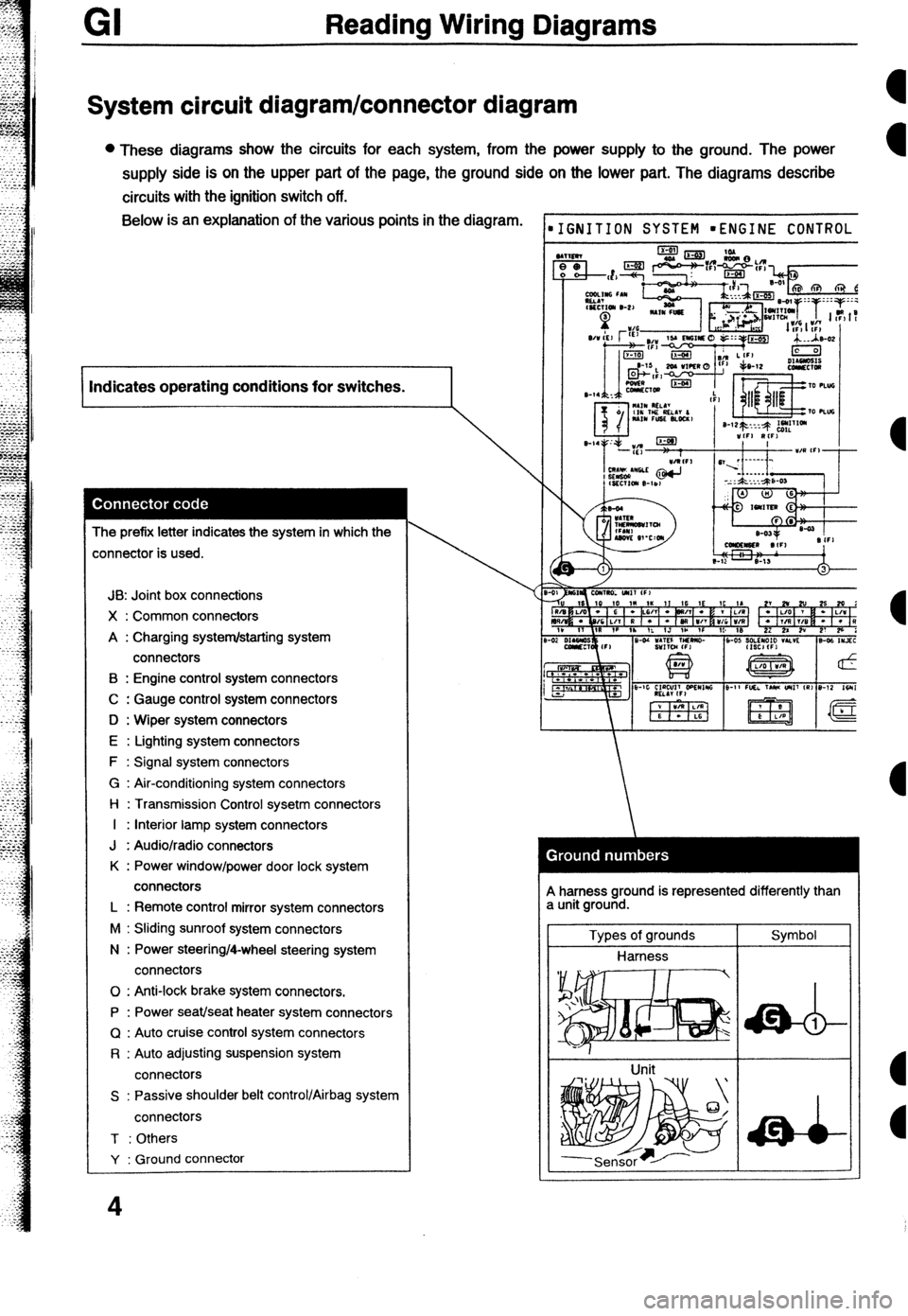
l These diagrams show the circuits for each system, from the power supply to the ground. The power
supply side is on the upper part of the page, the ground side on the lower part. The diagrams describe
circuits with the ignition switch off. Below is an explanation of the various points in the diagram.
I Indicates operating conditions for switches.
I
The prefix letter indicates the system in which the
:onnector is used.
JB: Joint box connections
X : Common connectors
A : Charging system/starting system
connectors
B : Engine control system connectors
C : Gauge control system connectors
D : Wiper system connectors
E : Lighting system connectors
F : Signal system connectors
G : Air-conditioning system connectors
l-l : Transmission Control sysetm connectors
I : Interior lamp system connectors
J : Audio/radio connectors
K : Power window/power door lock system
connectors
L : Remote control mirror system connectors
M : Sliding sunroof system connectors
N : Power steering/4-wheel steering system
connectors
0 : Anti-lock brake system connectors.
P : Power seat/seat heater system connectors
Q : Auto cruise control system connectors
R : Auto adjusting suspension system
connectors
S : Passive shoulder belt control/Airbag system
connectors
T : Others
Y : Ground connector
4
IGNITION SYSTEM mENGINE CONTROL
A harness ground is represented differently than
a unit ground.
Types of grounds
Harness
Unit Symbol
Page 191 of 279

Reading Wiring Diagrams
Loaic symbols I
ypes of logic symbols Operation Expressing output Simple relay circuits
OR
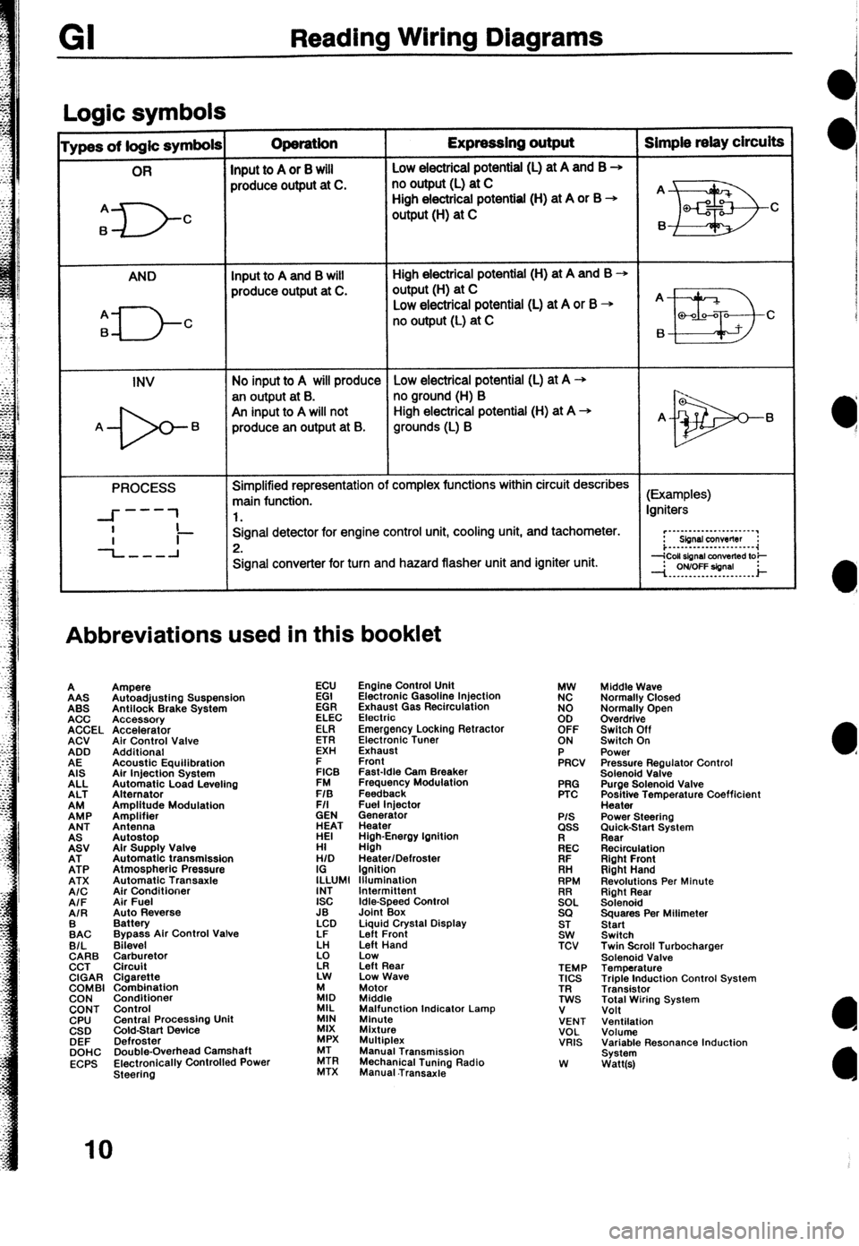
Input to A or 8 will Low electricai potential (L) at A and B +
produce output at C. no output (L) at C
A
6
D- High electrical potential (H) at A or B +
C output (H) at C
AND Input to A and B will High electrical potential (H) at A and B +
produce output at C. output(H) at C
q---J-c
Low electrical potential (L) at A or B + A
no output (L) at C
B a-00-a C
6
INV No input to A will produce Low electrical potential (L) at A -+
an output at B. no ground (H) B
An input to A will not High electrical potential (H) at A +
A- 6 produce an output at B. grounds (L) B A- 6
PROCESS Simplified representation of complex functions within circuit describes
main function. (Examples)
---
--I- 1 1. Igniters
I
-L-l Signal detector for engine control unit, cooling unit, and tachometer.
Ii- 2. r”~“-‘-‘-““‘~~‘.“’
Sbnsl conwflw :
i...-..--.---......-.~~
Signal converter for turn and hazard flasher unit and igniter unit.
Abbreviations used in this booklet
A
AAS
ABS
ACC
ACCEL
ACV
ADD
AE
AIS
ALL
ALT
EP
ANT
EV
EP
ATX
A/C
AIF
AIR
:AC
B/L
CARB
CCT
CIGAR
COMBI
CON
CONT
CPU
CSD
DEF
DOHC
ECPS Ampere
Autoadjusting Suspension
Antilock Brake System
Accessory
Accelerator
Air Control Valve
Additional
Acoustic Equilibration
Air Injection System
Automatic Load Leveling
Alternator
Amplitude Modulation
Amplifier
Antenna
Autostop
Alr Supply Valve
Automatic transmission
Atmospheric Pressure
Automatic Transaxle
Air Conditioner
Air Fuel
Auto Reverse
Battery
Bypass Air Control Valve
Bilevel
$rr$:,tor
Cigarette
Combination
Conditioner
Control
Central Procassino Unit
&Id-Start Device -
Defroster
Double-Overhead Camshaft
Electronically Controlled Power
Steering ECU
EGI
EGR
ELEC
ELR
ETR
EXH
E
FICB
FM
F/S
F/I
GEN
ET
HI
H/D
I;LUMl
INT
ISC
JB
LCD
LF
k!
z Engine Control Unit
Electronic Gasoline Injection
Exhaust Gas Recirculation
Electrio
Emergency Locking Retractor
Electronic Tuner
Exhaust
Front
Fast-Idle Cam Breaker
Frequency Modulation
Feedback
Fuel lniector
Generator
Heater
High-Energy Ignition
High
Heater/Defroster
Ignition
lllumlnation
Idle-Speed Control
Joint Box
Liquid Crystal Display
Left Front
Left Hand
Low
Left Rear
Low Wave
:I, Motor
Middle
MIL
MIN Malfunction Indicator Lamp
Minute
MIX
Mixture
MPX Multiplex
ZR Manual Transmission
MTX Mechanical Tuning Radio
Manual .Transaxie PRG
PTC
P/S ass
kc
FIF
. . .
RH
RPM
!2EL
SQ
ST
SW
TCV
TEMP
TICS
TR
TWS
V
VENT
VOL
VRIS
W Middle Wave
Normally Closed
Normally Open
Overdrive
Switch Off
Switch On
Power
Pressure Regulator Control
Solenoid Valve
Purge Solenoid Valve
Positive Temperature Coefficient
Heater
Power Steering
;im&k-Start System
Recirculation
Right Front
Right Hand
Revolutions Per Minute
Right Rear
Solenoid
Squares Per Milimeter
Start
Switch
Twin Scroll Turbocharger
Solenoid Valve
Temperature
Triple Induction Control System
Transistor
Total Wiring System
Volt
Ventilation
Volume
Variable Resonance Induction
System
Watt(s)
IO
Page 213 of 279

-” ‘ENGINE CONTROL SYSTEM (3/3)
FRM\IT FOG LIGHT RELAY REAR WINDOW
INsTF%+ffNT CLUSTER BLOWER
SWITCH
(SECTION G1
B/O B/O E/LG B/BA L/Y t
(EM) (EM) (EMI (EM)
I
%P
:;~~~=====~::~~~~=~~=~~
POWER STEERING
PRESSURE SWITCH
8
2-01 ENGINE CONTROL UNIT (EM) El-10 POWER STEERING PRESSURE SWITCH(F)
I” IS 10 ID 1M IK iI IG IE 1C ,A 2Y 2W 2U 25 20 20 2H 2K 21 26 2E
2C 2A
R/B O/L G/B G * -G/Y L G/W * v L/R LG L/O Y R/Y L/W R -G/d-G/F * Y/L P/B 3/LG B/O
BR/ B/L B/G L/Y R/W * L/B O/B W/B W/Y W/R G W/L Y/B G/O W R/B R/L G/R R/Y * x B/BqE/O
1” ,T
IR II’ 1N IL 1.J 1H 1F 10 16 2X 2V 2T 2R 2P 2N 2L 2J 2H 2F 2D 28
1-20 AIRFLOW METER (EM) 81-21 THROTTLE SE%;; 81-22 CLUTCH SWITCH (F) 81-23 NEUTRAL SWITCH (EM)
ii
32
Page 277 of 279

a
l
a
.Sc+wCi!J VALVE(PRC HIGH TEMp)
R THERMOSENSOR
POWER STEERING P
ABS WHEEL
SPEED SENSOR Rk
OXYGEN &OR
RUNNlNG LIGHT RELAY No.2
RUNNINGLIGMR
PavERDooR
HEADLIGHT RELAY
ENGINE CONTROL UNIT
STOPUGHT SWITCH
HORN RELAY SEAT WARMER RELAY