camshaft position sensor MAZDA 6 2002 Workshop Manual Suplement
[x] Cancel search | Manufacturer: MAZDA, Model Year: 2002, Model line: 6, Model: MAZDA 6 2002Pages: 909, PDF Size: 17.16 MB
Page 8 of 909

NEW STANDARDS
GI–5
GINEW STANDARDS TABLEA6E202800020201•The following is a comparison of the previous standard and the new standard.
NEW STANDARDS
New Standard Previous Standard
Remark
Abbrevi-
ationNameAbbrevi-
ationName
AP Accelerator Pedal—Accelerator Pedal
ACL Air Cleaner—Air Cleaner
A/C Air Conditioning—Air Conditioning
BARO Barometric Pressure—Atmospheric Pressure
B+ Battery Positive VoltageV
BBattery Voltage
—Brake Switch—Stoplight Switch
—Calibration Resistor—Corrected Resistance #6
CMP sensor Camshaft Position Sensor—Crank Angle Sensor
CAC Charge Air Cooler—Intercooler
CLS Closed Loop System—Feedback System
CTP Closed Throttle Position—Fully Closed
—Closed Throttle Position Switch—Idle Switch
CPP Clutch Pedal Position—Clutch Position
CIS Continuous Fuel Injection System EGI Electronic Gasoline Injection System
CS sensor Control Sleeve Sensor CSP sensor Control Sleeve Position Sensor #6
CKP sensor Crankshaft Position Sensor—Crank Angle Sensor 2
DLC Data Link Connector—Diagnosis Connector
DTM Diagnostic Test Mode—Test Mode #1
DTC Diagnostic Trouble Code—Service Code(s)
DI Distributor Ignition—Spark Ignition
DLI Distributorless Ignition—Direct Ignition
EI Electronic Ignition—Electronic Spark Ignition #2
ECT Engine Coolant Temperature—Water Thermo
EM Engine Modification—Engine Modification
—Engine Speed Input Signal—Engine RPM Signal
EVAP Evaporative Emission—Evaporative Emission
EGR Exhaust Gas Recirculation—Exhaust Gas Recirculation
FC Fan Control—Fan Control
FF Flexible Fuel—Flexible Fuel
4GR Fourth Gear—Overdrive
—Fuel Pump Relay—Circuit Opening Relay #3
FSO
solenoidFuel Shut Off Solenoid FCV Fuel Cut Valve #6
GEN Generator—Alternator
GND Ground—Ground/Earth
HO2S Heated Oxygen Sensor—Oxygen Sensor With heater
IAC Idle Air Control—Idle Speed Control
—IDM Relay—Spill Valve Relay #6
—Incorrect Gear Ratio——
—Injection Pump FIP Fuel Injection Pump #6
—Input/Turbine Speed Sensor—Pulse Generator
IAT Intake Air Temperature—Intake Air Thermo
KS Knock Sensor—Knock Sensor
MIL Malfunction Indicator Lamp—Malfunction Indicator Light
MAP Manifold Absolute Pressure—Intake Air Pressure
MAF sensor Mass Air Flow Sensor—Airflow Sensor
MFI Multiport Fuel Injection—Multiport Fuel Injection
OBD On Board Diagnostic—Diagnosis/Self Diagnosis
Page 42 of 909
TIMING BELT
B2–11
B2
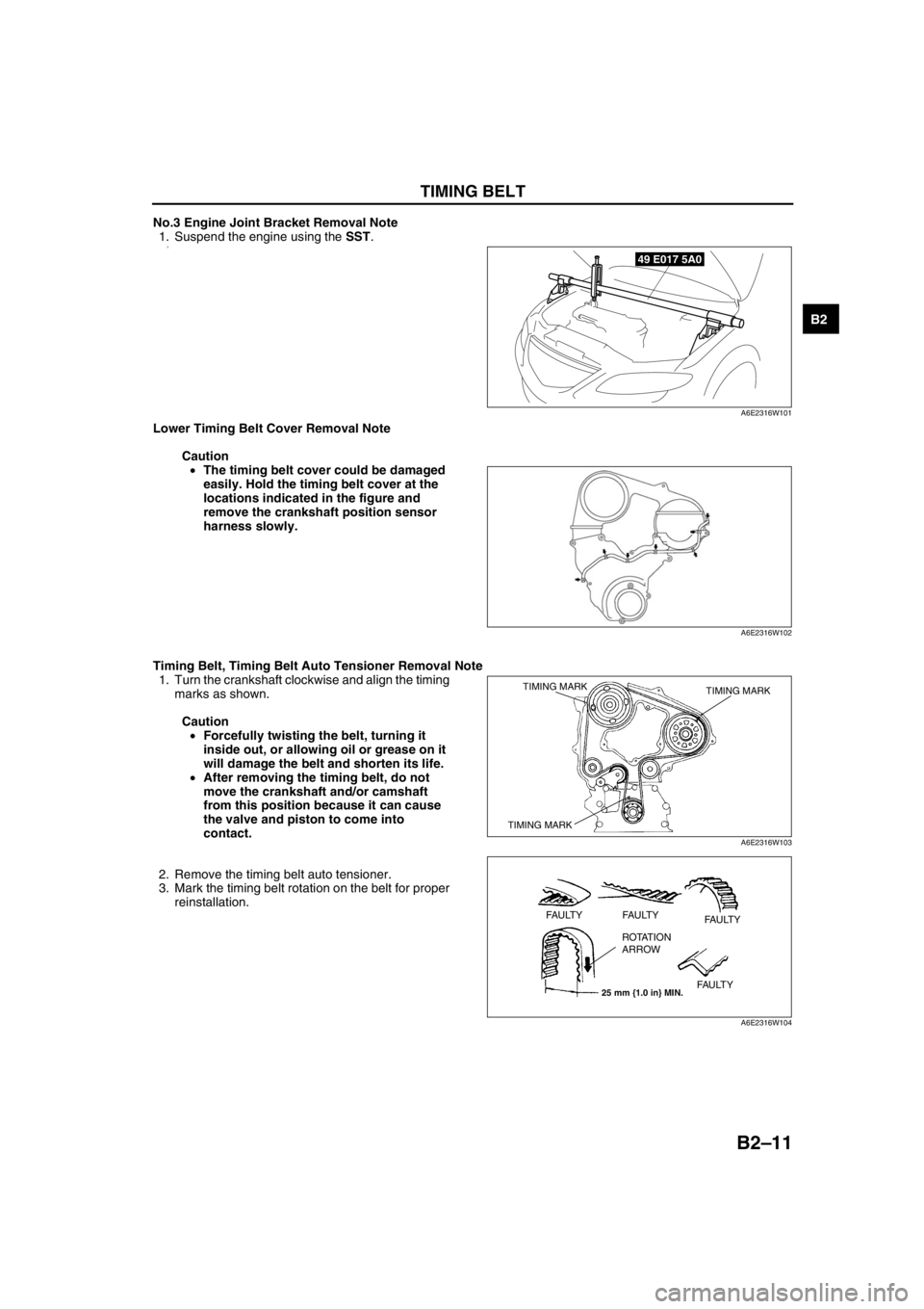
No.3 Engine Joint Bracket Removal Note
1. Suspend the engine using the SST.
2.
Lower Timing Belt Cover Removal Note
Caution
•The timing belt cover could be damaged
easily. Hold the timing belt cover at the
locations indicated in the figure and
remove the crankshaft position sensor
harness slowly.
Timing Belt, Timing Belt Auto Tensioner Removal Note
1. Turn the crankshaft clockwise and align the timing
marks as shown.
Caution
•Forcefully twisting the belt, turning it
inside out, or allowing oil or grease on it
will damage the belt and shorten its life.
•After removing the timing belt, do not
move the crankshaft and/or camshaft
from this position because it can cause
the valve and piston to come into
contact.
2. Remove the timing belt auto tensioner.
3. Mark the timing belt rotation on the belt for proper
reinstallation.
49 E017 5A0
A6E2316W101
A6E2316W102
TIMING MARK TIMING MARK
TIMING MARK
A6E2316W103
25 mm {1.0 in} MIN.
FAULTY FAULTY
FAULTY
FAULTY ROTATION
ARROW
A6E2316W104
Page 154 of 909
F2–2
MASS AIR FLOW (MAF)/INTAKE AIR
TEMPERATURE (IAT) SENSOR
INSPECTION ................................................ F2-74
INTAKE AIR TEMPERATURE (IAT)
SENSOR NO.2 INSPECTION....................... F2-75
ENGINE COOLANT TEMPERATURE (ECT)
SENSOR REMOVAL/INSTALLATION .......... F2-76
ENGINE COOLANT TEMPERATURE (ECT)
SENSOR INSPECTION ................................ F2-76
FUEL TEMPERATURE SENSOR
INSPECTION ................................................ F2-77
BOOST SENSOR INSPECTION ..................... F2-78
FUEL PRESSURE SENSOR INSPECTION .... F2-79
CAMSHAFT POSITION (CMP) SENSOR
REMOVAL/INSTALLATION .......................... F2-80
CAMSHAFT POSITION (CMP) SENSOR
INSPECTION ................................................ F2-80
CRANKSHAFT POSITION (CKP) SENSOR
REMOVAL/INSTALLATION .......................... F2-81
CRANKSHAFT POSITION (CKP) SENSOR
INSPECTION ................................................ F2-82
CALIBRATION RESISTOR INSPECTION ....... F2-83
INJECTOR DRIVER MODULE (IDM)
INSPECTION ................................................ F2-84
ON-BOARD DIAGNOSTIC................................. F2-85
ON-BOARD DIAGNOSTIC TEST .................... F2-85
DTC CONFIRMATION PROCEDURE ............. F2-85
KOEO/KOER SELF-TEST PROCEDURE ....... F2-86
AFTER REPAIR PROCEDURE ....................... F2-86
DTC TABLE ..................................................... F2-87
DTC P0016 ...................................................... F2-88
DTC P0088 ...................................................... F2-89
DTC P0091 ...................................................... F2-90
DTC P0092 ...................................................... F2-92
DTC P0093 ...................................................... F2-94
DTC P0097 ...................................................... F2-95
DTC P0098 ...................................................... F2-97
DTC P0102 ...................................................... F2-99
DTC P0103 .................................................... F2-101
DTC P0107 .................................................... F2-103
DTC P0108 .................................................... F2-105
DTC P0112 .................................................... F2-107
DTC P0113 .................................................... F2-109
DTC P0117 .................................................... F2-111
DTC P0118 .................................................... F2-113
DTC P0121 .................................................... F2-115
DTC P0122 .................................................... F2-116
DTC P0123 .................................................... F2-118
DTC P0182 .................................................... F2-120
DTC P0183 .................................................... F2-122
DTC P0191 .................................................... F2-124
DTC P0192 .................................................... F2-125
DTC P0193 .................................................... F2-127
DTC P0200 .................................................... F2-129
DTC P0221 .................................................... F2-131
DTC P0222 .................................................... F2-132
DTC P0223 .................................................... F2-134
DTC P0300 .................................................... F2-136
DTC P0336 .................................................... F2-137
DTC P0337 .................................................... F2-138
DTC P0341 .................................................... F2-140
DTC P0342 .................................................... F2-141
DTC P0380 .................................................... F2-143
DTC P0504 .................................................... F2-145
DTC P0510 .................................................... F2-148
DTC P0512 .................................................... F2-150
DTC P0564 .................................................... F2-152
DTC P0602 .................................................... F2-154DTC P0606..................................................... F2-155
DTC P0610..................................................... F2-155
DTC P0661..................................................... F2-156
DTC P0662..................................................... F2-158
DTC P0850..................................................... F2-160
DTC P1190..................................................... F2-162
DTC P2228..................................................... F2-164
DTC P2229..................................................... F2-164
TROUBLESHOOTING...................................... F2-165
SYMPTOM DIAGNOSTIC INDEX .................. F2-165
SYMPTOM QUICK DIAGNOSIS CHART ...... F2-167
NO.1 MELTING OF MAIN OR
OTHER FUSES ........................................... F2-173
NO.2 MIL ILLUMINATES ............................... F2-174
NO.3 WILL NOT CRANK ............................... F2-174
NO.4 HARD START/LONG CRANK/ERRATIC
START/ERRATIC CRANK .......................... F2-176
NO.5 ENGINE STALLS-AFTER
START/AT IDLE .......................................... F2-178
NO.6 CRANKS NORMALLY BUT WILL NOT
START ........................................................ F2-181
NO.7 SLOW RETURN TO IDLE .................... F2-184
NO.8 ENGINE RUNS ROUGH/ROLLING
IDLE ............................................................ F2-186
NO.9 FAST IDLE/RUNS ON .......................... F2-189
NO.10 LOW IDLE/STALLS DURING
DECELERATION ........................................ F2-190
NO.11 ENGINE STALLS/QUITS, ENGINE RUNS
ROUGH, MISSES, BUCK/JERK,
HESITATION/STUMBLE, SURGES ........... F2-192
NO.12 LACK/LOSS OF
POWER-ACCELERATION/CRUISE ........... F2-195
NO.13 KNOCKING/PINGING......................... F2-199
NO.14 POOR FUEL ECONOMY.................... F2-202
NO.15 EMISSION COMPLIANCE.................. F2-205
NO.16 HIGH OIL
CONSUMPTION/LEAKAGE ....................... F2-209
NO.17 COOLING SYSTEM
CONCERNS-OVERHEATING .................... F2-210
NO.18 COOLING SYSTEM
CONCERNS-RUNS COLD ......................... F2-212
NO.19 EXCESSIVE BLACK SMOKE ............. F2-213
NO.20 FUEL ODOR
(IN ENGINE COMPARTMENT) .................. F2-216
NO.21 ENGINE NOISE .................................. F2-217
NO.22 VIBRATION CONCERNS (ENGINE) .. F2-220
NO.23 A/C DOES NOT WORK
SUFFICIENTLY ........................................... F2-222
NO.24 A/C ALWAYS ON OR A/C
COMPRESSOR RUNS
CONTINUOUSLY........................................ F2-223
NO.25 A/C DOES NOT CUT OFF UNDER
WIDE OPEN THROTTLE CONDITIONS .... F2-224
NO.26 CONSTANT VOLTAGE ...................... F2-225
INTERMITTENT CONCERN
TROUBLESHOOTING ................................ F2-227
ENGINE CONTROL SYSTEM
OPERATION INSPECTION ........................ F2-229
Page 176 of 909
F2–24
CONTROL SYSTEM, ON-BOARD DIAGNOSTIC
CONTROLLER AREA NETWORK (CAN)A6E404018881206Outline
•The PCM transmit/received the information other units using CAN to simplify the system.
Transmit Information
•Engine speed
•Vehicle speed
•Accelerator pedal position
•Fuel injection information
•Torque reduction inhibit
•Intake air temperature
•Engine coolant temperature
•Travelled distance
•Glow indicator light conditions
•Engine displacement
•Number of cylinders
•Air induction type
•Fuel type and delivery
•Country
•Transmission/axle type
•Tire circumference (front/rear)
•Cruise main indicator light conditions
•Cruise set indicator light conditions
Received Information
•Torque reduction request from DSC HU/CM
•Wheel speed from ABS HU/CM or DSC HU/CM
—Front left
—Front right
•Travelled distance from ABS HU/CM or DSC HU/CM
End Of Sie
OUTLINEA6E407018881201•The on-board diagnostic system is essentially carried over from that of the current MPV (LW) MZR-CD (RF
Turbo) engine models, except for the following. (See MPV Workshop Manual Supplement 1737-1*-02C.)
—DTCs, PID monitoring items, and simulation items have been changed.
—KOEO/KOER self-test items have been changed.
End Of Sie
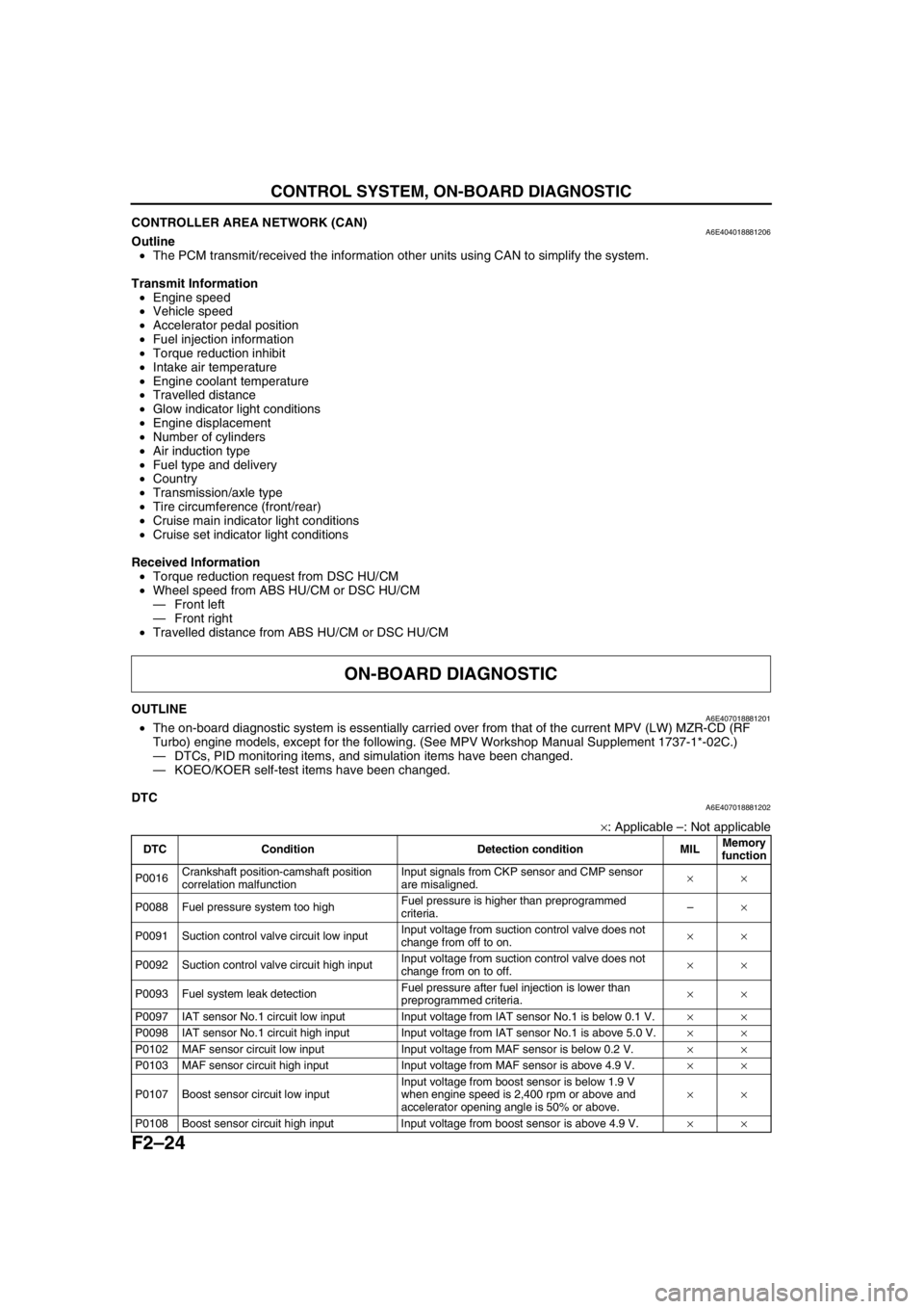
DTCA6E407018881202
×: Applicable –: Not applicable
ON-BOARD DIAGNOSTIC
DTC Condition Detection condition MILMemory
function
P0016Crankshaft position-camshaft position
correlation malfunctionInput signals from CKP sensor and CMP sensor
are misaligned.××
P0088 Fuel pressure system too highFuel pressure is higher than preprogrammed
criteria.–×
P0091 Suction control valve circuit low inputInput voltage from suction control valve does not
change from off to on.××
P0092 Suction control valve circuit high inputInput voltage from suction control valve does not
change from on to off.××
P0093 Fuel system leak detectionFuel pressure after fuel injection is lower than
preprogrammed criteria.××
P0097 IAT sensor No.1 circuit low input Input voltage from IAT sensor No.1 is below 0.1 V.××
P0098 IAT sensor No.1 circuit high input Input voltage from IAT sensor No.1 is above 5.0 V.××
P0102 MAF sensor circuit low input Input voltage from MAF sensor is below 0.2 V.××
P0103 MAF sensor circuit high input Input voltage from MAF sensor is above 4.9 V.××
P0107 Boost sensor circuit low inputInput voltage from boost sensor is below 1.9 V
when engine speed is 2,400 rpm or above and
accelerator opening angle is 50% or above.××
P0108 Boost sensor circuit high input Input voltage from boost sensor is above 4.9 V.××
Page 185 of 909
LOCATION INDEX
F2–33
F2
End Of Sie
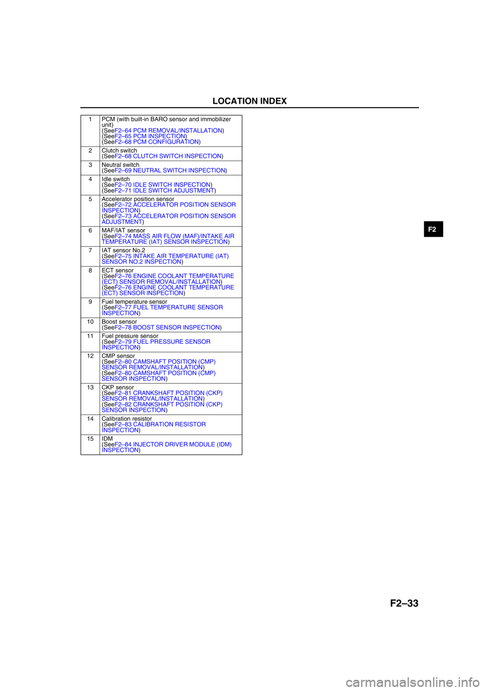
1 PCM (with built-in BARO sensor and immobilizer
unit)
(SeeF2–64 PCM REMOVAL/INSTALLATION)
(SeeF2–65 PCM INSPECTION)
(SeeF2–68 PCM CONFIGURATION)
2 Clutch switch
(SeeF2–68 CLUTCH SWITCH INSPECTION)
3 Neutral switch
(SeeF2–69 NEUTRAL SWITCH INSPECTION)
4 Idle switch
(SeeF2–70 IDLE SWITCH INSPECTION)
(SeeF2–71 IDLE SWITCH ADJUSTMENT)
5 Accelerator position sensor
(SeeF2–72 ACCELERATOR POSITION SENSOR
INSPECTION)
(SeeF2–73 ACCELERATOR POSITION SENSOR
ADJUSTMENT)
6 MAF/IAT sensor
(SeeF2–74 MASS AIR FLOW (MAF)/INTAKE AIR
TEMPERATURE (IAT) SENSOR INSPECTION)
7 IAT sensor No.2
(SeeF2–75 INTAKE AIR TEMPERATURE (IAT)
SENSOR NO.2 INSPECTION)
8ECT sensor
(SeeF2–76 ENGINE COOLANT TEMPERATURE
(ECT) SENSOR REMOVAL/INSTALLATION)
(SeeF2–76 ENGINE COOLANT TEMPERATURE
(ECT) SENSOR INSPECTION)
9 Fuel temperature sensor
(SeeF2–77 FUEL TEMPERATURE SENSOR
INSPECTION)
10 Boost sensor
(SeeF2–78 BOOST SENSOR INSPECTION)
11 Fuel pressure sensor
(SeeF2–79 FUEL PRESSURE SENSOR
INSPECTION)
12 CMP sensor
(SeeF2–80 CAMSHAFT POSITION (CMP)
SENSOR REMOVAL/INSTALLATION)
(SeeF2–80 CAMSHAFT POSITION (CMP)
SENSOR INSPECTION)
13 CKP sensor
(SeeF2–81 CRANKSHAFT POSITION (CKP)
SENSOR REMOVAL/INSTALLATION)
(SeeF2–82 CRANKSHAFT POSITION (CKP)
SENSOR INSPECTION)
14 Calibration resistor
(SeeF2–83 CALIBRATION RESISTOR
INSPECTION)
15 IDM
(SeeF2–84 INJECTOR DRIVER MODULE (IDM)
INSPECTION)
Page 218 of 909
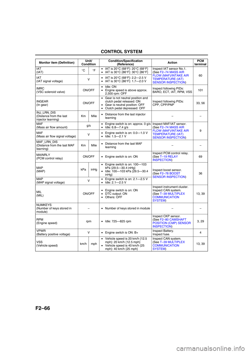
F2–66
CONTROL SYSTEM
IAT
(IAT)°C°F•IAT is 20°C {68°F}: 20°C {68°F}
•IAT is 30°C {86°F}: 30°C {86°F}Inspect IAT sensor No.1.
(See F2–74 MASS AIR
FLOW (MAF)/INTAKE AIR
TEMPERATURE (IAT)
SENSOR INSPECTION)60
IAT
(IAT signal voltage)V•IAT is 20°C {68°F}: 2.2—2.5 V
•IAT is 30°C {86°F}: 1.7—2.0 V
IMRC
(VSC solenoid valve)ON/OFF•Idle: ON
•Engine speed is above approx.
2,500 rpm: OFFInspect following PIDs:
BARO, ECT, IAT, RPM, VSS101
INGEAR
(In gear)ON/OFF•Gear is not neutral position and
clutch pedal released: ON
•Gear is neutral position: OFF
•Clutch pedal depressed: OFFInspect following PIDs:
CPP, CPP/PNP33, 56
INJ_LRN_DIS
(Distance from the last
injector learning)Km Mile•Distance from the last injector
learning––
MAF
(Mass air flow amount)g/s•Engine switch is on: approx. 0 g/s
•Idle: 6.8—7.4 g/sInspect MAF/IAT sensor.
(See F2–74 MASS AIR
FLOW (MAF)/INTAKE AIR
TEMPERATURE (IAT)
SENSOR INSPECTION)9
MAF
(Mass air flow signal voltage)V•Engine switch is on: 0.0—1.0 V
•Idle: 1.5—2.1 V
MAF_LRN_DIS
(Distance from the last MAF
learning)Km Mile•Distance from the last MAF
learning––
MAINRLY
(PCM control relay)ON/OFF•Engine switch is on: ONInspect PCM control relay.
(See T–19 RELAY
INSPECTION)69
MAP
(MAP)kPa inHg•Engine switch is on: 100—103
kPa {29.5—30.4 inHg}
•Idle: 100—103 kPa {29.5—30.4
inHg}Inspect boost sensor.
(See F2–78 BOOST
SENSOR INSPECTION)36
MAP
(MAP signal voltage)V•Engine switch is on: 2.1—2.5 V
•Idle: 2.1—2.5 V
MIL
(MIL)ON/OFF•Engine switch is on: ON
•DTC output: ON
•Others: OFFInspect instrument cluster.
Inspect CAN system.
(See T–39 MULTIPLEX
COMMUNICATION
SYSTEM)13, 39
NUMKEYS
(Number of keys stored in
module)–•Number of keys stored in module––
RPM
(Engine speed)rpm•Idle: 725—825 rpmInspect CKP sensor.
(See F2–80 CAMSHAFT
POSITION (CMP) SENSOR
INSPECTION)3, 29
VPWR
(Battery positive voltage)V•Engine switch is ON: B+Inspect Battery.
Inspect fuse.4
VSS
(Vehicle speed)km/h mph•Vehicle speed is 20 km/h {12.5
mph}: 20 km/h {12.5 mph}
•Vehicle speed is 40 km/h {25
mph}: 40 km/h {25 mph}Inspect CAN system.
(See T–39 MULTIPLEX
COMMUNICATION
SYSTEM)13, 39 Monitor item (Definition)Unit/
ConditionCondition/Specification
(Reference)ActionPCM
terminal
Page 232 of 909
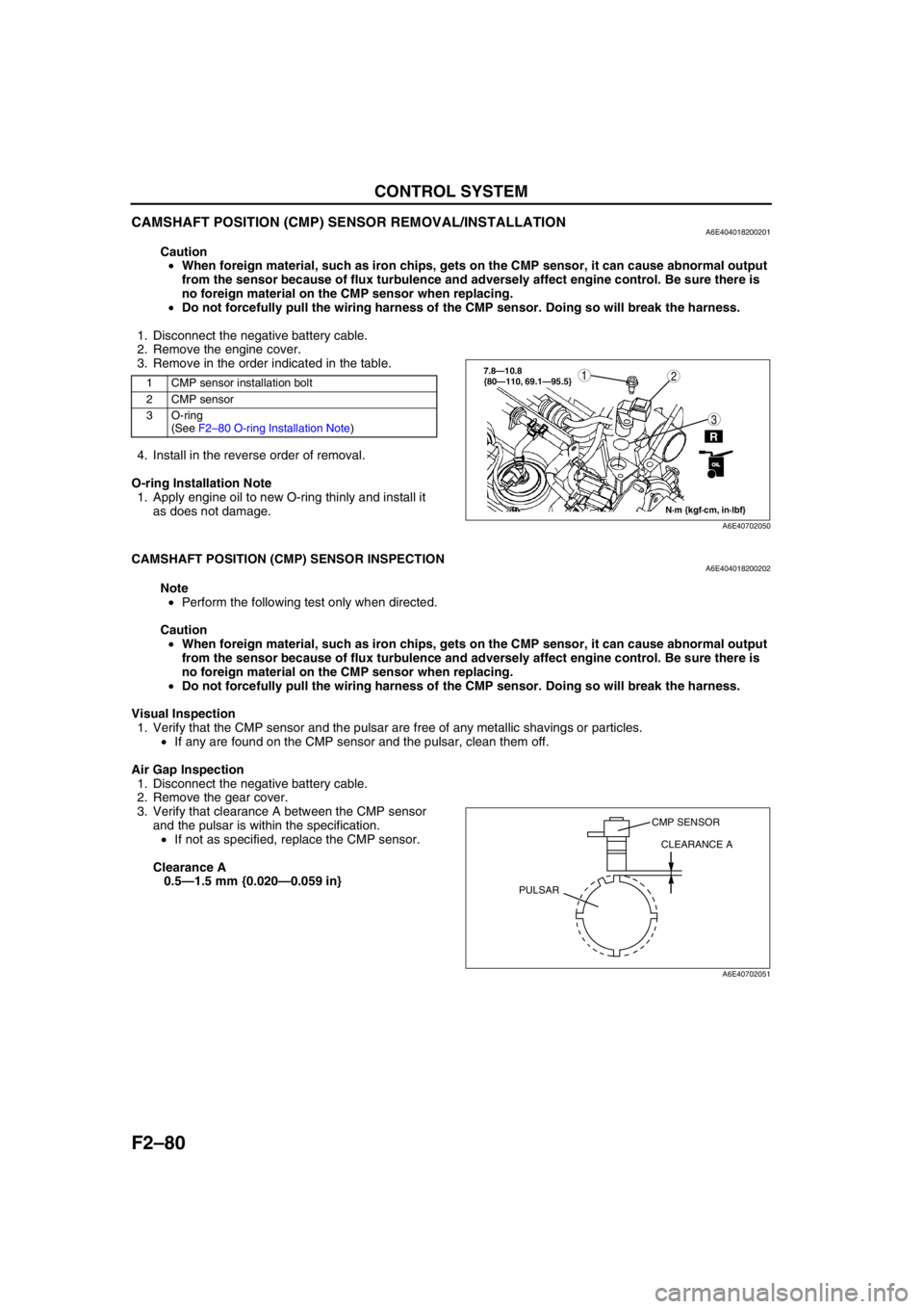
F2–80
CONTROL SYSTEM
CAMSHAFT POSITION (CMP) SENSOR REMOVAL/INSTALLATIONA6E404018200201
Caution
•When foreign material, such as iron chips, gets on the CMP sensor, it can cause abnormal output
from the sensor because of flux turbulence and adversely affect engine control. Be sure there is
no foreign material on the CMP sensor when replacing.
•Do not forcefully pull the wiring harness of the CMP sensor. Doing so will break the harness.
1. Disconnect the negative battery cable.
2. Remove the engine cover.
3. Remove in the order indicated in the table.
4. Install in the reverse order of removal.
O-ring Installation Note
1. Apply engine oil to new O-ring thinly and install it
as does not damage.
End Of Sie
CAMSHAFT POSITION (CMP) SENSOR INSPECTIONA6E404018200202
Note
•Perform the following test only when directed.
Caution
•When foreign material, such as iron chips, gets on the CMP sensor, it can cause abnormal output
from the sensor because of flux turbulence and adversely affect engine control. Be sure there is
no foreign material on the CMP sensor when replacing.
•Do not forcefully pull the wiring harness of the CMP sensor. Doing so will break the harness.
Visual Inspection
1. Verify that the CMP sensor and the pulsar are free of any metallic shavings or particles.
•If any are found on the CMP sensor and the pulsar, clean them off.
Air Gap Inspection
1. Disconnect the negative battery cable.
2. Remove the gear cover.
3. Verify that clearance A between the CMP sensor
and the pulsar is within the specification.
•If not as specified, replace the CMP sensor.
Clearance A
0.5—1.5 mm {0.020—0.059 in}
1 CMP sensor installation bolt
2 CMP sensor
3 O-ring
(See F2–80 O-ring Installation Note)
N·m {kgf·cm, in·lbf}
3
127.8—10.8
{80—110, 69.1—95.5}
R
OILOIL
A6E40702050
CMP SENSOR
CLEARANCE A
PULSAR
A6E40702051
Page 239 of 909
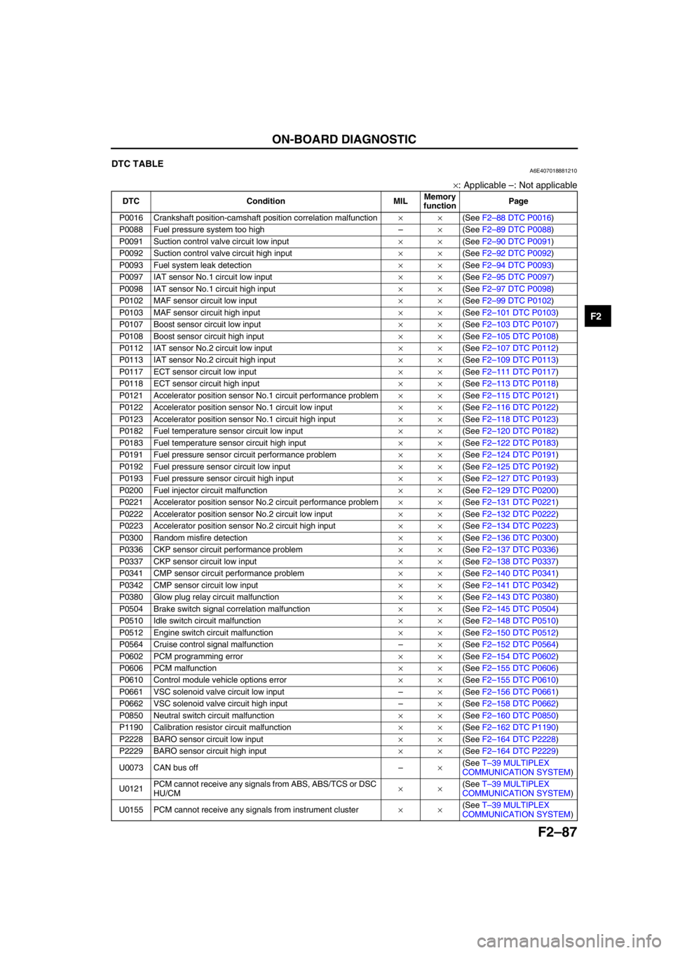
ON-BOARD DIAGNOSTIC
F2–87
F2
End Of SieDTC TABLEA6E407018881210
×: Applicable –: Not applicable
DTC Condition MILMemory
functionPage
P0016 Crankshaft position-camshaft position correlation malfunction××(See F2–88 DTC P0016)
P0088 Fuel pressure system too high–×(See F2–89 DTC P0088)
P0091 Suction control valve circuit low input××(See F2–90 DTC P0091)
P0092 Suction control valve circuit high input××(See F2–92 DTC P0092)
P0093 Fuel system leak detection××(See F2–94 DTC P0093)
P0097 IAT sensor No.1 circuit low input××(See F2–95 DTC P0097)
P0098 IAT sensor No.1 circuit high input××(See F2–97 DTC P0098)
P0102 MAF sensor circuit low input××(See F2–99 DTC P0102)
P0103 MAF sensor circuit high input××(See F2–101 DTC P0103)
P0107 Boost sensor circuit low input××(See F2–103 DTC P0107)
P0108 Boost sensor circuit high input××(See F2–105 DTC P0108)
P0112 IAT sensor No.2 circuit low input××(See F2–107 DTC P0112)
P0113 IAT sensor No.2 circuit high input××(See F2–109 DTC P0113)
P0117 ECT sensor circuit low input××(See F2–111 DTC P0117)
P0118 ECT sensor circuit high input××(See F2–113 DTC P0118)
P0121 Accelerator position sensor No.1 circuit performance problem××(See F2–115 DTC P0121)
P0122 Accelerator position sensor No.1 circuit low input××(See F2–116 DTC P0122)
P0123 Accelerator position sensor No.1 circuit high input××(See F2–118 DTC P0123)
P0182 Fuel temperature sensor circuit low input××(See F2–120 DTC P0182)
P0183 Fuel temperature sensor circuit high input××(See F2–122 DTC P0183)
P0191 Fuel pressure sensor circuit performance problem××(See F2–124 DTC P0191)
P0192 Fuel pressure sensor circuit low input××(See F2–125 DTC P0192)
P0193 Fuel pressure sensor circuit high input××(See F2–127 DTC P0193)
P0200 Fuel injector circuit malfunction××(See F2–129 DTC P0200)
P0221 Accelerator position sensor No.2 circuit performance problem××(See F2–131 DTC P0221)
P0222 Accelerator position sensor No.2 circuit low input××(See F2–132 DTC P0222)
P0223 Accelerator position sensor No.2 circuit high input××(See F2–134 DTC P0223)
P0300 Random misfire detection××(See F2–136 DTC P0300)
P0336 CKP sensor circuit performance problem××(See F2–137 DTC P0336)
P0337 CKP sensor circuit low input××(See F2–138 DTC P0337)
P0341 CMP sensor circuit performance problem××(See F2–140 DTC P0341)
P0342 CMP sensor circuit low input××(See F2–141 DTC P0342)
P0380 Glow plug relay circuit malfunction××(See F2–143 DTC P0380)
P0504 Brake switch signal correlation malfunction××(See F2–145 DTC P0504)
P0510 Idle switch circuit malfunction××(See F2–148 DTC P0510)
P0512 Engine switch circuit malfunction××(See F2–150 DTC P0512)
P0564 Cruise control signal malfunction–×(See F2–152 DTC P0564)
P0602 PCM programming error××(See F2–154 DTC P0602)
P0606 PCM malfunction××(See F2–155 DTC P0606)
P0610 Control module vehicle options error××(See F2–155 DTC P0610)
P0661 VSC solenoid valve circuit low input–×(See F2–156 DTC P0661)
P0662 VSC solenoid valve circuit high input–×(See F2–158 DTC P0662)
P0850 Neutral switch circuit malfunction××(See F2–160 DTC P0850)
P1190 Calibration resistor circuit malfunction××(See F2–162 DTC P1190)
P2228 BARO sensor circuit low input××(See F2–164 DTC P2228)
P2229 BARO sensor circuit high input××(See F2–164 DTC P2229)
U0073 CAN bus off–×(See T–39 MULTIPLEX
COMMUNICATION SYSTEM)
U0121PCM cannot receive any signals from ABS, ABS/TCS or DSC
HU/CM××(See T–39 MULTIPLEX
COMMUNICATION SYSTEM)
U0155 PCM cannot receive any signals from instrument cluster××(See T–39 MULTIPLEX
COMMUNICATION SYSTEM)
Page 240 of 909
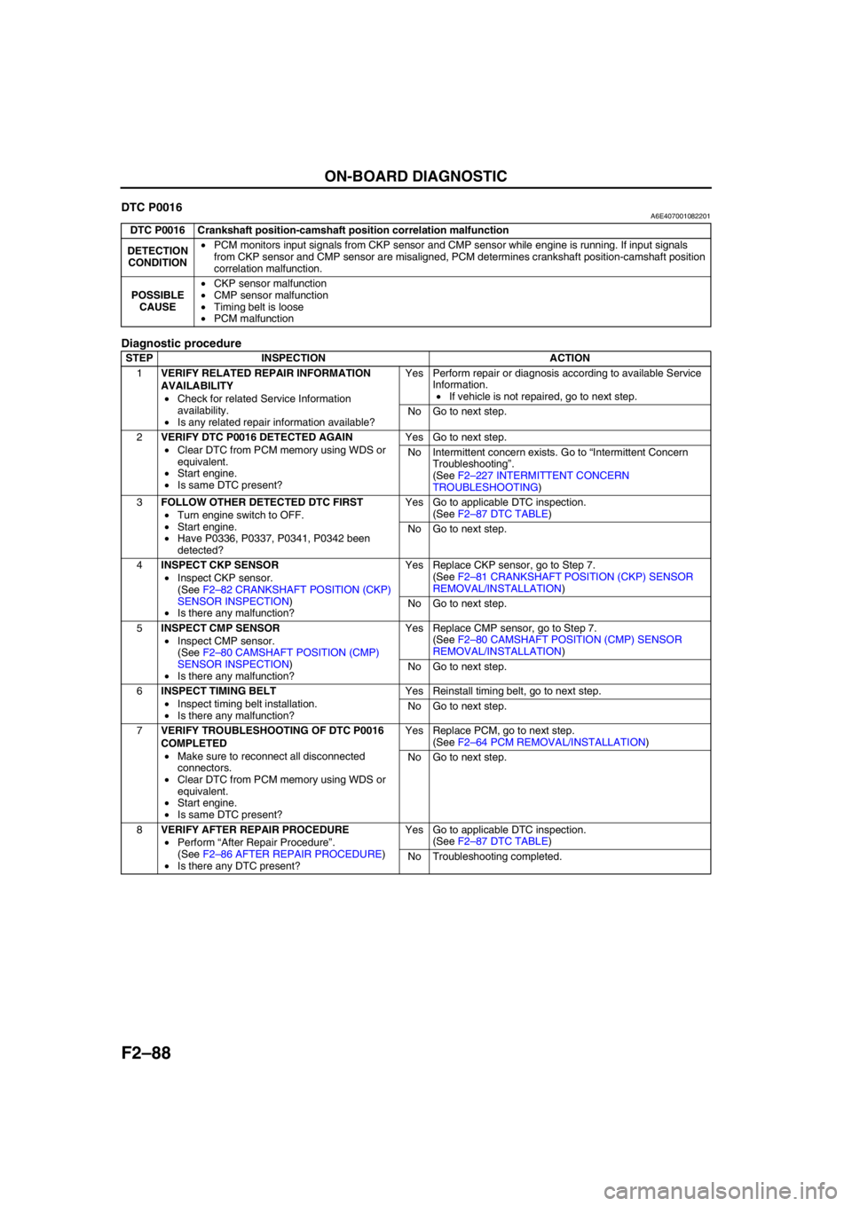
F2–88
ON-BOARD DIAGNOSTIC
End Of SieDTC P0016A6E407001082201
Diagnostic procedure
End Of Sie
DTC P0016 Crankshaft position-camshaft position correlation malfunction
DETECTION
CONDITION•PCM monitors input signals from CKP sensor and CMP sensor while engine is running. If input signals
from CKP sensor and CMP sensor are misaligned, PCM determines crankshaft position-camshaft position
correlation malfunction.
POSSIBLE
CAUSE•CKP sensor malfunction
•CMP sensor malfunction
•Timing belt is loose
•PCM malfunction
STEP INSPECTION ACTION
1VERIFY RELATED REPAIR INFORMATION
AVAILABILITY
•Check for related Service Information
availability.
•Is any related repair information available?Yes Perform repair or diagnosis according to available Service
Information.
•If vehicle is not repaired, go to next step.
No Go to next step.
2VERIFY DTC P0016 DETECTED AGAIN
•Clear DTC from PCM memory using WDS or
equivalent.
•Start engine.
•Is same DTC present?Yes Go to next step.
No Intermittent concern exists. Go to “Intermittent Concern
Troubleshooting”.
(See F2–227 INTERMITTENT CONCERN
TROUBLESHOOTING)
3FOLLOW OTHER DETECTED DTC FIRST
•Turn engine switch to OFF.
•Start engine.
•Have P0336, P0337, P0341, P0342 been
detected?Yes Go to applicable DTC inspection.
(See F2–87 DTC TABLE)
No Go to next step.
4INSPECT CKP SENSOR
•Inspect CKP sensor.
(See F2–82 CRANKSHAFT POSITION (CKP)
SENSOR INSPECTION)
•Is there any malfunction?Yes Replace CKP sensor, go to Step 7.
(See F2–81 CRANKSHAFT POSITION (CKP) SENSOR
REMOVAL/INSTALLATION)
No Go to next step.
5INSPECT CMP SENSOR
•Inspect CMP sensor.
(See F2–80 CAMSHAFT POSITION (CMP)
SENSOR INSPECTION)
•Is there any malfunction?Yes Replace CMP sensor, go to Step 7.
(See F2–80 CAMSHAFT POSITION (CMP) SENSOR
REMOVAL/INSTALLATION)
No Go to next step.
6INSPECT TIMING BELT
•Inspect timing belt installation.
•Is there any malfunction?Yes Reinstall timing belt, go to next step.
No Go to next step.
7VERIFY TROUBLESHOOTING OF DTC P0016
COMPLETED
•Make sure to reconnect all disconnected
connectors.
•Clear DTC from PCM memory using WDS or
equivalent.
•Start engine.
•Is same DTC present?Yes Replace PCM, go to next step.
(See F2–64 PCM REMOVAL/INSTALLATION)
No Go to next step.
8VERIFY AFTER REPAIR PROCEDURE
•Perform “After Repair Procedure”.
(See F2–86 AFTER REPAIR PROCEDURE)
•Is there any DTC present?Yes Go to applicable DTC inspection.
(See F2–87 DTC TABLE)
No Troubleshooting completed.
Page 288 of 909
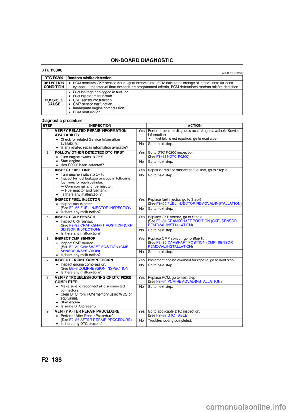
F2–136
ON-BOARD DIAGNOSTIC
DTC P0300A6E407001082228
Diagnostic procedure
End Of Sie
DTC P0300 Random misfire detection
DETECTION
CONDITION•PCM monitors CKP sensor input signal interval time. PCM calculates change of interval time for each
cylinder. If the interval time exceeds preprogrammed criteria, PCM determines random misfire detection.
POSSIBLE
CAUSE•Fuel leakage or clogged in fuel line
•Fuel injector malfunction
•CKP sensor malfunction
•CMP sensor malfunction
•Inadequate engine compression
•PCM malfunction
STEP INSPECTION ACTION
1VERIFY RELATED REPAIR INFORMATION
AVAILABILITY
•Check for related Service Information
availability.
•Is any related repair information available?Yes Perform repair or diagnosis according to available Service
Information.
•If vehicle is not repaired, go to next step.
No Go to next step.
2FOLLOW OTHER DETECTED DTC FIRST
•Turn engine switch to OFF.
•Start engine.
•Has P0200 been detected?Yes Go to DTC P0200 inspection.
(See F2–129 DTC P0200)
No Go to next step.
3INSPECT FUEL LINE
•Turn engine switch to OFF.
•Inspect for fuel leakage or clogs in following
fuel lines for each cylinder:
—Common rail and fuel injector.
—Fuel injector and fuel tank.
• Is there any malfunction?Yes Repair or replace suspected fuel line, go to Step 8.
No Go to next step.
4INSPECT FUEL INJECTOR
•Inspect fuel injector.
(See F2–56 FUEL INJECTOR INSPECTION)
•Is there any malfunction?Yes Replace fuel injector, go to Step 8.
(See F2–55 FUEL INJECTOR REMOVAL/INSTALLATION)
No Go to next step.
5INSPECT CKP SENSOR
•Inspect CKP sensor.
(See F2–82 CRANKSHAFT POSITION (CKP)
SENSOR INSPECTION)
•Is there any malfunction?Yes Replace CKP sensor, go to Step 8.
(See F2–81 CRANKSHAFT POSITION (CKP) SENSOR
REMOVAL/INSTALLATION)
No Go to next step.
6INSPECT CMP SENSOR
•Inspect CMP sensor.
(See F2–80 CAMSHAFT POSITION (CMP)
SENSOR INSPECTION)
•Is there any malfunction?Yes Replace CMP sensor, go to Step 8.
(See F2–80 CAMSHAFT POSITION (CMP) SENSOR
REMOVAL/INSTALLATION)
No Go to next step.
7INSPECT ENGINE COMPRESSION
•Inspect engine compression.
(See B2–8 COMPRESSION INSPECTION)
•Is there any malfunction?Yes Implement engine overhaul for repairs, go to next step.
No Go to next step.
8VERIFY TROUBLESHOOTING OF DTC P0300
COMPLETED
•Make sure to reconnect all disconnected
connectors.
•Clear DTC from PCM memory using WDS or
equivalent.
•Start engine.
•Is same DTC present?Yes Replace PCM, go to next step.
(See F2–64 PCM REMOVAL/INSTALLATION)
No Go to next step.
9VERIFY AFTER REPAIR PROCEDURE
•Perform “After Repair Procedure”.
(See F2–86 AFTER REPAIR PROCEDURE)
•Is there any DTC present?Yes Go to applicable DTC inspection.
(See F2–87 DTC TABLE)
No Troubleshooting completed.