headlights MAZDA 6 2002 Workshop Manual Suplement
[x] Cancel search | Manufacturer: MAZDA, Model Year: 2002, Model line: 6, Model: MAZDA 6 2002Pages: 909, PDF Size: 17.16 MB
Page 140 of 909

F1–52
ON-BOARD DIAGNOSTIC
End Of Sie
DTC (4WD)A6E397018881204•Detection logics and conditions are as shown below.
Controller Area Network (CAN)
PCM cannot receive any signals from TCM (U0101)
•PCM cannot receive any signals from TCM.
End Of Sie
OBD DRIVE MODEA6E397018881205•Performing the Drive Mode inspects the OBD system for proper operation. The Drive Mode must be performed
to ensure that no additional DTCs are present.
•During Drive Mode, the following systems are inspected:
—Oxygen sensor (HO2S)
—Oxygen sensor heater
—Catalytic converter (TWC)
Caution
•While performing the Drive Mode, always operate the vehicle in a safe and lawful manner.
•When the WDS or equivalent is used to observe monitor system condition while driving, be sure to
have another technician with you, or record the data in the WDS or equivalent using the PID/DATA
MONITOR AND RECORD function and inspect later.
Note
•Vehicle speed and engine speed detected by the PCM may differ from that indicated by the speedometer
and tachometer. Use the WDS or equivalent to monitor vehicle speed.
•If the OBD system inspection is not completed during the Drive Mode, the following causes are
considered:
1. The OBD system detects the malfunction.
2. The Drive Mode procedure is not completed correctly.
•Disconnecting the battery will reset the memory. Do not disconnect the battery during and after Drive
Mode.
PCM Adaptive Memory Procedure Drive Mode
Note
•The PCM adaptive memory condition can be confirmed with RFCFLAG PID.
•If RFCFLAG PID is “Learnt”, PCM Adaptive Memory Procedure Drive Mode is not necessary, because
PCM already has adaptive memory.
•If RFCFLAG PID is “Not Learnt”, PCM Adaptive Memory Procedure Drive should be performed before
HO2S Heater, HO2S, and TWC Repair Verification Drive Mode.
1. Start the engine and warm it up completely.
2. Verify all accessory loads (A/C, headlights, blower fan, rear window defroster) are off.
U0101 PCM cannot receive any signals from TCM ON 1 Other×
U0121PCM cannot receive any signals from ABS, ABS/TCS
or DSC HU/CMON 1 Other×
U0155PCM cannot receive any signals from instrument
clusterON 1 Other× DTC No. Condition MIL DC Monitor itemMemory
function
Page 141 of 909

ON-BOARD DIAGNOSTIC
F1–53
F1
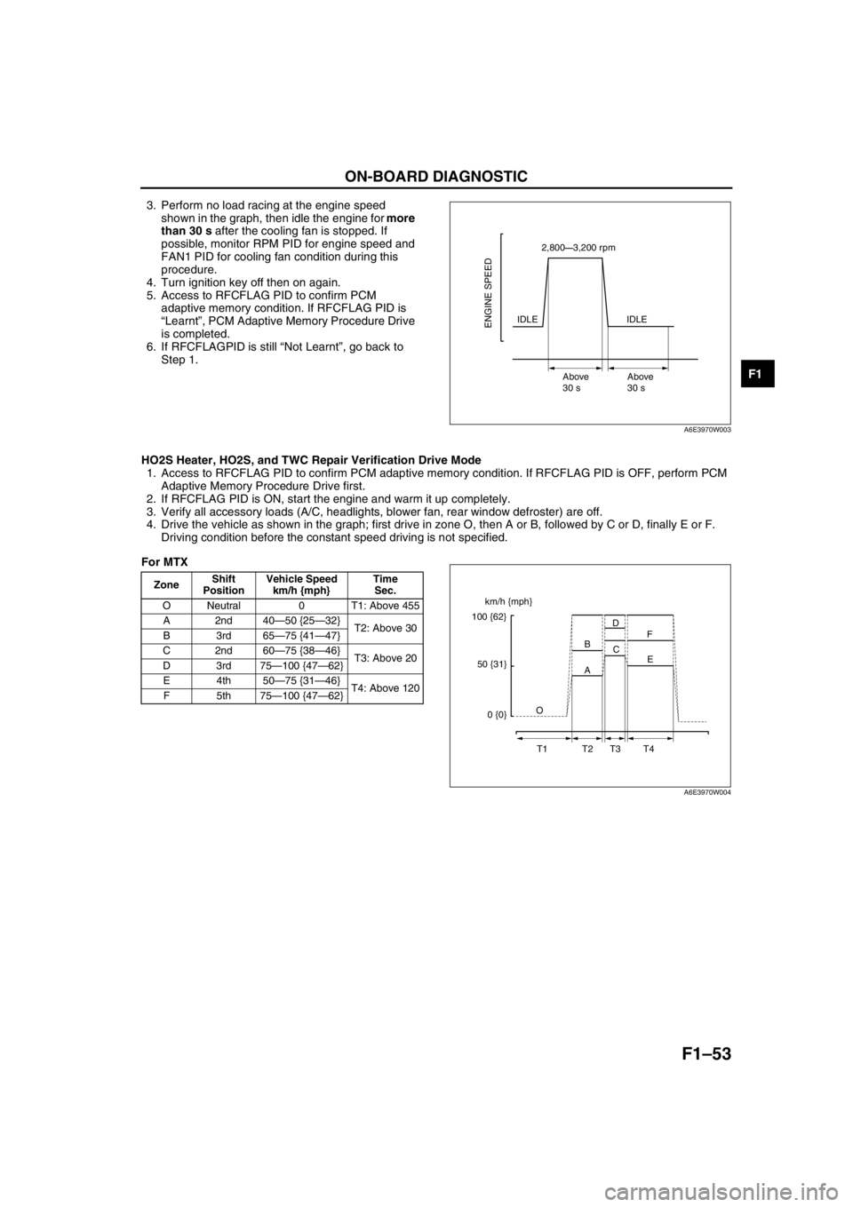
3. Perform no load racing at the engine speed
shown in the graph, then idle the engine for more
than 30 s after the cooling fan is stopped. If
possible, monitor RPM PID for engine speed and
FAN1 PID for cooling fan condition during this
procedure.
4. Turn ignition key off then on again.
5. Access to RFCFLAG PID to confirm PCM
adaptive memory condition. If RFCFLAG PID is
“Learnt”, PCM Adaptive Memory Procedure Drive
is completed.
6. If RFCFLAGPID is still “Not Learnt”, go back to
Step 1.
HO2S Heater, HO2S, and TWC Repair Verification Drive Mode
1. Access to RFCFLAG PID to confirm PCM adaptive memory condition. If RFCFLAG PID is OFF, perform PCM
Adaptive Memory Procedure Drive first.
2. If RFCFLAG PID is ON, start the engine and warm it up completely.
3. Verify all accessory loads (A/C, headlights, blower fan, rear window defroster) are off.
4. Drive the vehicle as shown in the graph; first drive in zone O, then A or B, followed by C or D, finally E or F.
Driving condition before the constant speed driving is not specified.
For MTX
2,800—3,200 rpm
IDLE
Above
30 sAbove
30 s
ENGINE SPEEDIDLE
A6E3970W003
ZoneShift
PositionVehicle Speed
km/h {mph}Time
Sec.
O Neutral 0 T1: Above 455
A2nd40—50 {25—32}
T2: Above 30
B3rd65—75 {41—47}
C2nd60—75 {38—46}
T3: Above 20
D3rd75—100 {47—62}
E4th50—75 {31—46}
T4: Above 120
F5th75—100 {47—62}
km/h {mph}
100 {62}
50 {31}
0 {0}O
T1 T2 T3 T4A BD
C
E F
A6E3970W004
Page 391 of 909

G–8
CHARGING SYSTEM
Generator
Voltage
1. Verify that the battery is fully charged.
•Charge if necessary. (See G–6 BATTERY RECHARGING.)
2. Inspect the drive belt deflection/tension.
(See B2–4 DRIVE BELT INSPECTION.)
•Replace if necessary. (See B2–4 DRIVE BELT REPLACEMENT.)
3. Turn off all electrical loads.
4. Turn the engine switch to start the engine and verify that the generator rotates smoothly without any noise
while the engine is running.
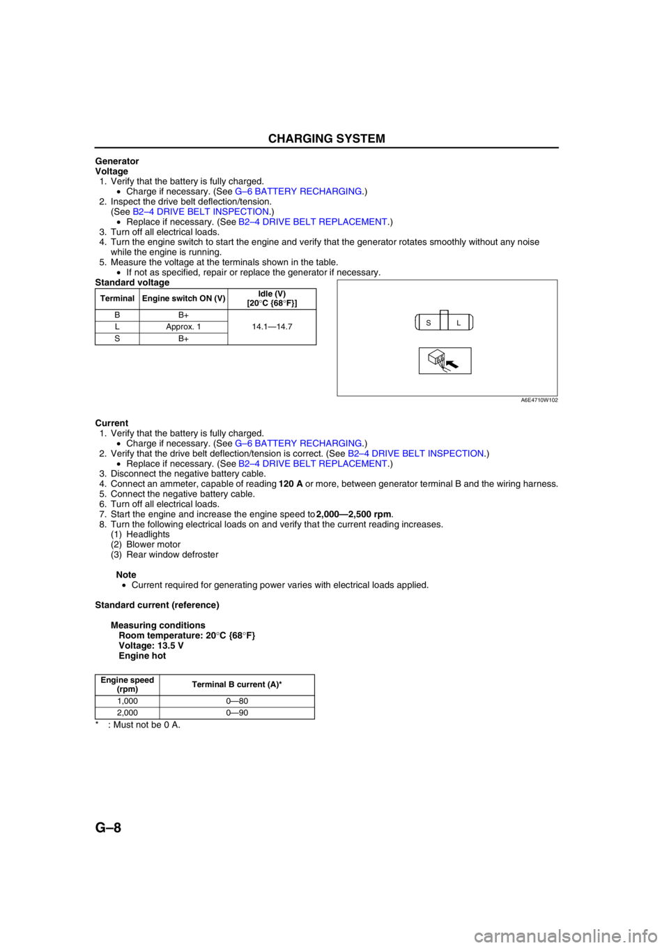
5. Measure the voltage at the terminals shown in the table.
•If not as specified, repair or replace the generator if necessary.
Standard voltage
Current
1. Verify that the battery is fully charged.
•Charge if necessary. (See G–6 BATTERY RECHARGING.)
2. Verify that the drive belt deflection/tension is correct. (See B2–4 DRIVE BELT INSPECTION.)
•Replace if necessary. (See B2–4 DRIVE BELT REPLACEMENT.)
3. Disconnect the negative battery cable.
4. Connect an ammeter, capable of reading 120 A or more, between generator terminal B and the wiring harness.
5. Connect the negative battery cable.
6. Turn off all electrical loads.
7. Start the engine and increase the engine speed to 2,000—2,500 rpm.
8. Turn the following electrical loads on and verify that the current reading increases.
(1) Headlights
(2) Blower motor
(3) Rear window defroster
Note
•Current required for generating power varies with electrical loads applied.
Standard current (reference)
Measuring conditions
Room temperature: 20°C {68°F}
Voltage: 13.5 V
Engine hot
* : Must not be 0 A.
End Of Sie
Terminal Engine switch ON (V)Idle (V)
[20°C {68°F}]
BB+
14.1—14.7 LApprox. 1
SB+
SL
A6E4710W102
Engine speed
(rpm)Terminal B current (A)*
1,000 0—80
2,000 0—90