brake rotor MAZDA MIATA 1991 Factory User Guide
[x] Cancel search | Manufacturer: MAZDA, Model Year: 1991, Model line: MIATA, Model: MAZDA MIATA 1991Pages: 392, PDF Size: 29.45 MB
Page 225 of 392
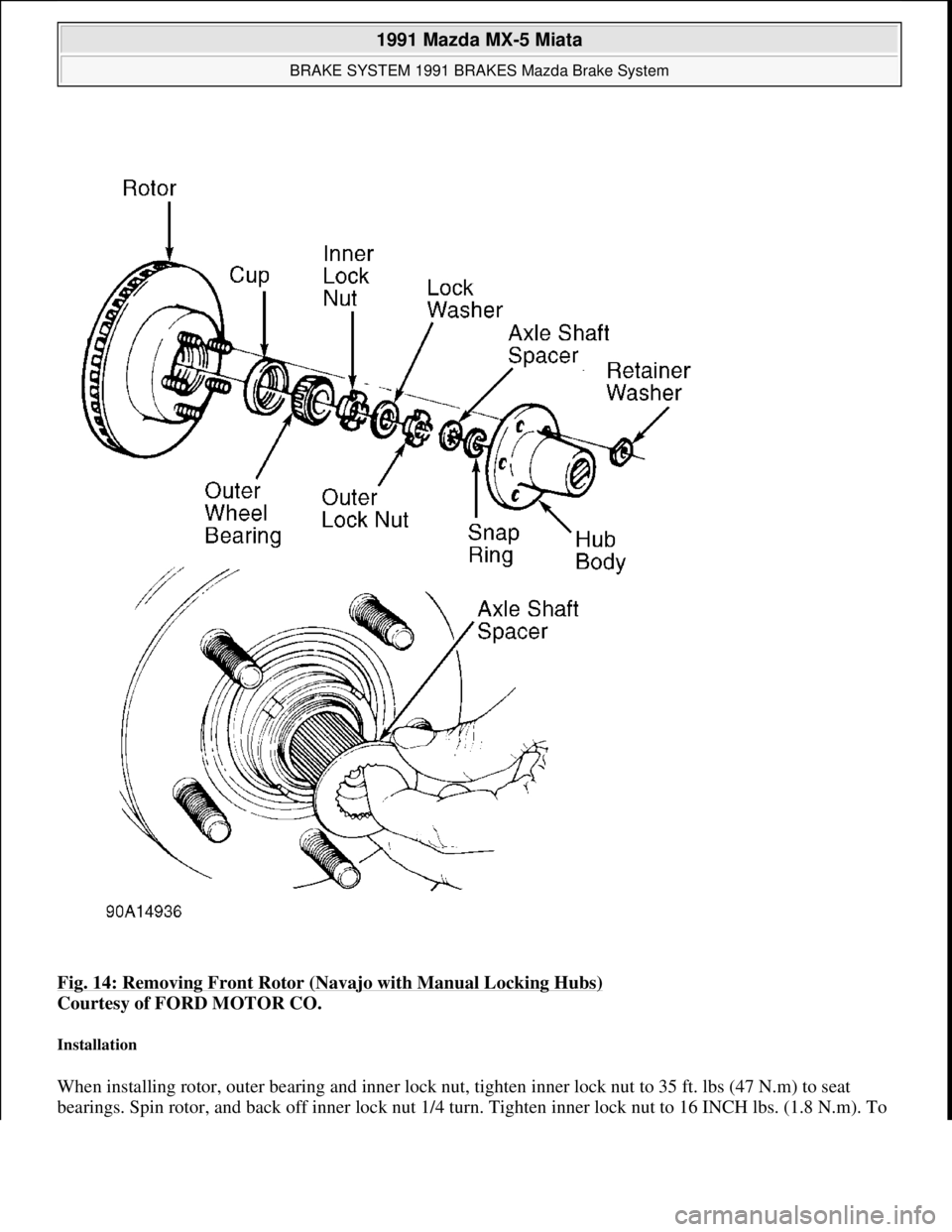
Fig. 14: Removing Front Rotor (Navajo with Manual Locking Hubs)
Courtesy of FORD MOTOR CO.
Installation
When installing rotor, outer bearing and inner lock nut, tighten inner lock nut to 35 ft. lbs (47 N.m) to seat
bearings. Spin rotor, and back off inner lock nut 1/4 turn. Tighten inner lock nut to 16 INCH lbs. (1.8 N.m). To
1991 Mazda MX-5 Miata
BRAKE SYSTEM 1991 BRAKES Mazda Brake System
Microsoft
Sunday, July 05, 2009 2:18:08 PMPage 22 © 2005 Mitchell Repair Information Company, LLC.
Page 226 of 392

install remaining components, reverse removal procedure. See Fig. 14. After assembly is complete, wheel to
spindle end play should be .001-.003" (.02-.08 mm).
Removal & Installation (929)
1. Raise and support front of vehicle. Remove wheel. Remove caliper with brake hose connected. Support
caliper with rope. Remove hub cap, wheel bearing lock nut and washer. Remove hub and rotor assembly.
2. Machine rotor if lateral runout exceeds specification. Replace rotor if measured thickness is less than
specified minimum thickness. See DISC BRAKE SPECIFICATIONS
at end of article.
3. To install, reverse removal procedure. Replace wheel bearing lock nut, and tighten to 72-130 ft. lbs. (98-
177 N.m). Check hub end play. If end play exceeds .002" (.05 mm), replace bearing. If end play is within
specification, stake lock nut at groove in axle shaft.
REAR DISC BRAKE PADS
Removal & Installation (Miata, Protege & 323)
1. Raise and support rear of vehicle. Remove wheel. Remove manual adjustment gear concealment plug
from caliper. See Fig. 15
. Insert an appropriate size Allen wrench through hole and turn manual
ad
justment gear counterclockwise to retract caliper piston.
1991 Mazda MX-5 Miata
BRAKE SYSTEM 1991 BRAKES Mazda Brake System
Microsoft
Sunday, July 05, 2009 2:18:08 PMPage 23 © 2005 Mitchell Repair Information Company, LLC.
Page 228 of 392
2. To install, turn caliper piston clockwise using Disc Brake Piston Wrench (49-FA18-602) to retract caliper
piston. Ensure groove in piston aligns with alignment pin on back of inner pad. To install remaining
components, reverse removal procedure.
Removal & Installation (929)
Raise and support rear of vehicle. Remove wheel. Remove lower guide bolt from caliper. Rotate caliper upward
and secure with rope. Remove pads and shims. Replace pad if lining thickness is less than .08" (2.0 mm). To
install, reverse removal procedure.
REAR BRAKE CALIPER
Removal & Installation
1. Raise and support rear of vehicle. On all models except 929, release parking brake and disconnect parking
brake cable from caliper. On all models, disconnect brake hose from caliper.
2. On Miata, Protege and 323, remove manual adjustment gear concealment plug from caliper. See Fig. 15
.
Insert an appropriate size Allen wrench through hole and turn manual adjustment gear counterclockwise
to retract caliper piston.
3. On all models, remove lower guide bolt from caliper. Rotate caliper upward. Pull caliper toward center of
vehicle to slide it off of caliper mount. To install, reverse removal procedure. Bleed hydraulic system.
REAR BRAKE ROTOR
Removal & Installation (Miata, Protege, RX7, 323 & 929)
Remove rear brake caliper. Remove rotor-to-hub screws. Remove rotor. Machine rotor if lateral runout exceeds
specification. Replace rotor if measured thickness is less than specified minimum thickness. See DISC BRAKE
SPECIFICATIONS at end of article. To install, reverse removal procedure.
Removal & Installation (MX-6 & 626)
1. Remove rear caliper, and wire aside. Remove grease cap. Remove lock nut. Remove rotor. Machine rotor
if lateral runout exceeds specification. Replace rotor if measured thickness is less than specified minimum
thickness. See DISC BRAKE SPECIFICATIONS
at end of article.
2. To install, reverse removal procedure. Tighten lock nut to 73-131 ft. lbs. (99-178 N.m). Check end play at
grease cap. If end play exceeds .008" (.20 mm), replace wheel bearings.
REAR BRAKE SHOES
Removal (B2200, B2600i & MPV)
With brake drum removed, remove brake shoe return springs, retaining springs and guide pins. See Fig. 16 or
Fig. 17
. Remove brake shoes. Remove parking brake strut, and disconnect parking brake cable from operating
lever of secondar
y shoe. Minimum lining thickness is .04" (1 mm).
1991 Mazda MX-5 Miata
BRAKE SYSTEM 1991 BRAKES Mazda Brake System
Microsoft
Sunday, July 05, 2009 2:18:08 PMPage 25 © 2005 Mitchell Repair Information Company, LLC.
Page 234 of 392
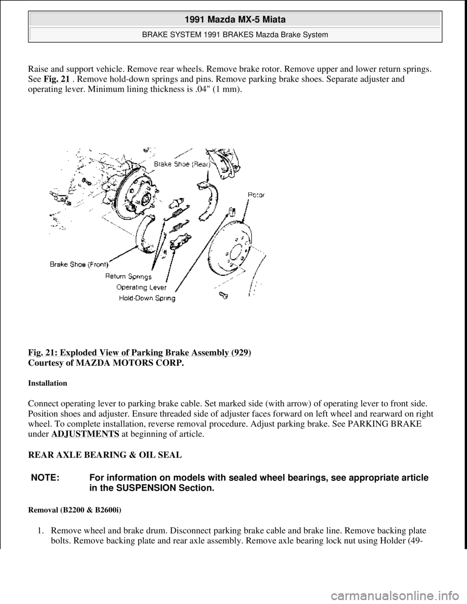
Raise and support vehicle. Remove rear wheels. Remove brake rotor. Remove upper and lower return springs.
See Fig. 21
. Remove hold-down springs and pins. Remove parking brake shoes. Separate adjuster and
operating lever. Minimum lining thickness is .04" (1 mm).
Fig. 21: Exploded View of Parking Brake Assembly (929)
Courtesy of MAZDA MOTORS CORP.
Installation
Connect operating lever to parking brake cable. Set marked side (with arrow) of operating lever to front side.
Position shoes and adjuster. Ensure threaded side of adjuster faces forward on left wheel and rearward on right
wheel. To complete installation, reverse removal procedure. Adjust parking brake. See PARKING BRAKE
under ADJUSTMENTS
at beginning of article.
REAR AXLE BEARING & OIL SEAL
Removal (B2200 & B2600i)
1. Remove wheel and brake drum. Disconnect parking brake cable and brake line. Remove backing plate
bolts. Remove backing plate and rear axle assembly. Remove axle bearing lock nut using Holder (49-
NOTE: For information on models with sealed wheel bearings, see appropriate article
in the SUSPENSION Section.
1991 Mazda MX-5 Miata
BRAKE SYSTEM 1991 BRAKES Mazda Brake System
Microsoft
Sunday, July 05, 2009 2:18:08 PMPage 31 © 2005 Mitchell Repair Information Company, LLC.
Page 242 of 392
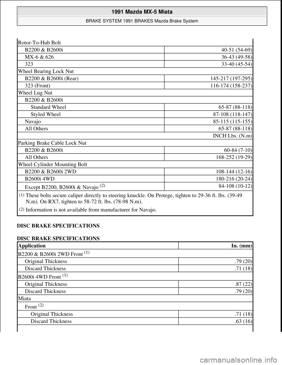
DISC BRAKE SPECIFICATIONS
DISC BRAKE SPECIFICATIONS
Rotor-To-Hub Bolt
B2200 & B2600i40-51 (54-69)
MX-6 & 62636-43 (49-58)
32333-40 (45-54)
Wheel Bearing Lock Nut
B2200 & B2600i (Rear)145-217 (197-295)
323 (Front)116-174 (158-237)
Wheel Lug Nut
B2200 & B2600i
Standard Wheel65-87 (88-118)
Styled Wheel87-108 (118-147)
Navajo85-115 (115-155)
All Others65-87 (88-118)
INCH Lbs. (N.m)
Parking Brake Cable Lock Nut
B2200 & B2600i60-84 (7-10)
All Others168-252 (19-29)
Wheel Cylinder Mounting Bolt
B2200 & B2600i 2WD108-144 (12-16)
B2600i 4WD180-216 (20-24)
Except B2200, B2600i & Navajo (2) 84-108 (10-12)
(1)These bolts secure caliper directly to steering knuckle. On Protege, tighten to 29-36 ft. lbs. (39-49
N.m). On RX7, tighten to 58-72 ft. lbs. (78-98 N.m).
(2)Information is not available from manufacturer for Navajo.
ApplicationIn. (mm)
B2200 & B2600i 2WD Front (1)
Original Thickness.79 (20)
Discard Thickness.71 (18)
B2600i 4WD Front (1)
Original Thickness.87 (22)
Discard Thickness.79 (20)
Miata
Front (2)
Original Thickness.71 (18)
Discard Thickness.63 (16)
1991 Mazda MX-5 Miata
BRAKE SYSTEM 1991 BRAKES Mazda Brake System
Microsoft
Sunday, July 05, 2009 2:18:09 PMPage 39 © 2005 Mitchell Repair Information Company, LLC.
Page 243 of 392
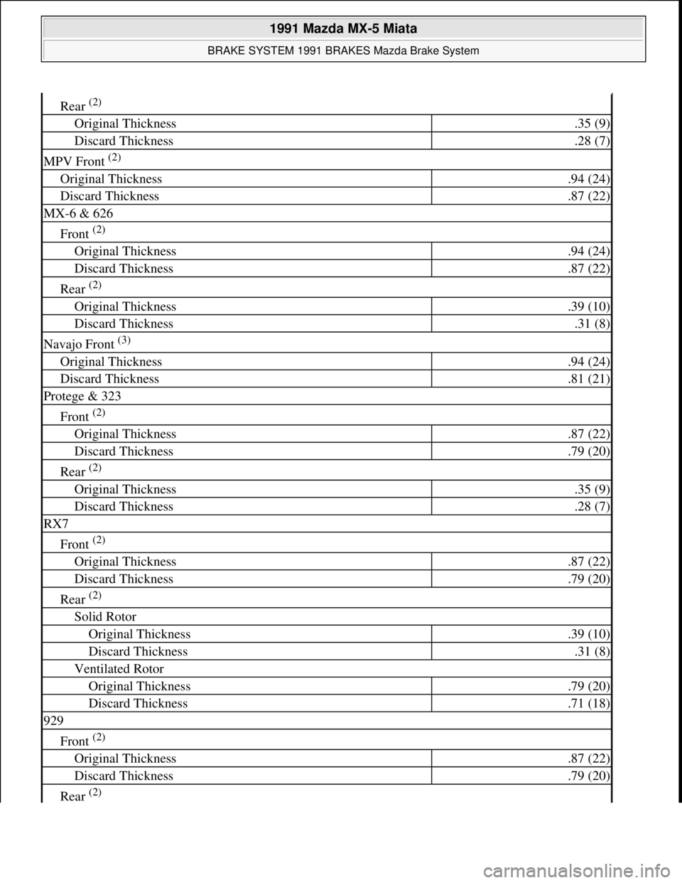
Rear (2)
Original Thickness.35 (9)
Discard Thickness.28 (7)
MPV Front (2)
Original Thickness.94 (24)
Discard Thickness.87 (22)
MX-6 & 626
Front (2)
Original Thickness.94 (24)
Discard Thickness.87 (22)
Rear (2)
Original Thickness.39 (10)
Discard Thickness.31 (8)
Navajo Front (3)
Original Thickness.94 (24)
Discard Thickness.81 (21)
Protege & 323
Front (2)
Original Thickness.87 (22)
Discard Thickness.79 (20)
Rear (2)
Original Thickness.35 (9)
Discard Thickness.28 (7)
RX7
Front (2)
Original Thickness.87 (22)
Discard Thickness.79 (20)
Rear (2)
Solid Rotor
Original Thickness.39 (10)
Discard Thickness.31 (8)
Ventilated Rotor
Original Thickness.79 (20)
Discard Thickness.71 (18)
929
Front (2)
Original Thickness.87 (22)
Discard Thickness.79 (20)
Rear (2)
1991 Mazda MX-5 Miata
BRAKE SYSTEM 1991 BRAKES Mazda Brake System
Microsoft
Sunday, July 05, 2009 2:18:09 PMPage 40 © 2005 Mitchell Repair Information Company, LLC.
Page 299 of 392
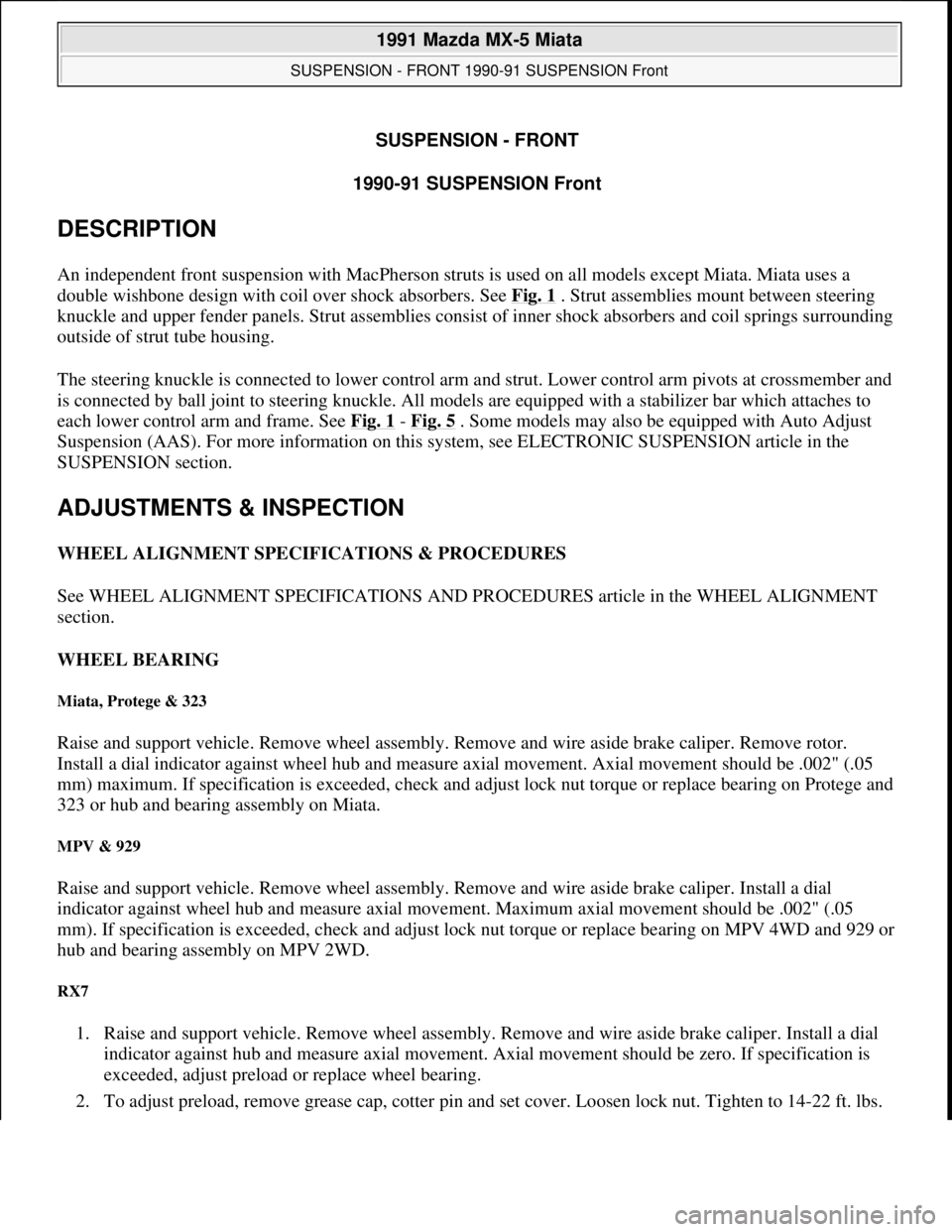
SUSPENSION - FRONT
1990-91 SUSPENSION Front
DESCRIPTION
An independent front suspension with MacPherson struts is used on all models except Miata. Miata uses a
double wishbone design with coil over shock absorbers. See Fig. 1
. Strut assemblies mount between steering
knuckle and upper fender panels. Strut assemblies consist of inner shock absorbers and coil springs surrounding
outside of strut tube housing.
The steering knuckle is connected to lower control arm and strut. Lower control arm pivots at crossmember and
is connected by ball joint to steering knuckle. All models are equipped with a stabilizer bar which attaches to
each lower control arm and frame. See Fig. 1
- Fig. 5 . Some models may also be equipped with Auto Adjust
Suspension (AAS). For more information on this system, see ELECTRONIC SUSPENSION article in the
SUSPENSION section.
ADJUSTMENTS & INSPECTION
WHEEL ALIGNMENT SPECIFICATIONS & PROCEDURES
See WHEEL ALIGNMENT SPECIFICATIONS AND PROCEDURES article in the WHEEL ALIGNMENT
section.
WHEEL BEARING
Miata, Protege & 323
Raise and support vehicle. Remove wheel assembly. Remove and wire aside brake caliper. Remove rotor.
Install a dial indicator against wheel hub and measure axial movement. Axial movement should be .002" (.05
mm) maximum. If specification is exceeded, check and adjust lock nut torque or replace bearing on Protege and
323 or hub and bearing assembly on Miata.
MPV & 929
Raise and support vehicle. Remove wheel assembly. Remove and wire aside brake caliper. Install a dial
indicator against wheel hub and measure axial movement. Maximum axial movement should be .002" (.05
mm). If specification is exceeded, check and adjust lock nut torque or replace bearing on MPV 4WD and 929 or
hub and bearing assembly on MPV 2WD.
RX7
1. Raise and support vehicle. Remove wheel assembly. Remove and wire aside brake caliper. Install a dial
indicator against hub and measure axial movement. Axial movement should be zero. If specification is
exceeded, adjust preload or replace wheel bearing.
2. To ad
just preload, remove grease cap, cotter pin and set cover. Loosen lock nut. Tighten to 14-22 ft. lbs.
1991 Mazda MX-5 Miata
SUSPENSION - FRONT 1990-91 SUSPENSION Front
1991 Mazda MX-5 Miata
SUSPENSION - FRONT 1990-91 SUSPENSION Front
Microsoft
Sunday, July 05, 2009 2:08:53 PMPage 1 © 2005 Mitchell Repair Information Company, LLC.
Microsoft
Sunday, July 05, 2009 2:09:01 PMPage 1 © 2005 Mitchell Repair Information Company, LLC.
Page 304 of 392

Fig. 5: Identifying Front Suspension Components (MX-6 & 626)
Courtesy of MAZDA MOTORS CORP.
REMOVAL & INSTALLATION
WHEEL BEARING
Removal (Miata & MPV 2WD)
Raise and support vehicle. Remove wheel assembly. Remove and wire aside brake caliper. Remove grease cap
and lock nut. Remove brake rotor. Remove hub and bearing assembly.
Removal (MPV 4WD)
NOTE: Refer to Fig. 1 - Fig. 5 during removal and installation.
NOTE: On Miata & MPV 2WD, replace hub and bearing assembly as a unit.
1991 Mazda MX-5 Miata
SUSPENSION - FRONT 1990-91 SUSPENSION Front
Microsoft
Sunday, July 05, 2009 2:08:54 PMPage 6 © 2005 Mitchell Repair Information Company, LLC.
Page 305 of 392
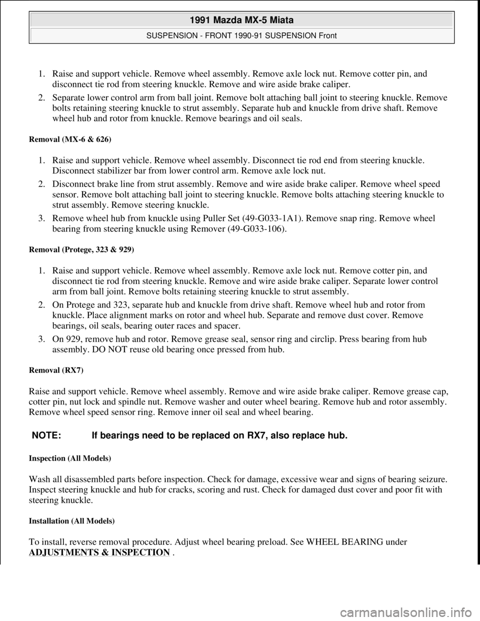
1. Raise and support vehicle. Remove wheel assembly. Remove axle lock nut. Remove cotter pin, and
disconnect tie rod from steering knuckle. Remove and wire aside brake caliper.
2. Separate lower control arm from ball joint. Remove bolt attaching ball joint to steering knuckle. Remove
bolts retaining steering knuckle to strut assembly. Separate hub and knuckle from drive shaft. Remove
wheel hub and rotor from knuckle. Remove bearings and oil seals.
Removal (MX-6 & 626)
1. Raise and support vehicle. Remove wheel assembly. Disconnect tie rod end from steering knuckle.
Disconnect stabilizer bar from lower control arm. Remove axle lock nut.
2. Disconnect brake line from strut assembly. Remove and wire aside brake caliper. Remove wheel speed
sensor. Remove bolt attaching ball joint to steering knuckle. Remove bolts attaching steering knuckle to
strut assembly. Remove steering knuckle.
3. Remove wheel hub from knuckle using Puller Set (49-G033-1A1). Remove snap ring. Remove wheel
bearing from steering knuckle using Remover (49-G033-106).
Removal (Protege, 323 & 929)
1. Raise and support vehicle. Remove wheel assembly. Remove axle lock nut. Remove cotter pin, and
disconnect tie rod from steering knuckle. Remove and wire aside brake caliper. Separate lower control
arm from ball joint. Remove bolts retaining steering knuckle to strut assembly.
2. On Protege and 323, separate hub and knuckle from drive shaft. Remove wheel hub and rotor from
knuckle. Place alignment marks on rotor and wheel hub. Separate and remove dust cover. Remove
bearings, oil seals, bearing outer races and spacer.
3. On 929, remove hub and rotor. Remove grease seal, sensor ring and circlip. Press bearing from hub
assembly. DO NOT reuse old bearing once pressed from hub.
Removal (RX7)
Raise and support vehicle. Remove wheel assembly. Remove and wire aside brake caliper. Remove grease cap,
cotter pin, nut lock and spindle nut. Remove washer and outer wheel bearing. Remove hub and rotor assembly.
Remove wheel speed sensor ring. Remove inner oil seal and wheel bearing.
Inspection (All Models)
Wash all disassembled parts before inspection. Check for damage, excessive wear and signs of bearing seizure.
Inspect steering knuckle and hub for cracks, scoring and rust. Check for damaged dust cover and poor fit with
steering knuckle.
Installation (All Models)
To install, reverse removal procedure. Adjust wheel bearing preload. See WHEEL BEARING under
ADJUSTMENTS & INSPECTION
. NOTE: If bearings need to be replaced on RX7, also replace hub.
1991 Mazda MX-5 Miata
SUSPENSION - FRONT 1990-91 SUSPENSION Front
Microsoft
Sunday, July 05, 2009 2:08:54 PMPage 7 © 2005 Mitchell Repair Information Company, LLC.
Page 352 of 392

SUSPENSION - REAR
1991 SUSPENSION Rear
DESCRIPTION
Rear suspension consists of MacPherson-type struts, crossmember, upper and lower arms and stabilizer bar with
control link. Upper and lower arms attach to crossmember and knuckle. A stabilizer bar with control link is
mounted to lower arm and crossmember. Rear wheel alignment is adjusted by turning adjusting cams on lower
arm.
ADJUSTMENTS & INSPECTION
WHEEL ALIGNMENT SPECIFICATIONS & PROCEDURES
See WHEEL ALIGNMENT SPECIFICATIONS AND PROCEDURES article in the WHEEL ALIGNMENT
section.
WHEEL BEARING
Raise vehicle and support. Remove wheel assembly. Remove caliper assembly and wire aside. Remove brake
rotor. Attach dial indicator to axle hub and measure bearing play. Maximum bearing play is .002" (.05 mm). If
play exceeds specification, check rear axle lock nut torque or replace wheel bearing.
REMOVAL & INSTALLATION
WHEEL BEARING
Removal
1. Raise and support vehicle. Remove wheel assembly. Remove drive axle lock nut. Remove brake caliper
assembly, and wire aside. Remove screws and rotor. Disconnect ABS speed sensor. Remove knuckle
assembly from upper and lower arms.
2. Using a press, Installer (49-G030-727) and Puller (49-F026-103), remove hub from knuckle. Remove
snap ring from knuckle. Using a press, installer and Puller (49-0636-145), remove wheel bearing inner
race from hub. Remove wheel bearing outer race from knuckle using a press and Adapter (49-F027-005).
Inspection
Check wheel hub and knuckle for cracks and damage. Check dust cover for deformation. Check bearing for
excessive wear or seizure.
Installation
Press new wheel bearing into knuckle using Installer (49-F027-007) and Adapter (49-F027-009). Press hub into
knuckle using installer. To install, reverse removal procedure. Tighten drive axle lock nut to specification. Stake
1991 Mazda MX-5 Miata
SUSPENSION - REAR 1991 SUSPENSION Rear
1991 Mazda MX-5 Miata
SUSPENSION - REAR 1991 SUSPENSION Rear
Microsoft
Sunday, July 05, 2009 2:09:35 PMPage 1 © 2005 Mitchell Repair Information Company, LLC.
Microsoft
Sunday, July 05, 2009 2:09:39 PMPage 1 © 2005 Mitchell Repair Information Company, LLC.