horn MAZDA MIATA 1991 Factory Service Manual
[x] Cancel search | Manufacturer: MAZDA, Model Year: 1991, Model line: MIATA, Model: MAZDA MIATA 1991Pages: 392, PDF Size: 29.45 MB
Page 134 of 392
Removal
1. Before proceeding, follow air bag service precautions. See SERVICE PRECAUTIONS. Disable air bag
system. See DISABLING & ACTIVATING AIR BAG SYSTEM.
2. Clockspring connector assembly is located under steering wheel, in steering column. See Fig. 4
or Fig. 5.
Remove air bag module. See AIR BAG MODULE. Remove steering wheel nut and remove steering
wheel with steering wheel puller. Remove column covers. Remove screws. Remove clockspring
connector and combination switch as an assembly.
DIAGNOSTIC MODULE & BACK-UP BATTERY
Removal & Installation
1. Before proceeding, follow air bag service precautions. See SERVICE PRECAUTIONS. Disable air bag
system. See DISABLING & ACTIVATING AIR BAG SYSTEM.
2. Diagnostic module and back-up battery is located under left side of instrument panel. See Fig. 4
or Fig.
5 . Disconnect diagnostic module and back-up battery connectors. Remove nuts. Remove diagnostic
module and back-up battery as an assembly. To install, reverse removal procedure. After diagnostic
module and back-up battery are installed, reactivate air bag system. See DISABLING & ACTIVATING
AIR BAG SYSTEM. Check AIR BAG indicator light to ensure system is functioning properly. See
SYSTEM OPERATION CHECK.
SYSTEM OPERATION CHECK
Turn ignition switch to the ON or START position. AIR BAG warning light in instrument cluster should
illuminate for approximately 6 seconds then go out. This indicates that the air bag system is functioning
properly. If any of the following conditions exists, air bag system is malfunctioning and needs repair.
AIR BAG warning light does not illuminate as described.
AIR BAG warning light stays on for more than 6 seconds.
AIR BAG warning light illuminates while driving.
If air bag system components are replaced for any reason, air bag system must be checked for proper function
after repair. Turn ignition on. AIR BAG warning light should illuminate for approximately 6 seconds then go
out. If AIR BAG warning light does not illuminate as described, air bag system is malfunctioning and needs
repair. If warning light functions as described, check horn operation. If horn does not sound, remove air bag
module and check air bag module and horn switch connections. Always follow service precautions and
deactivate air bag system before performing repairs. See DISABLING & ACTIVATING AIR BAG
SYSTEM .
WIRE REPAIR
DO NOT repair air bag system wiring. If air bag harness connectors are faulty, replace faulty wiring harness.
TORQUE SPECIFICATIONS
1991 Mazda MX-5 Miata
AIR BAG RESTRAINT SYSTEM MAZDA 1990-91 AIR BAGS
Microsoft
Sunday, July 05, 2009 2:11:16 PMPage 9 © 2005 Mitchell Repair Information Company, LLC.
Page 293 of 392
ELECTRICAL COMPONENT LOCATOR
1991 MAZDA ELECTRICAL COMPONENTS
BUZZERS, RELAYS & TIMERS
BUZZERS, RELAYS & TIMERS LOCATION
CIRCUIT PROTECTION DEVICES
CIRCUIT PROTECTION DEVICES LOCATION
CONTROL UNITS
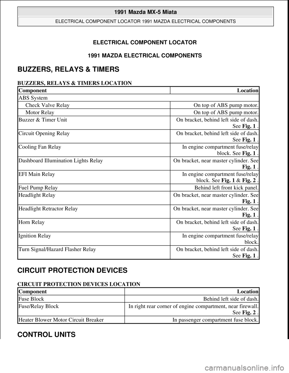
ComponentLocation
ABS System
Check Valve RelayOn top of ABS pump motor.
Motor RelayOn top of ABS pump motor.
Buzzer & Timer UnitOn bracket, behind left side of dash.
See Fig. 1
.
Circuit Opening RelayOn bracket, behind left side of dash.
See Fig. 1
.
Cooling Fan RelayIn engine compartment fuse/relay
block. See Fig. 1
.
Dashboard Illumination Lights RelayOn bracket, near master cylinder. See
Fig. 1
.
EFI Main RelayIn engine compartment fuse/relay
block. See Fig. 1
& Fig. 2 .
Fuel Pump RelayBehind left front kick panel.
Headlight RelayOn bracket, near master cylinder. See
Fig. 1
.
Headlight Retractor RelayOn bracket, near master cylinder. See
Fig. 1
.
Horn RelayOn bracket, behind left side of dash.
See Fig. 1
.
Ignition RelayIn engine compartment fuse/relay
block.
Turn Signal/Hazard Flasher RelayOn bracket, behind left side of dash.
See Fig. 1
.
ComponentLocation
Fuse BlockBehind left side of dash.
Fuse/Relay BlockIn right rear corner of engine compartment, near firewall.
See Fig. 2
.
Heater Blower Motor Circuit BreakerIn passenger compartment fuse block.
1991 Mazda MX-5 Miata
ELECTRICAL COMPONENT LOCATOR 1991 MAZDA ELECTRICAL COMPONENTS
1991 Mazda MX-5 Miata
ELECTRICAL COMPONENT LOCATOR 1991 MAZDA ELECTRICAL COMPONENTS
Microsoft
Sunday, July 05, 2009 2:15:23 PMPage 1 © 2005 Mitchell Repair Information Company, LLC.
Microsoft
Sunday, July 05, 2009 2:15:28 PMPage 1 © 2005 Mitchell Repair Information Company, LLC.
Page 315 of 392
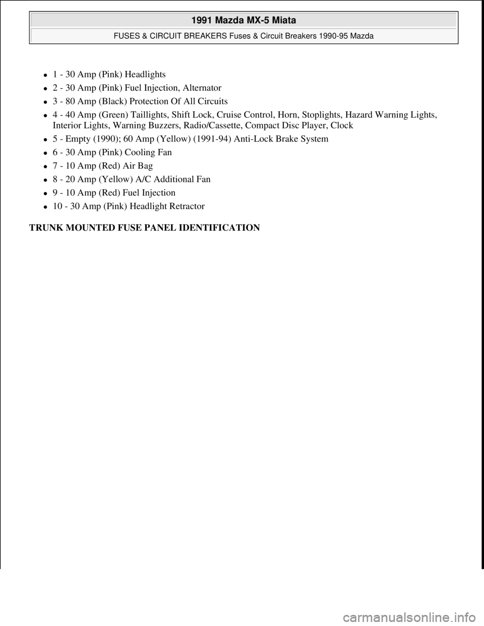
1 - 30 Amp (Pink) Headlights
2 - 30 Amp (Pink) Fuel Injection, Alternator
3 - 80 Amp (Black) Protection Of All Circuits
4 - 40 Amp (Green) Taillights, Shift Lock, Cruise Control, Horn, Stoplights, Hazard Warning Lights,
Interior Lights, Warning Buzzers, Radio/Cassette, Compact Disc Player, Clock
5 - Empty (1990); 60 Amp (Yellow) (1991-94) Anti-Lock Brake System
6 - 30 Amp (Pink) Cooling Fan
7 - 10 Amp (Red) Air Bag
8 - 20 Amp (Yellow) A/C Additional Fan
9 - 10 Amp (Red) Fuel Injection
10 - 30 Amp (Pink) Headlight Retractor
TRUNK MOUNTED FUSE PANEL IDENTIFICATION
1991 Mazda MX-5 Miata
FUSES & CIRCUIT BREAKERS Fuses & Circuit Breakers 1990-95 Mazda
Microsoft
Sunday, July 05, 2009 2:15:54 PMPage 2 © 2005 Mitchell Repair Information Company, LLC.
Page 317 of 392
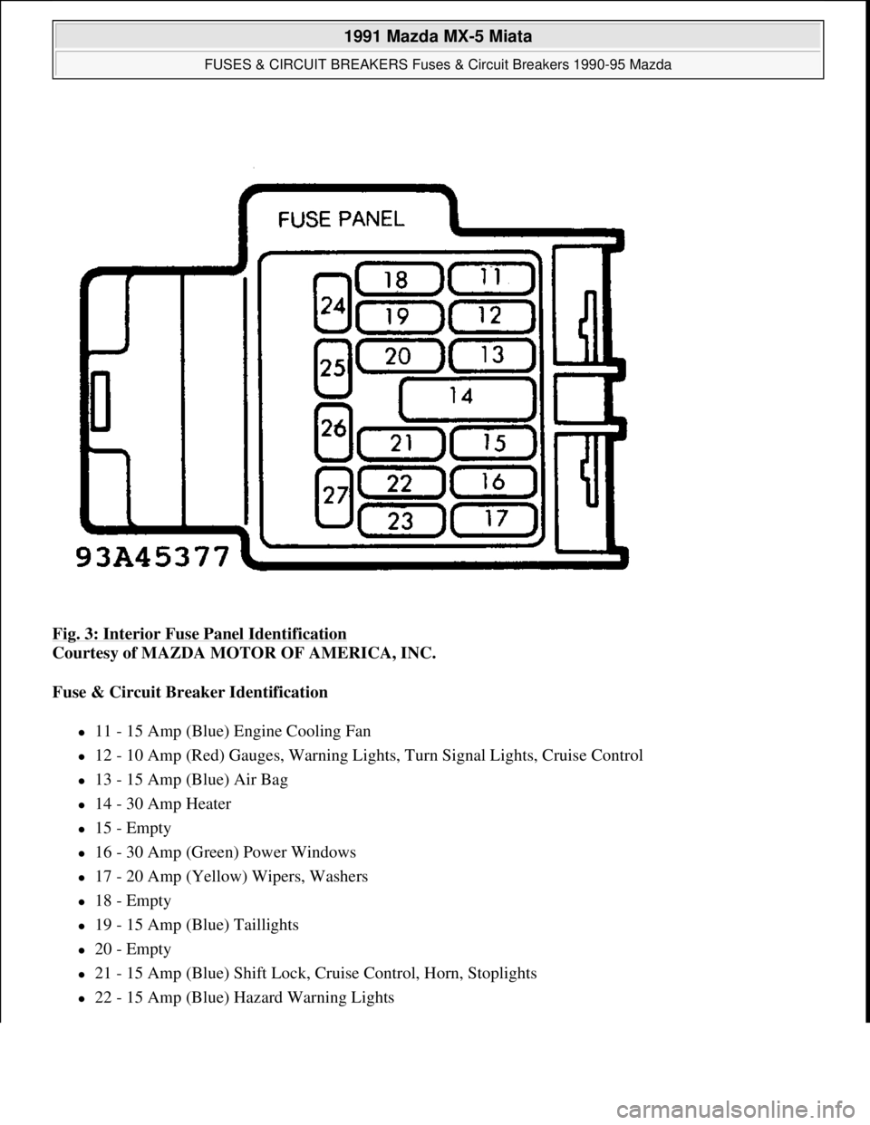
Fig. 3: Interior Fuse Panel Identification
Courtesy of MAZDA MOTOR OF AMERICA, INC.
Fuse & Circuit Breaker Identification
11 - 15 Amp (Blue) Engine Cooling Fan
12 - 10 Amp (Red) Gauges, Warning Lights, Turn Signal Lights, Cruise Control
13 - 15 Amp (Blue) Air Bag
14 - 30 Amp Heater
15 - Empty
16 - 30 Amp (Green) Power Windows
17 - 20 Amp (Yellow) Wipers, Washers
18 - Empty
19 - 15 Amp (Blue) Taillights
20 - Empty
21 - 15 Amp (Blue) Shift Lock, Cruise Control, Horn, Stoplights
22 - 15 Amp (Blue) Hazard Warning Lights
1991 Mazda MX-5 Miata
FUSES & CIRCUIT BREAKERS Fuses & Circuit Breakers 1990-95 Mazda
Microsoft
Sunday, July 05, 2009 2:15:54 PMPage 4 © 2005 Mitchell Repair Information Company, LLC.
Page 318 of 392
23 - Empty
24 - 10 Amp (Red) Interior Lights, Warning Buzzers, Radio/Cassette, Compact Disc Player, Clock
25 - 15 Amp (Blue) Radio/Cassette, Compact Disc Player, Clock, Cigarette Lighter
26 - Empty
27 - Empty
BATTERY SPECIFICATIONS
Vehicle is equipped with a special 9 9/16" x 4 3/4" x 7 3/8" 12-volt battery that is vented to outside of vehicle.
CAUTIONS & WARNINGS
SUPPLEMENTAL RESTRAINT SYSTEM (AIR BAG)
Modifications or improper maintenance, including incorrect removal and installation of the Supplemental
Restraint System (SRS), can adversely affect system performance. DO NOT cover, obstruct or change the
steering wheel horn pad in any way, as such action could cause improper function of the system. Use only plain
water when cleaning the horn pad. Solvents or cleaners could adversely affect the air bag cover and cause
improper deployment of the system.
AIR CONDITIONING SERVICING CAUTION: When battery is disconnected, vehicles equipped with computers may
lose memory data. When battery power is restored, driveability problems
may exist on some vehicles. These vehicles may require a relearn
procedure. See COMPUTER RELEARN PROCEDURES article in the
GENERAL INFORMATION Section.
NOTE: See the AIR BAGS article in the ACCESSORIES/SAFETY EQUIPMENT Section.
WARNING:To avoid injury from accidental air bag deployment, read and carefully
follow all warnings and service precautions. See appropriate AIR BAGS
article in ACCESSORIES/SAFETY EQUIPMENT.
CAUTION: Disconnect negative battery cable before servicing any air bag system,
steering column or passenger side dash component. After any repair, turn
ignition key to the ON position from passenger's side of vehicle in case of
accidental air bag inflation
CAUTION: Avoid breathing R-134a refrigerant and PAG lubricant vapors, exposure
may irritate eyes, nose and throat. To remove R-134a from system use R-
134a recycling equipment that meets SAE J2210 specifications. If
accidental system discharge occurs, ventilate work area before resuming
1991 Mazda MX-5 Miata
FUSES & CIRCUIT BREAKERS Fuses & Circuit Breakers 1990-95 Mazda
Microsoft
Sunday, July 05, 2009 2:15:54 PMPage 5 © 2005 Mitchell Repair Information Company, LLC.
Page 368 of 392

STEERING COLUMN
1991 STEERING Mazda - Steering Columns
DESCRIPTION
The steering column consists of solid steering shaft with a lower joint assembly. Miata and RX7 convertible
models are equipped with Air Bag Restraint System consisting of an air bag module and clockspring connector
assembly located in the steering column.
REMOVAL & INSTALLATION
STEERING WHEEL & HORN PAD
Removal & Installation (B2200, B2600i, MPV & 929)
Unsnap horn pad cover. Remove steering wheel lock nut. Use a puller to remove steering wheel. To install,
reverse removal procedure.
Removal & Installation (Miata & RX7)
1. On Miata and RX7 convertible models, remove air bag module. See AIR BAG RESTRAINT SYSTEM
article in the ACCESSORIES/SAFETY EQUIPMENT section. For all models, remove horn cap (if
equipped).
2. Remove steering wheel nut. Remove steering wheel with steering wheel puller. To install, reverse
removal procedure. Tighten steering wheel nut and air bag nuts to specification. See TORQUE
SPECIFICATIONS TABLE at end of article. WARNING:Wait about 10 minutes after disabling air bag system before servicing. Air
bag system voltage is maintained for about 10 minutes after system is
disabled. Failure to wait 10 minutes before servicing system may cause
accidental air bag deployment and possible personal injury.
CAUTION: DO NOT strike steering shaft with a hammer as it may collapse.
WARNING:Before servicing Miata and RX7 convertible models, disconnect and
shield battery ground. Use caution when working around steering column
as air bag could deploy.
WARNING:Wait about 10 minutes after disabling air bag system before servicing. Air
bag system voltage is maintained for about 10 minutes after system is
disabled. Failure to wait 10 minutes before servicing system may cause
accidental air bag deployment and possible personal injury.
1991 Mazda MX-5 Miata
STEERING COLUMN 1991 STEERING Mazda - Steering Columns
1991 Mazda MX-5 Miata
STEERING COLUMN 1991 STEERING Mazda - Steering Columns
Microsoft
Sunday, July 05, 2009 2:10:42 PMPage 1 © 2005 Mitchell Repair Information Company, LLC.
Microsoft
Sunday, July 05, 2009 2:10:45 PMPage 1 © 2005 Mitchell Repair Information Company, LLC.
Page 369 of 392

Removal & Installation (MX-6 & 626)
Pry ornament cap from horn pad with wide-blade screwdriver. Remove steering wheel nut. Use a puller to
remove steering wheel. To install, reverse removal procedure.
Removal & Installation (Protege & 323)
Remove 2 horn pad screws from behind steering wheel. Remove horn pad. Remove steering wheel nut. Use a
puller to remove steering wheel. To install, reverse removal procedure.
COMBINATION SWITCH
Removal (Miata & RX7 Convertible)
See STEERING WHEEL & HORN PAD under REMOVAL & INSTALLATION. Remove steering wheel.
Remove column covers. Remove screws and remove combination switch with clockspring connector assembly.
Installation
1. Install combination switch and clockspring assembly. Before installing steering wheel, center
clockspring. To center clockspring, set front wheels straight ahead. Turn clockspring connector clockwise
until it stops. DO NOT force it.
2. Return connector 2 3/4 turns (counterclockwise). Rotate clockspring connector further (if necessary) to
align marks on connector and outer housing. See Fig. 1
.
3. Install steering wheel. Tighten steering wheel nut to specification. See TORQUE SPECIFICATIONS
TABLE at end of article. Install air bag module. See AIR BAG article in the ACCESSORIES/SAFETY
EQUIPMENT section.
1991 Mazda MX-5 Miata
STEERING COLUMN 1991 STEERING Mazda - Steering Columns
Microsoft
Sunday, July 05, 2009 2:10:42 PMPage 2 © 2005 Mitchell Repair Information Company, LLC.
Page 370 of 392

Fig. 1: Aligning Clockspring Connector Alignment Marks
Courtesy of MAZDA MOTORS CORP.
Removal & Installation (All Others)
Remove steering wheel. See STEERING WHEEL & HORN PAD under REMOVAL & INSTALLATION.
Remove steering column covers. Disconnect combination switch connectors. Remove combination switch. To
install, reverse removal procedure.
IGNITION SWITCH & STEERING LOCK
Removal & Installation (All Models)
1. Remove steering wheel and combination switch. See STEERING WHEEL & HORN PAD and
COMBINATION SWITCH.
2. Remove ignition switch connectors. Remove ignition switch-to-steering lock screw. Remove ignition
switch.
3. With a hammer and chisel, make a groove on steering lock assembly shear screws. Remove 2 shear
screws with screwdriver. Remove ignition switch/steering lock assembly. To install, reverse removal
procedure. Tighten NEW shear screws until head breaks off.
STEERING COLUMN
CAUTION: Excessive pressure or impact to mainshaft during service may cause
column to collapse.
1991 Mazda MX-5 Miata
STEERING COLUMN 1991 STEERING Mazda - Steering Columns
Microsoft
Sunday, July 05, 2009 2:10:42 PMPage 3 © 2005 Mitchell Repair Information Company, LLC.
Page 371 of 392

Removal & Installation (B2200, B2600i, Miata, Protege, RX7,
323 & 929)
1. Remove steering wheel and combination switch. See STEERING WHEEL & HORN PAD and
COMBINATION SWITCH
under REMOVAL & INSTALLATION. See Fig. 2 -8. Remove steering
lock assembly. See IGNITION SWITCH & STEERING LOCK
under REMOVAL &
INSTALLATION.
2. Remove lower panel and air duct (if necessary). Remove steering column-to-intermediate shaft "U" joint
bolt. Remove steering column-to-firewall nuts. Remove lower joint dust cover (if equipped). Remove
steering column upper bracket bolts. Remove steering column.
3. To install, reverse removal procedure. Tighten bolts to specification. See TORQUE SPECIFICATIONS
TABLE at end of article.
1991 Mazda MX-5 Miata
STEERING COLUMN 1991 STEERING Mazda - Steering Columns
Microsoft
Sunday, July 05, 2009 2:10:42 PMPage 4 © 2005 Mitchell Repair Information Company, LLC.
Page 379 of 392

Courtesy of MAZDA MOTORS CORP.
Removal & Installation (MPV, MX-6 & 626)
1. Remove steering wheel and combination switch. See STEERING WHEEL & HORN PAD and
COMBINATION SWITCH
under REMOVAL & INSTALLATION. Remove steering lock assembly.
See IGNITION SWITCH & STEERING LOCK
under REMOVAL & INSTALLATION.
2. Remove lower dash panel and A/C duct. Remove lower column cover and steering shaft-to-intermediate
shaft "U" joint bolt. On MPV with A/T, remove shift lever mechanism.
3. On all models, separate steering shaft from intermediate shaft. Remove steering column upper bracket
bolts. Remove steering column. To install, reverse removal procedure. Tighten bolts to specification. See
TORQUE SPECIFICATIONS TABLE
at end of article.
OVERHAUL
STEERING COLUMN
Disassembly
Remove wiring and switches. Clamp column in vise. Turn steering shaft to remove. With a hammer and chisel,
make a groove in steering lock assembly shear screws. Remove shear screws. Remove steering lock.
Inspection
Check all components for damage or wear. Check steering shaft for bends, damage or sheared plastic pins.
Check bearings for excessive play. Replace parts as necessary. Measure length of steering shaft. See Fig. 9
.
Reassembly
To reassemble, reverse disassembly procedure. Grease steering shaft, bushings and bearings. Always use NEW
shear screws.
STEERING SHAFT DIMENSIONS
(1) NOTE: Steering shaft dimension for 929 is not available from manufacturer.
ApplicationLength - In. (mm)
B2200 & B2600i32.69-32.99 (830.0-835.6)
Miata22.09-23.02 (561.1-584.7)
MPV24.05-24.17 (611.0-614.0)
MX-6 & 62624.00-24.05 (609.6-611.1)
Protege & 32323.86-23.94 (606.0-608.0)
RX732.05-32.17 (814.0-817.0)
929(2)
See Fig. 9 for measuring points.
1991 Mazda MX-5 Miata
STEERING COLUMN 1991 STEERING Mazda - Steering Columns
Microsoft
Sunday, July 05, 2009 2:10:42 PMPage 12 © 2005 Mitchell Repair Information Company, LLC.