instrument panel MAZDA MIATA 1991 Factory Service Manual
[x] Cancel search | Manufacturer: MAZDA, Model Year: 1991, Model line: MIATA, Model: MAZDA MIATA 1991Pages: 392, PDF Size: 29.45 MB
Page 131 of 392
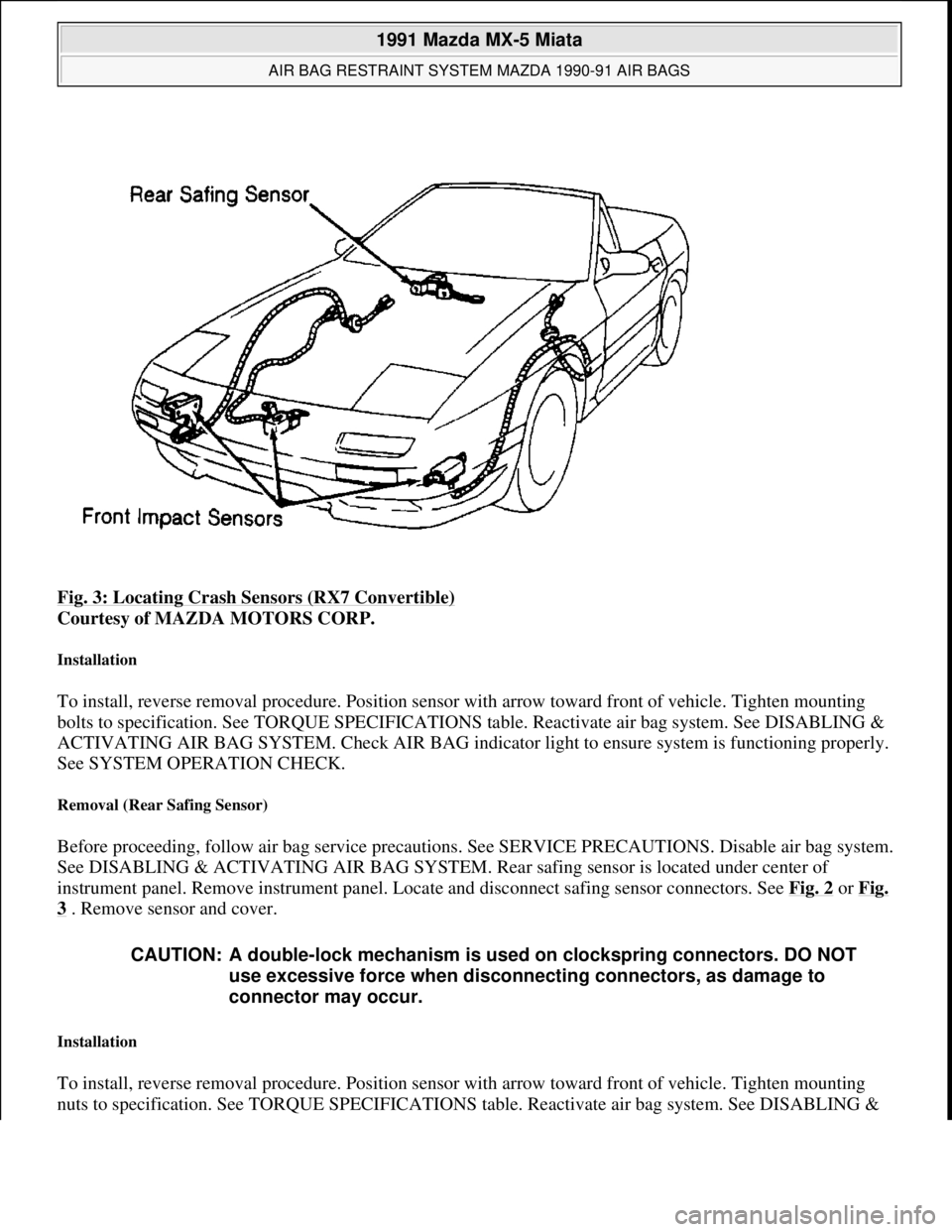
Fig. 3: Locating Crash Sensors (RX7 Convertible)
Courtesy of MAZDA MOTORS CORP.
Installation
To install, reverse removal procedure. Position sensor with arrow toward front of vehicle. Tighten mounting
bolts to specification. See TORQUE SPECIFICATIONS table. Reactivate air bag system. See DISABLING &
ACTIVATING AIR BAG SYSTEM. Check AIR BAG indicator light to ensure system is functioning properly.
See SYSTEM OPERATION CHECK.
Removal (Rear Safing Sensor)
Before proceeding, follow air bag service precautions. See SERVICE PRECAUTIONS. Disable air bag system.
See DISABLING & ACTIVATING AIR BAG SYSTEM. Rear safing sensor is located under center of
instrument panel. Remove instrument panel. Locate and disconnect safing sensor connectors. See Fig. 2
or Fig.
3 . Remove sensor and cover.
Installation
To install, reverse removal procedure. Position sensor with arrow toward front of vehicle. Tighten mounting
nuts to specification. See TORQUE SPECIFICATIONS table. Reactivate air ba
g system. See DISABLING &
CAUTION: A double-lock mechanism is used on clockspring connectors. DO NOT
use excessive force when disconnecting connectors, as damage to
connector may occur.
1991 Mazda MX-5 Miata
AIR BAG RESTRAINT SYSTEM MAZDA 1990-91 AIR BAGS
Microsoft
Sunday, July 05, 2009 2:11:16 PMPage 6 © 2005 Mitchell Repair Information Company, LLC.
Page 134 of 392
Removal
1. Before proceeding, follow air bag service precautions. See SERVICE PRECAUTIONS. Disable air bag
system. See DISABLING & ACTIVATING AIR BAG SYSTEM.
2. Clockspring connector assembly is located under steering wheel, in steering column. See Fig. 4
or Fig. 5.
Remove air bag module. See AIR BAG MODULE. Remove steering wheel nut and remove steering
wheel with steering wheel puller. Remove column covers. Remove screws. Remove clockspring
connector and combination switch as an assembly.
DIAGNOSTIC MODULE & BACK-UP BATTERY
Removal & Installation
1. Before proceeding, follow air bag service precautions. See SERVICE PRECAUTIONS. Disable air bag
system. See DISABLING & ACTIVATING AIR BAG SYSTEM.
2. Diagnostic module and back-up battery is located under left side of instrument panel. See Fig. 4
or Fig.
5 . Disconnect diagnostic module and back-up battery connectors. Remove nuts. Remove diagnostic
module and back-up battery as an assembly. To install, reverse removal procedure. After diagnostic
module and back-up battery are installed, reactivate air bag system. See DISABLING & ACTIVATING
AIR BAG SYSTEM. Check AIR BAG indicator light to ensure system is functioning properly. See
SYSTEM OPERATION CHECK.
SYSTEM OPERATION CHECK
Turn ignition switch to the ON or START position. AIR BAG warning light in instrument cluster should
illuminate for approximately 6 seconds then go out. This indicates that the air bag system is functioning
properly. If any of the following conditions exists, air bag system is malfunctioning and needs repair.
AIR BAG warning light does not illuminate as described.
AIR BAG warning light stays on for more than 6 seconds.
AIR BAG warning light illuminates while driving.
If air bag system components are replaced for any reason, air bag system must be checked for proper function
after repair. Turn ignition on. AIR BAG warning light should illuminate for approximately 6 seconds then go
out. If AIR BAG warning light does not illuminate as described, air bag system is malfunctioning and needs
repair. If warning light functions as described, check horn operation. If horn does not sound, remove air bag
module and check air bag module and horn switch connections. Always follow service precautions and
deactivate air bag system before performing repairs. See DISABLING & ACTIVATING AIR BAG
SYSTEM .
WIRE REPAIR
DO NOT repair air bag system wiring. If air bag harness connectors are faulty, replace faulty wiring harness.
TORQUE SPECIFICATIONS
1991 Mazda MX-5 Miata
AIR BAG RESTRAINT SYSTEM MAZDA 1990-91 AIR BAGS
Microsoft
Sunday, July 05, 2009 2:11:16 PMPage 9 © 2005 Mitchell Repair Information Company, LLC.
Page 153 of 392
ANTI-LOCK BRAKE SYSTEM
1988-91 BRAKES Mazda Anti-Lock Brake System
DESCRIPTION
The Anti-Lock Brake System (ABS) control unit senses reductions in front and rear wheel speed, and modulates
hydraulic pressure to the brakes to prevent wheel lock-up. The ABS consists of a hydraulic unit, 4 wheel speed
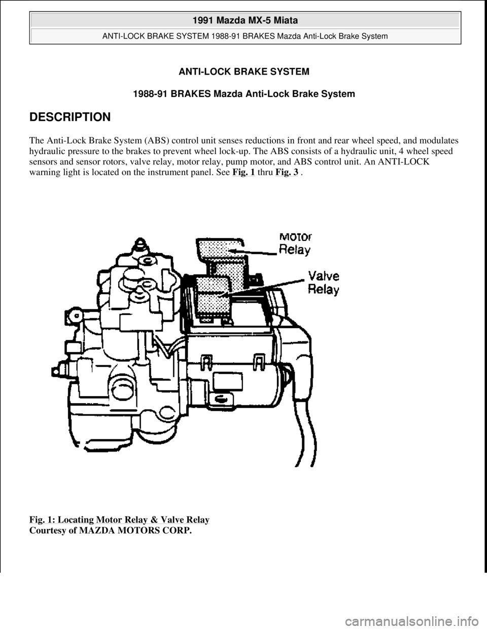
sensors and sensor rotors, valve relay, motor relay, pump motor, and ABS control unit. An ANTI-LOCK
warning light is located on the instrument panel. See Fig. 1
thru Fig. 3 .
Fig. 1: Locating Motor Relay & Valve Relay
Courtesy of MAZDA MOTORS CORP.
1991 Mazda MX-5 Miata
ANTI-LOCK BRAKE SYSTEM 1988-91 BRAKES Mazda Anti-Lock Brake System
1991 Mazda MX-5 Miata
ANTI-LOCK BRAKE SYSTEM 1988-91 BRAKES Mazda Anti-Lock Brake System
Microsoft
Sunday, July 05, 2009 2:17:31 PMPage 1 © 2005 Mitchell Repair Information Company, LLC.
Microsoft
Sunday, July 05, 2009 2:17:36 PMPage 1 © 2005 Mitchell Repair Information Company, LLC.
Page 161 of 392
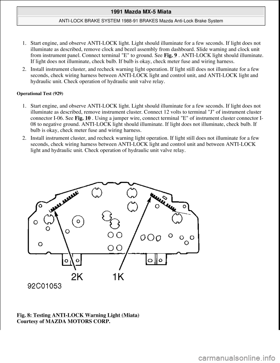
1. Start engine, and observe ANTI-LOCK light. Light should illuminate for a few seconds. If light does not
illuminate as described, remove clock and bezel assembly from dashboard. Slide warning and clock unit
from instrument panel. Connect terminal "E" to ground. See Fig. 9
. ANTI-LOCK light should illuminate.
If light does not illuminate, check bulb. If bulb is okay, check meter fuse and wiring harness.
2. Install instrument cluster, and recheck warning light operation. If light still does not illuminate for a few
seconds, check wiring harness between ANTI-LOCK light and control unit, and ANTI-LOCK light and
hydraulic unit. Check operation of hydraulic unit valve relay.
Operational Test (929)
1. Start engine, and observe ANTI-LOCK light. Light should illuminate for a few seconds. If light does not
illuminate as described, remove instrument cluster. Connect 12 volts to terminal "J" of instrument cluster
connector I-06. See Fig. 10
. Using a jumper wire, connect terminal "E" of instrument cluster connector I-
08 to negative ground. ANTI-LOCK light should illuminate. If light does not illuminate, check bulb. If
bulb is okay, check meter fuse and wiring harness.
2. Install instrument cluster, and recheck warning light operation. If light still does not illuminate for a few
seconds, check wiring harness between ANTI-LOCK light and control unit and between ANTI-LOCK
light and hydraulic unit. Check operation of hydraulic unit valve relay.
Fig. 8: Testing ANTI
-LOCK Warning Light (Miata)
Courtesy of MAZDA MOTORS CORP.
1991 Mazda MX-5 Miata
ANTI-LOCK BRAKE SYSTEM 1988-91 BRAKES Mazda Anti-Lock Brake System
Microsoft
Sunday, July 05, 2009 2:17:31 PMPage 9 © 2005 Mitchell Repair Information Company, LLC.
Page 321 of 392

HEATER SYSTEM
1990-92 Heater Systems
DESCRIPTION & OPERATION
Heater case, mounted under center of instrument panel, contains airflow mode door and air-mix (temperature
blend) door. See Fig. 1
. Blower case, mounted under right end of instrument panel, contains recirculated/fresh
air door. All doors are controlled manually from control panel by cable.
Blower motor relay, in left rear corner of engine compartment (on relay cluster), supplies power to blower
motor. Blower resistors, on bottom of blower case, determine blower speed.
Fig. 1: Exploded View of Heater Case
Courtesy of MAZDA MOTORS CORP. WARNING:To avoid injury from accidental air bag deployment, read and carefully
follow all SERVICE PRECAUTIONS and DISABLING & ACTIVATING AIR
BAG SYSTEM procedures in AIR BAG article in the
ACCESSORIES/SAFETY EQUIPMENT Section.
1991 Mazda MX-5 Miata
HEATER SYSTEM 1990-92 Heater Systems
1991 Mazda MX-5 Miata
HEATER SYSTEM 1990-92 Heater Systems
Microsoft
Sunday, July 05, 2009 2:12:14 PMPage 1 © 2005 Mitchell Repair Information Company, LLC.
Microsoft
Sunday, July 05, 2009 2:12:18 PMPage 1 © 2005 Mitchell Repair Information Company, LLC.
Page 325 of 392
Drain coolant. Disconnect heater hoses at engine compartment firewall. Remove grommets from holes (if
equipped). Remove instrument panel. Remove heater case. Disassemble case and remove heater core. See Fig.
1 . To install, reverse removal procedure. Fill cooling system.
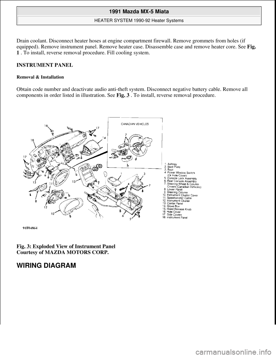
INSTRUMENT PANEL
Removal & Installation
Obtain code number and deactivate audio anti-theft system. Disconnect negative battery cable. Remove all
components in order listed in illustration. See Fig. 3
. To install, reverse removal procedure.
Fig. 3: Exploded View of Instrument Panel
Courtesy of MAZDA MOTORS CORP.
WIRING DIAGRAM
1991 Mazda MX-5 Miata
HEATER SYSTEM 1990-92 Heater Systems
Microsoft
Sunday, July 05, 2009 2:12:14 PMPage 5 © 2005 Mitchell Repair Information Company, LLC.
Page 327 of 392
A/C-HEATER SYSTEM - MANUAL
1990-92 Manual A/C-Heater Systems
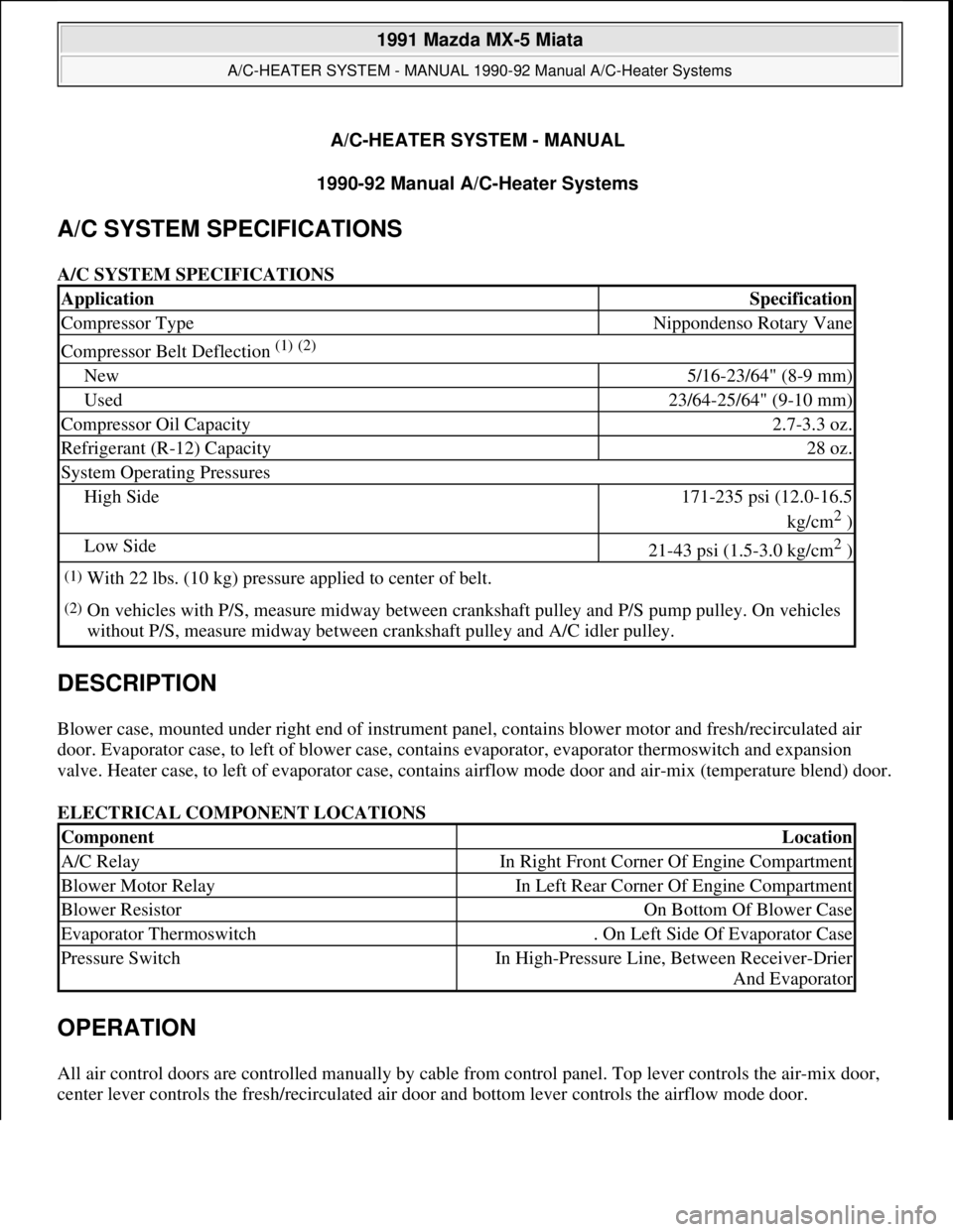
A/C SYSTEM SPECIFICATIONS
A/C SYSTEM SPECIFICATIONS
DESCRIPTION
Blower case, mounted under right end of instrument panel, contains blower motor and fresh/recirculated air
door. Evaporator case, to left of blower case, contains evaporator, evaporator thermoswitch and expansion
valve. Heater case, to left of evaporator case, contains airflow mode door and air-mix (temperature blend) door.
ELECTRICAL COMPONENT LOCATIONS
OPERATION
All air control doors are controlled manually by cable from control panel. Top lever controls the air-mix door,
center lever controls the fresh/recirculated air door and bottom lever controls the airflow mode door.
ApplicationSpecification
Compressor TypeNippondenso Rotary Vane
Compressor Belt Deflection (1) (2)
New5/16-23/64" (8-9 mm)
Used23/64-25/64" (9-10 mm)
Compressor Oil Capacity2.7-3.3 oz.
Refrigerant (R-12) Capacity28 oz.
System Operating Pressures
High Side171-235 psi (12.0-16.5
kg/cm
2 )
Low Side21-43 psi (1.5-3.0 kg/cm2 )
(1)With 22 lbs. (10 kg) pressure applied to center of belt.
(2)On vehicles with P/S, measure midway between crankshaft pulley and P/S pump pulley. On vehicles
without P/S, measure midway between crankshaft pulley and A/C idler pulley.
ComponentLocation
A/C RelayIn Right Front Corner Of Engine Compartment
Blower Motor RelayIn Left Rear Corner Of Engine Compartment
Blower ResistorOn Bottom Of Blower Case
Evaporator Thermoswitch. On Left Side Of Evaporator Case
Pressure SwitchIn High-Pressure Line, Between Receiver-Drier
And Evaporator
1991 Mazda MX-5 Miata
A/C-HEATER SYSTEM - MANUAL 1990-92 Manual A/C-Heater Systems
1991 Mazda MX-5 Miata
A/C-HEATER SYSTEM - MANUAL 1990-92 Manual A/C-Heater Systems
Microsoft
Sunday, July 05, 2009 2:11:52 PMPage 1 © 2005 Mitchell Repair Information Company, LLC.
Microsoft
Sunday, July 05, 2009 2:11:56 PMPage 1 © 2005 Mitchell Repair Information Company, LLC.
Page 334 of 392

Fig. 3: Exploded View of Evaporator Case
Courtesy of MAZDA MOTORS CORP.
HEATER CORE
Removal & Installation
Drain coolant. Disconnect heater hoses at engine compartment firewall. Remove grommets from holes (if
equipped). Remove instrument panel. Remove heater case. Disassemble case and remove heater core. See Fig.
1 . To install, reverse removal procedure. Fill cooling system.
INSTRUMENT PANEL
1991 Mazda MX-5 Miata
A/C-HEATER SYSTEM - MANUAL 1990-92 Manual A/C-Heater Systems
Microsoft
Sunday, July 05, 2009 2:11:52 PMPage 8 © 2005 Mitchell Repair Information Company, LLC.
Page 335 of 392
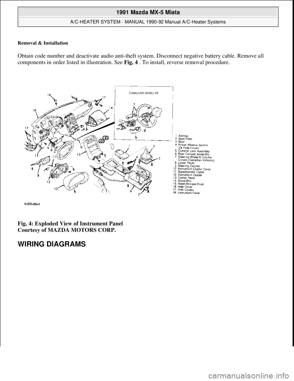
Removal & Installation
Obtain code number and deactivate audio anti-theft system. Disconnect negative battery cable. Remove all
components in order listed in illustration. See Fig. 4
. To install, reverse removal procedure.
Fig. 4: Exploded View of Instrument Panel
Courtesy of MAZDA MOTORS CORP.
WIRING DIAGRAMS
1991 Mazda MX-5 Miata
A/C-HEATER SYSTEM - MANUAL 1990-92 Manual A/C-Heater Systems
Microsoft
Sunday, July 05, 2009 2:11:52 PMPage 9 © 2005 Mitchell Repair Information Company, LLC.