steering wheel adjustment MAZDA MIATA 1991 Factory Service Manual
[x] Cancel search | Manufacturer: MAZDA, Model Year: 1991, Model line: MIATA, Model: MAZDA MIATA 1991Pages: 392, PDF Size: 29.45 MB
Page 129 of 392
ADJUSTMENTS
CLOCKSPRING CENTERING
Set front wheels in straight-ahead position. Turn clockspring connector clockwise until it stops (do not force).
Return connector 2 3/4 turns counterclockwise. Rotate clockspring connector further, if necessary, to align
marks on connector and outer housing.
DISPOSAL PROCEDURES
DEPLOYED AIR BAG
Dispose deployed air bag module as you would any other part. Wear gloves and safety glasses when handling
air bag module.
SCRAPPED VEHICLE
1. Ensure vehicle is outside, and away from other vehicles and people. Open convertible top and doors.
Disconnect negative battery cable.
2. Ensure air bag module is firmly mounted to steering wheel. Remove knee protector and disconnect
Orange and Blue clockspring connectors at base of steering column. See Fig. 1
. Cut clockspring
connector Blue wires.
3. Connect 2 jumper wires (20 feet long) to cut clockspring wires. Connect other ends of wires to a 12-volt
battery to deploy air bag. Because of heat, wait 10 MINUTES before touching deployed air bag.
REMOVAL & INSTALLATION
CRASH SENSORS NOTE: Perform the following procedures when scrapping a vehicle with undeployed air
bag.
WARNING:Follow air bag service precautions to prevent accidentalair bag
deployment and personal injury. See SERVICE PRECAUTIONS.
NOTE: After component replacement, check system to ensure proper operation. See
SYSTEM OPERATION CHECK.
NOTE: Crash sensor orientation and mounting is important for proper operation. All
sensors must be positioned so that arrow points forward. If there is sheet metal
damage near sensor mounting point, inspect body structure at sensor
mounting point for deformation. If damaged, restore to original shape. Ensure
sensor mounting bolts or nuts are tightened to specification. See TORQUE
SPECIFICATIONS table.
1991 Mazda MX-5 Miata
AIR BAG RESTRAINT SYSTEM MAZDA 1990-91 AIR BAGS
Microsoft
Sunday, July 05, 2009 2:11:16 PMPage 4 © 2005 Mitchell Repair Information Company, LLC.
Page 133 of 392
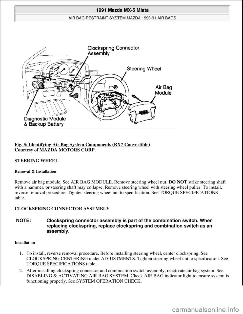
Fig. 5: Identifying Air Bag System Components (RX7 Convertible)
Courtesy of MAZDA MOTORS CORP.
STEERING WHEEL
Removal & Installation
Remove air bag module. See AIR BAG MODULE. Remove steering wheel nut. DO NOT strike steering shaft
with a hammer, or steering shaft may collapse. Remove steering wheel with steering wheel puller. To install,
reverse removal procedure. Tighten steering wheel nut to specification. See TORQUE SPECIFICATIONS
table.
CLOCKSPRING CONNECTOR ASSEMBLY
Installation
1. To install, reverse removal procedure. Before installing steering wheel, center clockspring. See
CLOCKSPRING CENTERING under ADJUSTMENTS. Tighten steering wheel nut to specification. See
TORQUE SPECIFICATIONS table.
2. After installing clockspring connector and combination switch assembly, reactivate air bag system. See
DISABLING & ACTIVATING AIR BAG SYSTEM. Check AIR BAG indicator light to ensure system is
functionin
g properly. See SYSTEM OPERATION CHECK.
NOTE: Clockspring connector assembly is part of the combination switch. When
replacing clockspring, replace clockspring and combination switch as an
assembly.
1991 Mazda MX-5 Miata
AIR BAG RESTRAINT SYSTEM MAZDA 1990-91 AIR BAGS
Microsoft
Sunday, July 05, 2009 2:11:16 PMPage 8 © 2005 Mitchell Repair Information Company, LLC.
Page 299 of 392
SUSPENSION - FRONT
1990-91 SUSPENSION Front
DESCRIPTION
An independent front suspension with MacPherson struts is used on all models except Miata. Miata uses a
double wishbone design with coil over shock absorbers. See Fig. 1
. Strut assemblies mount between steering
knuckle and upper fender panels. Strut assemblies consist of inner shock absorbers and coil springs surrounding
outside of strut tube housing.
The steering knuckle is connected to lower control arm and strut. Lower control arm pivots at crossmember and
is connected by ball joint to steering knuckle. All models are equipped with a stabilizer bar which attaches to
each lower control arm and frame. See Fig. 1
- Fig. 5 . Some models may also be equipped with Auto Adjust
Suspension (AAS). For more information on this system, see ELECTRONIC SUSPENSION article in the
SUSPENSION section.
ADJUSTMENTS & INSPECTION
WHEEL ALIGNMENT SPECIFICATIONS & PROCEDURES
See WHEEL ALIGNMENT SPECIFICATIONS AND PROCEDURES article in the WHEEL ALIGNMENT
section.
WHEEL BEARING
Miata, Protege & 323
Raise and support vehicle. Remove wheel assembly. Remove and wire aside brake caliper. Remove rotor.
Install a dial indicator against wheel hub and measure axial movement. Axial movement should be .002" (.05
mm) maximum. If specification is exceeded, check and adjust lock nut torque or replace bearing on Protege and
323 or hub and bearing assembly on Miata.
MPV & 929
Raise and support vehicle. Remove wheel assembly. Remove and wire aside brake caliper. Install a dial
indicator against wheel hub and measure axial movement. Maximum axial movement should be .002" (.05
mm). If specification is exceeded, check and adjust lock nut torque or replace bearing on MPV 4WD and 929 or
hub and bearing assembly on MPV 2WD.
RX7
1. Raise and support vehicle. Remove wheel assembly. Remove and wire aside brake caliper. Install a dial
indicator against hub and measure axial movement. Axial movement should be zero. If specification is
exceeded, adjust preload or replace wheel bearing.
2. To ad
just preload, remove grease cap, cotter pin and set cover. Loosen lock nut. Tighten to 14-22 ft. lbs.
1991 Mazda MX-5 Miata
SUSPENSION - FRONT 1990-91 SUSPENSION Front
1991 Mazda MX-5 Miata
SUSPENSION - FRONT 1990-91 SUSPENSION Front
Microsoft
Sunday, July 05, 2009 2:08:53 PMPage 1 © 2005 Mitchell Repair Information Company, LLC.
Microsoft
Sunday, July 05, 2009 2:09:01 PMPage 1 © 2005 Mitchell Repair Information Company, LLC.
Page 305 of 392
1. Raise and support vehicle. Remove wheel assembly. Remove axle lock nut. Remove cotter pin, and
disconnect tie rod from steering knuckle. Remove and wire aside brake caliper.
2. Separate lower control arm from ball joint. Remove bolt attaching ball joint to steering knuckle. Remove
bolts retaining steering knuckle to strut assembly. Separate hub and knuckle from drive shaft. Remove
wheel hub and rotor from knuckle. Remove bearings and oil seals.
Removal (MX-6 & 626)
1. Raise and support vehicle. Remove wheel assembly. Disconnect tie rod end from steering knuckle.
Disconnect stabilizer bar from lower control arm. Remove axle lock nut.
2. Disconnect brake line from strut assembly. Remove and wire aside brake caliper. Remove wheel speed
sensor. Remove bolt attaching ball joint to steering knuckle. Remove bolts attaching steering knuckle to
strut assembly. Remove steering knuckle.
3. Remove wheel hub from knuckle using Puller Set (49-G033-1A1). Remove snap ring. Remove wheel
bearing from steering knuckle using Remover (49-G033-106).
Removal (Protege, 323 & 929)
1. Raise and support vehicle. Remove wheel assembly. Remove axle lock nut. Remove cotter pin, and
disconnect tie rod from steering knuckle. Remove and wire aside brake caliper. Separate lower control
arm from ball joint. Remove bolts retaining steering knuckle to strut assembly.
2. On Protege and 323, separate hub and knuckle from drive shaft. Remove wheel hub and rotor from
knuckle. Place alignment marks on rotor and wheel hub. Separate and remove dust cover. Remove
bearings, oil seals, bearing outer races and spacer.
3. On 929, remove hub and rotor. Remove grease seal, sensor ring and circlip. Press bearing from hub
assembly. DO NOT reuse old bearing once pressed from hub.
Removal (RX7)
Raise and support vehicle. Remove wheel assembly. Remove and wire aside brake caliper. Remove grease cap,
cotter pin, nut lock and spindle nut. Remove washer and outer wheel bearing. Remove hub and rotor assembly.
Remove wheel speed sensor ring. Remove inner oil seal and wheel bearing.
Inspection (All Models)
Wash all disassembled parts before inspection. Check for damage, excessive wear and signs of bearing seizure.
Inspect steering knuckle and hub for cracks, scoring and rust. Check for damaged dust cover and poor fit with
steering knuckle.
Installation (All Models)
To install, reverse removal procedure. Adjust wheel bearing preload. See WHEEL BEARING under
ADJUSTMENTS & INSPECTION
. NOTE: If bearings need to be replaced on RX7, also replace hub.
1991 Mazda MX-5 Miata
SUSPENSION - FRONT 1990-91 SUSPENSION Front
Microsoft
Sunday, July 05, 2009 2:08:54 PMPage 7 © 2005 Mitchell Repair Information Company, LLC.
Page 308 of 392

Inspection
Check for damage, oil leakage and abnormal noise. Check rubber parts for deterioration or damage. Inspect coil
spring for signs of fatigue or damage. Replace parts as needed.
Reassembly
Clamp shock absorber in vise. Install coil spring and components in reverse order of disassembly. Ensure coil
spring is well seated in upper and lower spring seats.
Installation
To install, reverse removal procedure. Final tighten all bolts with vehicle resting on ground and suspension
unloaded. See appropriate See SPECIFICATIONS & PROCEDURES article in the WHEEL ALIGNMENT
section for checks and adjustments.
STRUT ASSEMBLY
Removal
1. Raise and support vehicle. Remove wheel assembly. Disconnect brake line from strut assembly. Remove
bolts attaching steering knuckle arm to strut assembly.
2. Disconnect harness connector from actuator (if equipped). Remove bolts, actuator and actuator mounting
bracket from upper mounting block. Remove nuts attaching upper strut assembly to body panel. Remove
strut assembly.
Disassembly
Clamp strut in vise. Compress coil spring using coil spring compressor. Remove piston lock nut. Slowly release
compressor tension. Remove components. Remove coil spring. Remove strut from vise.
Inspection
Check strut tube for cracks, damage, oil leakage and abnormal noise. Check rubber parts for deterioration or
damage. Inspect coil spring for signs of fatigue or damage. Check actuator control rod of strut assembly for
smooth rotation (if equipped). Replace parts as needed.
Reassembly
Clamp strut in vise. Install coil spring and components in reverse order of disassembly. Ensure that coil spring
is well seated in upper and lower spring seats. On MX-6 and 626, ensure upper spring seat positioning hole
faces inside of vehicle. NOTE: Prior to removing strut-to-steering knuckle bolts, make an alignment mark for
reassembly reference. Note position of mounting mark on top of strut assembly
before removing strut.
1991 Mazda MX-5 Miata
SUSPENSION - FRONT 1990-91 SUSPENSION Front
Microsoft
Sunday, July 05, 2009 2:08:54 PMPage 10 © 2005 Mitchell Repair Information Company, LLC.
Page 340 of 392
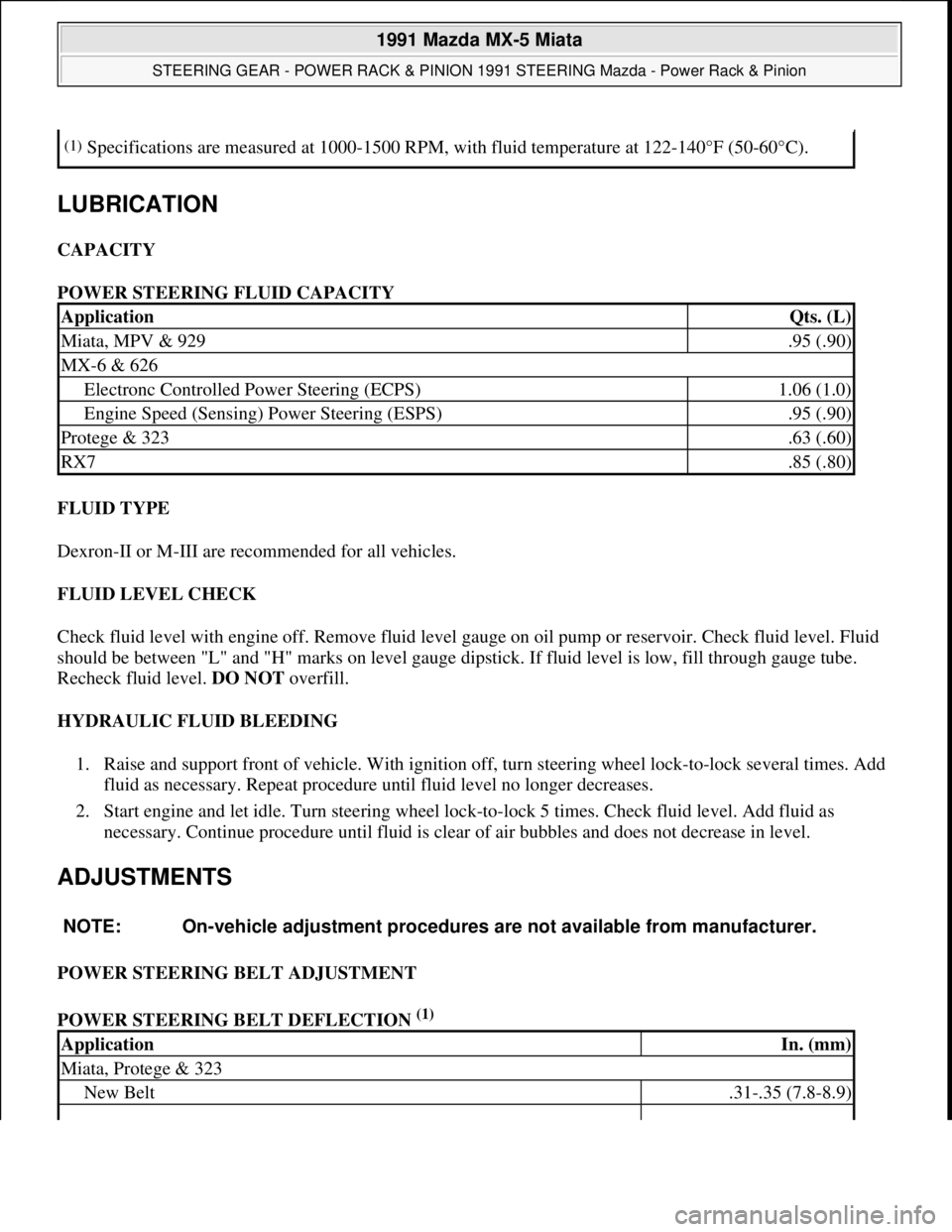
LUBRICATION
CAPACITY
POWER STEERING FLUID CAPACITY
FLUID TYPE
Dexron-II or M-III are recommended for all vehicles.
FLUID LEVEL CHECK
Check fluid level with engine off. Remove fluid level gauge on oil pump or reservoir. Check fluid level. Fluid
should be between "L" and "H" marks on level gauge dipstick. If fluid level is low, fill through gauge tube.
Recheck fluid level. DO NOT overfill.
HYDRAULIC FLUID BLEEDING
1. Raise and support front of vehicle. With ignition off, turn steering wheel lock-to-lock several times. Add
fluid as necessary. Repeat procedure until fluid level no longer decreases.
2. Start engine and let idle. Turn steering wheel lock-to-lock 5 times. Check fluid level. Add fluid as
necessary. Continue procedure until fluid is clear of air bubbles and does not decrease in level.
ADJUSTMENTS
POWER STEERING BELT ADJUSTMENT
POWER STEERING BELT DEFLECTION
(1)
(1)Specifications are measured at 1000-1500 RPM, with fluid temperature at 122-140°F (50-60°C).
ApplicationQts. (L)
Miata, MPV & 929.95 (.90)
MX-6 & 626
Electronc Controlled Power Steering (ECPS)1.06 (1.0)
Engine Speed (Sensing) Power Steering (ESPS).95 (.90)
Protege & 323.63 (.60)
RX7.85 (.80)
NOTE: On-vehicle adjustment procedures are not available from manufacturer.
ApplicationIn. (mm)
Miata, Protege & 323
New Belt.31-.35 (7.8-8.9)
1991 Mazda MX-5 Miata
STEERING GEAR - POWER RACK & PINION 1991 STEERING Mazda - Power Rack & Pinion
Microsoft
Sunday, July 05, 2009 2:10:15 PMPage 3 © 2005 Mitchell Repair Information Company, LLC.
Page 343 of 392

table. Bleed air from system. Check fluid level. Check for leaks. Adjust alignment (if necessary).
POWER STEERING PUMP
Removal & Installation
1. Raise and support front of vehicle. On MX-6 and 626, remove right wheel and splash shield. On all
models remove belt, alternator and hydraulic lines from pump.
2. On Protege and 323, disconnect air cleaner duct and pressure switch. On all models, cap lines to prevent
contamination. Remove bracket-to-pump bolts.
3. To install, reverse removal procedure. Adjust belt tension. See POWER STEERING BELT
DEFLECTION TABLE under ADJUSTMENTS. Bleed air from system. Check for leaks.
OVERHAUL
STEERING GEAR
NOTE: See Fig. 2
-8 for exploded views of rack and pinion steering gears.
1991 Mazda MX-5 Miata
STEERING GEAR - POWER RACK & PINION 1991 STEERING Mazda - Power Rack & Pinion
Microsoft
Sunday, July 05, 2009 2:10:15 PMPage 6 © 2005 Mitchell Repair Information Company, LLC.