tire size MAZDA MIATA 1991 Factory Service Manual
[x] Cancel search | Manufacturer: MAZDA, Model Year: 1991, Model line: MIATA, Model: MAZDA MIATA 1991Pages: 392, PDF Size: 29.45 MB
Page 155 of 392

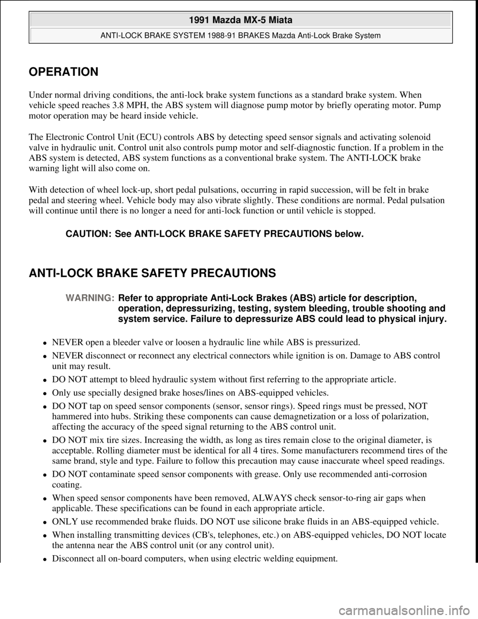
OPERATION
Under normal driving conditions, the anti-lock brake system functions as a standard brake system. When
vehicle speed reaches 3.8 MPH, the ABS system will diagnose pump motor by briefly operating motor. Pump
motor operation may be heard inside vehicle.
The Electronic Control Unit (ECU) controls ABS by detecting speed sensor signals and activating solenoid
valve in hydraulic unit. Control unit also controls pump motor and self-diagnostic function. If a problem in the
ABS system is detected, ABS system functions as a conventional brake system. The ANTI-LOCK brake
warning light will also come on.
With detection of wheel lock-up, short pedal pulsations, occurring in rapid succession, will be felt in brake
pedal and steering wheel. Vehicle body may also vibrate slightly. These conditions are normal. Pedal pulsation
will continue until there is no longer a need for anti-lock function or until vehicle is stopped.
ANTI-LOCK BRAKE SAFETY PRECAUTIONS
NEVER open a bleeder valve or loosen a hydraulic line while ABS is pressurized.
NEVER disconnect or reconnect any electrical connectors while ignition is on. Damage to ABS control
unit may result.
DO NOT attempt to bleed hydraulic system without first referring to the appropriate article.
Only use specially designed brake hoses/lines on ABS-equipped vehicles.
DO NOT tap on speed sensor components (sensor, sensor rings). Speed rings must be pressed, NOT
hammered into hubs. Striking these components can cause demagnetization or a loss of polarization,
affecting the accuracy of the speed signal returning to the ABS control unit.
DO NOT mix tire sizes. Increasing the width, as long as tires remain close to the original diameter, is
acceptable. Rolling diameter must be identical for all 4 tires. Some manufacturers recommend tires of the
same brand, style and type. Failure to follow this precaution may cause inaccurate wheel speed readings.
DO NOT contaminate speed sensor components with grease. Only use recommended anti-corrosion
coating.
When speed sensor components have been removed, ALWAYS check sensor-to-ring air gaps when
applicable. These specifications can be found in each appropriate article.
ONLY use recommended brake fluids. DO NOT use silicone brake fluids in an ABS-equipped vehicle.
When installing transmitting devices (CB's, telephones, etc.) on ABS-equipped vehicles, DO NOT locate
the antenna near the ABS control unit (or any control unit).
Disconnect all on-board computers, when using electric welding equipment. CAUTION: See ANTI-LOCK BRAKE SAFETY PRECAUTIONS below.
WARNING:Refer to appropriate Anti-Lock Brakes (ABS) article for description,
operation, depressurizing, testing, system bleeding, trouble shooting and
system service. Failure to depressurize ABS could lead to physical injury.
1991 Mazda MX-5 Miata
ANTI-LOCK BRAKE SYSTEM 1988-91 BRAKES Mazda Anti-Lock Brake System
Microsoft
Sunday, July 05, 2009 2:17:31 PMPage 3 © 2005 Mitchell Repair Information Company, LLC.
Page 261 of 392

3. Using Bearing Nut Wrench (49 0603 635A ) and Shaft Holder (49 S120 645A ), remove bearing lock nut
from axle shaft. Remove bearing and bearing retainer from axle using Puller (49 S120 520A ). Remove
outer race from hub.
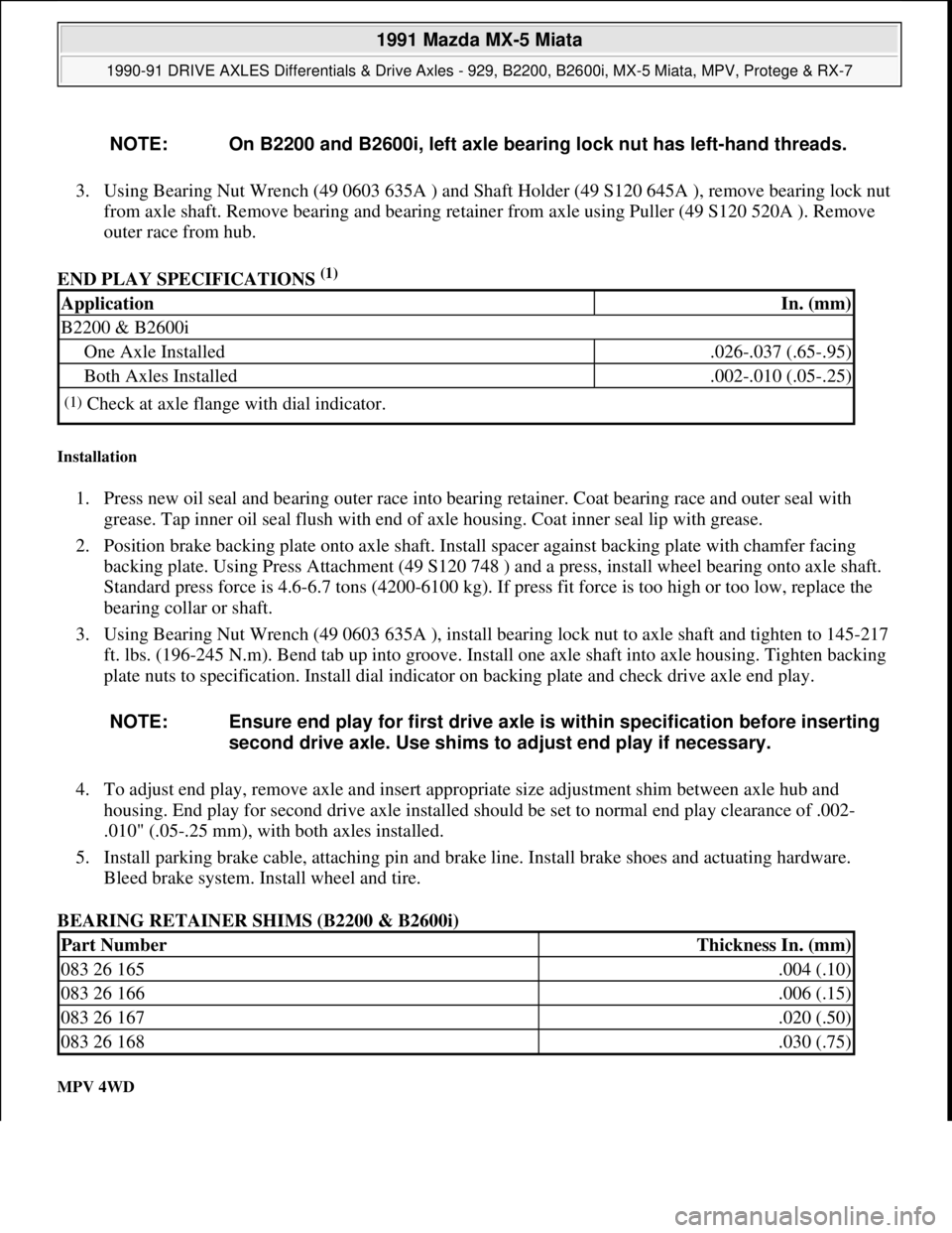
END PLAY SPECIFICATIONS
(1)
Installation
1. Press new oil seal and bearing outer race into bearing retainer. Coat bearing race and outer seal with
grease. Tap inner oil seal flush with end of axle housing. Coat inner seal lip with grease.
2. Position brake backing plate onto axle shaft. Install spacer against backing plate with chamfer facing
backing plate. Using Press Attachment (49 S120 748 ) and a press, install wheel bearing onto axle shaft.
Standard press force is 4.6-6.7 tons (4200-6100 kg). If press fit force is too high or too low, replace the
bearing collar or shaft.
3. Using Bearing Nut Wrench (49 0603 635A ), install bearing lock nut to axle shaft and tighten to 145-217
ft. lbs. (196-245 N.m). Bend tab up into groove. Install one axle shaft into axle housing. Tighten backing
plate nuts to specification. Install dial indicator on backing plate and check drive axle end play.
4. To adjust end play, remove axle and insert appropriate size adjustment shim between axle hub and
housing. End play for second drive axle installed should be set to normal end play clearance of .002-
.010" (.05-.25 mm), with both axles installed.
5. Install parking brake cable, attaching pin and brake line. Install brake shoes and actuating hardware.
Bleed brake system. Install wheel and tire.
BEARING RETAINER SHIMS (B2200 & B2600i)
MPV 4WD
NOTE: On B2200 and B2600i, left axle bearing lock nut has left-hand threads.
ApplicationIn. (mm)
B2200 & B2600i
One Axle Installed.026-.037 (.65-.95)
Both Axles Installed.002-.010 (.05-.25)
(1)Check at axle flange with dial indicator.
NOTE: Ensure end play for first drive axle is within specification before inserting
second drive axle. Use shims to adjust end play if necessary.
Part NumberThickness In. (mm)
083 26 165.004 (.10)
083 26 166.006 (.15)
083 26 167.020 (.50)
083 26 168.030 (.75)
1991 Mazda MX-5 Miata
1990-91 DRIVE AXLES Differentials & Drive Axles - 929, B2200, B2600i, MX-5 Miata, MPV, Protege & RX-7
Microsoft
Sunday, July 05, 2009 2:17:01 PMPage 3 © 2005 Mitchell Repair Information Company, LLC.
Page 319 of 392

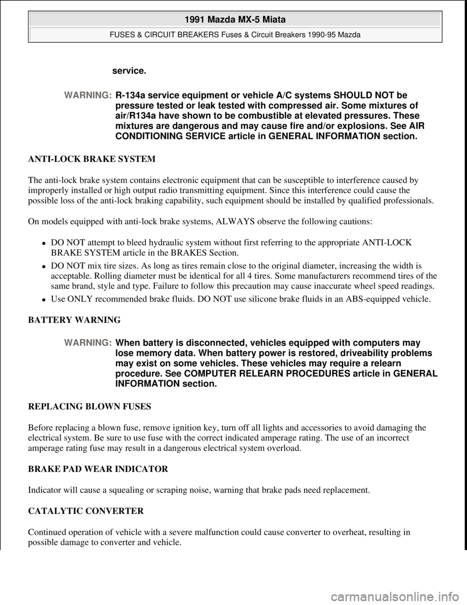
ANTI-LOCK BRAKE SYSTEM
The anti-lock brake system contains electronic equipment that can be susceptible to interference caused by
improperly installed or high output radio transmitting equipment. Since this interference could cause the
possible loss of the anti-lock braking capability, such equipment should be installed by qualified professionals.
On models equipped with anti-lock brake systems, ALWAYS observe the following cautions:
DO NOT attempt to bleed hydraulic system without first referring to the appropriate ANTI-LOCK
BRAKE SYSTEM article in the BRAKES Section.
DO NOT mix tire sizes. As long as tires remain close to the original diameter, increasing the width is
acceptable. Rolling diameter must be identical for all 4 tires. Some manufacturers recommend tires of the
same brand, style and type. Failure to follow this precaution may cause inaccurate wheel speed readings.
Use ONLY recommended brake fluids. DO NOT use silicone brake fluids in an ABS-equipped vehicle.
BATTERY WARNING
REPLACING BLOWN FUSES
Before replacing a blown fuse, remove ignition key, turn off all lights and accessories to avoid damaging the
electrical system. Be sure to use fuse with the correct indicated amperage rating. The use of an incorrect
amperage rating fuse may result in a dangerous electrical system overload.
BRAKE PAD WEAR INDICATOR
Indicator will cause a squealing or scraping noise, warning that brake pads need replacement.
CATALYTIC CONVERTER
Continued operation of vehicle with a severe malfunction could cause converter to overheat, resulting in
possible damage to converter and vehicle. service.
WARNING:R-134a service equipment or vehicle A/C systems SHOULD NOT be
pressure tested or leak tested with compressed air. Some mixtures of
air/R134a have shown to be combustible at elevated pressures. These
mixtures are dangerous and may cause fire and/or explosions. See AIR
CONDITIONING SERVICE article in GENERAL INFORMATION section.
WARNING:When battery is disconnected, vehicles equipped with computers may
lose memory data. When battery power is restored, driveability problems
may exist on some vehicles. These vehicles may require a relearn
procedure. See COMPUTER RELEARN PROCEDURES article in GENERAL
INFORMATION section.
1991 Mazda MX-5 Miata
FUSES & CIRCUIT BREAKERS Fuses & Circuit Breakers 1990-95 Mazda
Microsoft
Sunday, July 05, 2009 2:15:54 PMPage 6 © 2005 Mitchell Repair Information Company, LLC.